2-D Meshing of the bracket and creating 1D elements
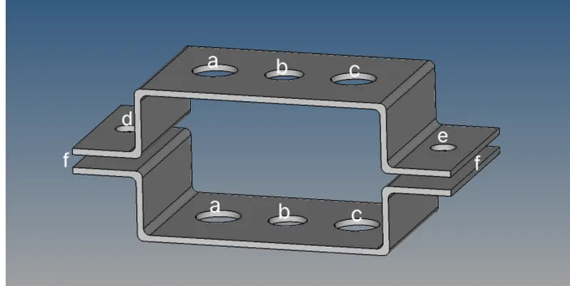
Objective: Mesh the given component and create 1D elements on the following component
Given: 1) Mesh element size: 5mm
2) Magnitude of mass: 10
3) Cross-section and DOF of elements:
a. Rod element:- Translational DOF should be Constrained with RBE2 link
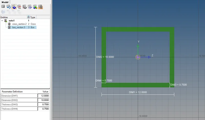
Cross-Section: BOX- Dimension a= 12 mm
dimension b=10 mm
Thickness t= 0.75 mm
b. Beam element:- All DOF should be constrained with RBE3 link
Cross-Section: I Section- Dimension a= 8 mm
Dimension b= 10 mm
Dimension c= 8.5 mm
Thickness t1= 0.75 mm
Thickness t2= .6 mm
Thickness t3= .6 mm
c. Bar element:- Constrain only x and y DOFs With RBE3 link
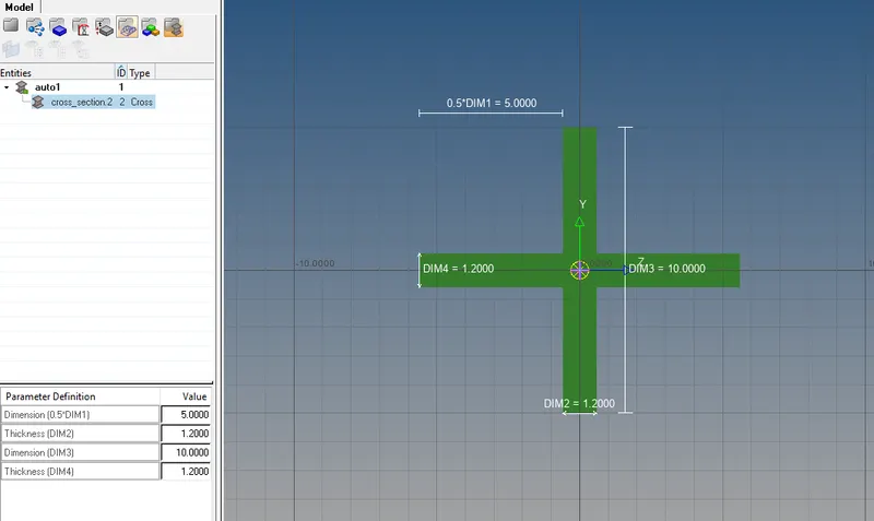
Cross-section: X section- Dimension DIM1= 5 mm
Thickness DIM2= 1.2 mm
Dimension DIM3= 10 mm
Thickness DIM4= 1.2mm
d. & e. Apply the mass of magnitude 10 with RBE2 link
f. Join the two components with Spring elements
Procedure:
1) Import iges file of the model by using the 'import geometry' option and select the iges file to import it.
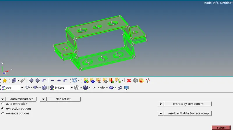
2)Now create a midsurface , so that the entire 3D geometry can be represented as a surface which will reduce the computational time and storage for carrying out the task. For incorporating this, select the 'midsurface' option and select the upper bracket surface for the midsurface creation. Now select 'extraction option' and then select 'skin offset' which ensures a proper midplane generation with all the fillets and curves. Now click the auto extraction option and select create for the same.
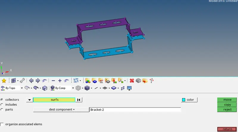
3)Now rename this mid-surface as bracket-1 and then follow the same procedure for the second bracket and create the midsurface and rename it as bracket-2 or you can use the 'organize' command from 'tool' to create a news surface and assign it to the bracket-2.
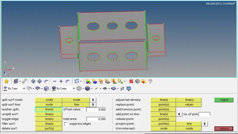
4)Now before creating mesh make sure to washer splits are created for ensuring proper meshing. For that got to 'quickedits' in 'geometry' and select 'washersplit' and give the offset value as 5 after selecting the circle lines.
5) Now to create a mesh, click '2d' option and select the 'automesh' option. Select all the surfaces and set the 'element size' as 5 mm which is the target element size and select the 'mesh types' of quads. The reason behind choosing quads mesh type is that they gave better accurate results and the quad elements can capture stress results better than triangular elements and as the region near the circle has the highest stress concentration it is better to use quad elements.
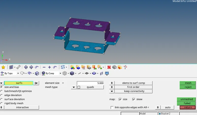
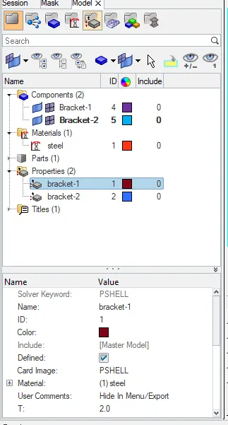
6)After this create material and properties that are required for the creation of 1-d elements.
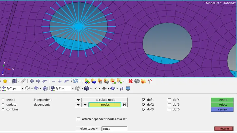
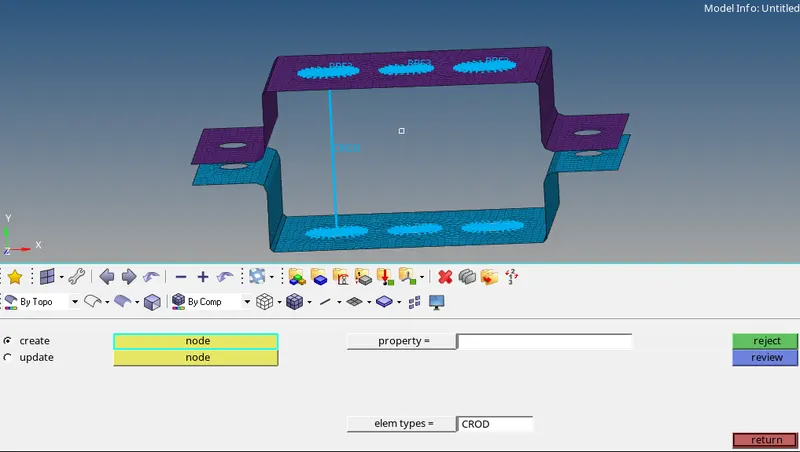
7) For creating rod elements in position 'a' create rbe2 elements surrounding the holes.rbe2 elements have infinite stiffness and it distributes the load uniformly to all the nodes. To create rbe2 select the 'rigid' command from the '1d' tool and select ' calculate node' and 'node by path' for selecting the nodes around the hole which forms the rbe2 links. Uncheck the dof4,5 and 6 so that only transitional motion is constarined.
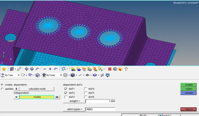
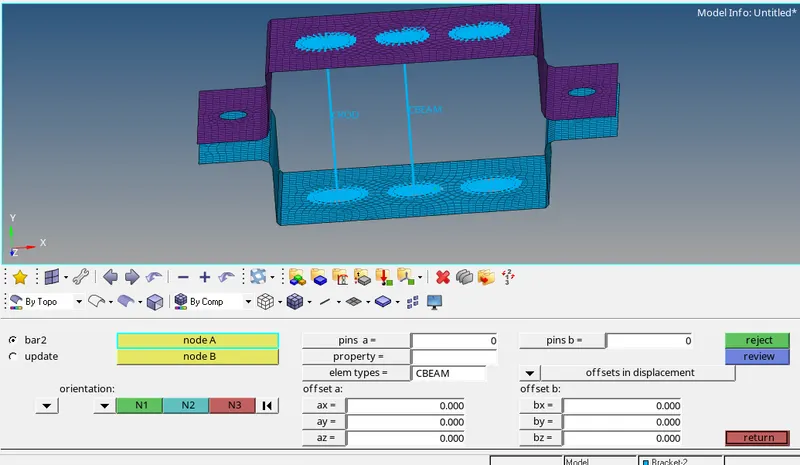
8)For creating beam elements in position 'b' create rbe3 elements surrounding the holes.Rbe3 elements distribute load non-uniformly and the distribution is based upon the proximity of the node from the point of load application(main node).To create rbe3 select the 'rigid' command from the '1d' tool and select ' calculate node' and 'node by path' for selecting the nodes around the hole which forms the rbe2 links. check all the dof to constraiant all kinds of motions.
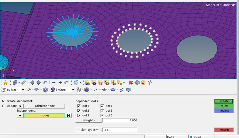
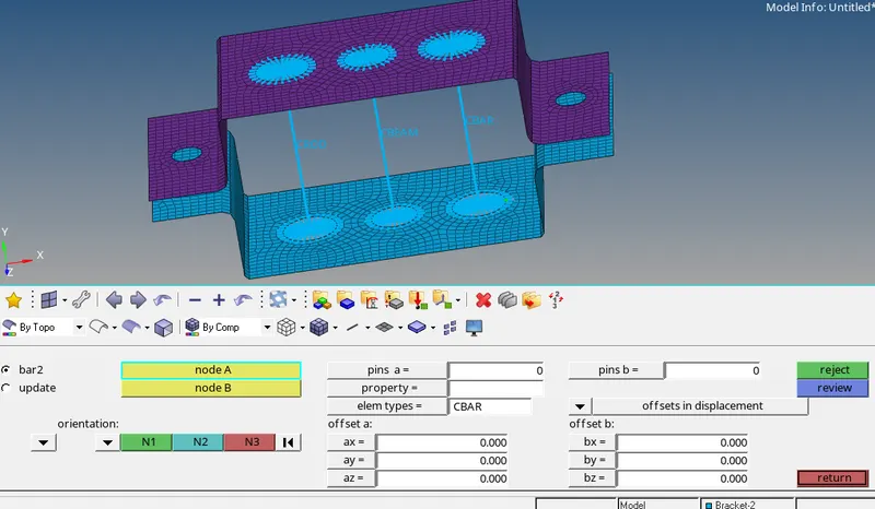
9)For creating bar elements in position 'c' create rbe3 elements surrounding the holes. To create rbe3 select the 'rigid' command from the '1d' tool and select ' calculate node' and 'node by path' for selecting the nodes around the hole which forms the rbe2 links. uncheck all the 4 dof except dof 1 and dof 2 to constraint only x and y directional motions.
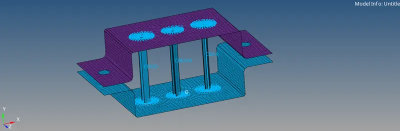
10) Now to create the cross-sections of rod,beam and bar click on 'hyperbeam' -> 'standard section' -> 'Opistruct(for cross and box)/hyperbeam(for I section)'->'create'. Now a hyperbeam window will open where we can edit our cross-section according to the required dimensions.
| BOX CROSS-SECTION(ROD) | I CROSS-SECTION(BEAM) | X CROSS-SECTION(BAR) |
 |
 |
 |
11) Now create the required properties for these rod, beam, and bar and associate with their respective cross-section.
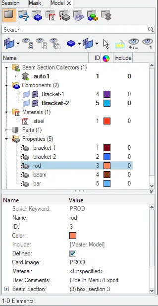
12) For creating rod elements in position 'a' select the 'rod' command from the '1d' tool and select the two rbe2 center nodes of the upper and bottom bracket to create the rod element. select the property as 'rod' and element type as 'crod'.
13)For creating beam elements in position 'a' select the 'bar' command from the '1d' tool and select the two rbe3 center nodes of the upper and bottom bracket to create the beam element. select the property as 'beam', element type as 'cbeam', and give appropriate orientation.
14) For creating bar elements in position 'a' select the 'bar' command from the '1d' tool and select the two rbe3 center nodes of the upper and bottom bracket to create the bar element. select the property as 'bar', element type as 'cbar', and give appropriate orientation.
15) Now to display the cross-section in the window, select ' 1D detailed element representation '.
16) To apply mass at 'd' and 'e' position create rbe2 links and then click on the 'masses' command from the '1d' tool. Then select rebe2 center node for mass application and specify the magnitude of mass as 10,'property' as bracket-1, and 'element type' as cmass1.
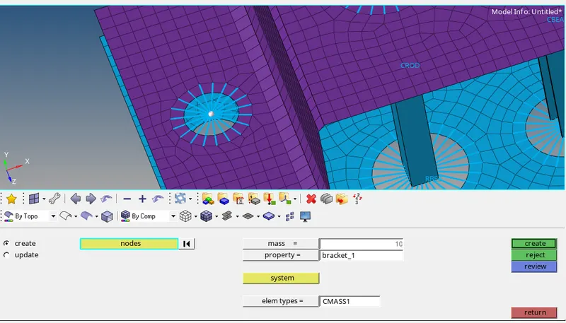
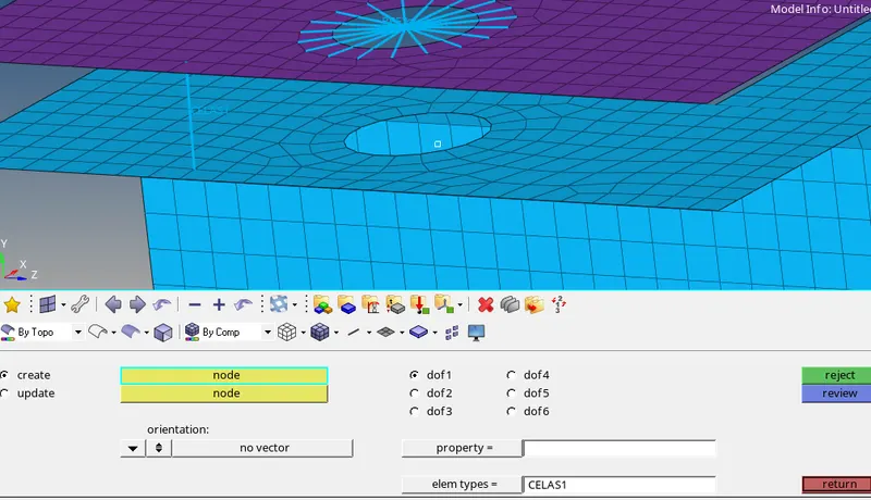
17) To create spring elements between the upper and lower bracket, click on the 'springs' command from the '1d' tool. select two nodes each from the upper and lower bracket and mention 'element type' as celas1.
Results & Final model :
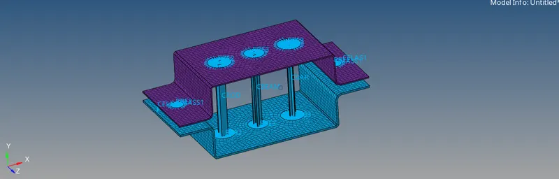
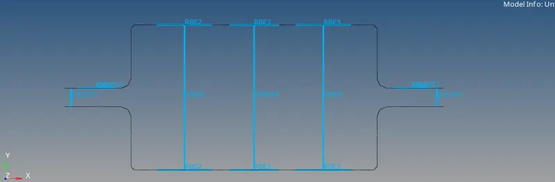
Hence, the midsurface has been created and meshed for the given model. Simultaneously, 1D elements(rod, beam, bar) have been deployed and the cross-section and the property of these elements have been assigned.
ISOMETRIC VIEW:-
SIDE VIEW OF THE ALL THE ELEMENTS:-
The link of the hypermesh model files for the above-mentioned tasks is given below:
https://drive.google.com/drive/folders/1Hz6kksbpjv-D6oom2uEYiyQh3xwvtw8G?usp=sharing