Week 6-Meshing of Hood Challenge
Aim: To generate the mid surface and also to mesh the given hood model.
Quality criteria to be followed is mentioned below, with element size of 5units.
| S.N | Quality Criteria | Value |
| 1 | Aspect Ratio | 5 |
| 2 | Skewness | 45 |
| 3 | Warping | 15 |
| 4 | Taper | 0.5 |
| 5 | Min. Length | 2 Units |
| 6 | Max. Length | 8 Units |
| 7 | Min angle Quad | 45 |
| 8 | Max angle Quad | 135 |
| 9 | Min angle Tria | 20 |
| 10 | Max angle Tria | 120 |
| 10 | Tria % | 10 |
Procedure:
1) Creating Mid surface:
- There are 4 components in the model, namely "inner_extract, outer_extract, hinge_reinforcement_extract 1, & Latch_reinforcement_extract1". We will have to generate the mid surface for each component separately.
- From the Geom tab, select midsurface>auto mid surface and then select extraction options(as skin offset or offset+planes+sweeps) as required according to the option that results in better midsurface.
- The hinge_reinforcement_extract1 has 2 separate solids/bodies in it, so we will make 2 midsurfaces, which makes the number of midsurfaces as 5 for the model, namely, "Hinge-1_mid, Hinge-2_mid, Latch_mid, Outer_Middle Surface, & Inner_Middle Surface".
- Outer_Middle Surface & Inner_Middle Surface are symmetric, so after creating the midsurfaces, we can delete one half from both of them and then use the remaining half for meshing.
- Autocleanup and repair the midsurfaces wherever necessary; assign property and material to all the midsurfaces. Create a "property" with card image: PSHELL and thickness, T: 2.5(as desired). Now create "material" as Steel with Card Image: MAT1. Click on the midsurface(s) to assign property and material to them.
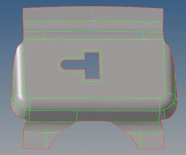
Latch Midsurface
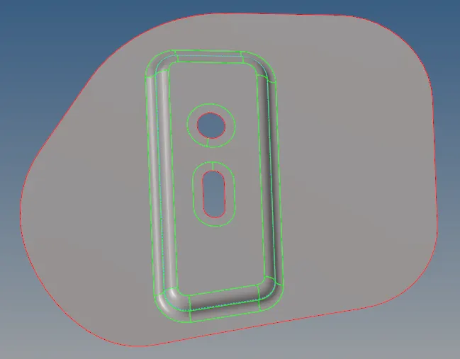
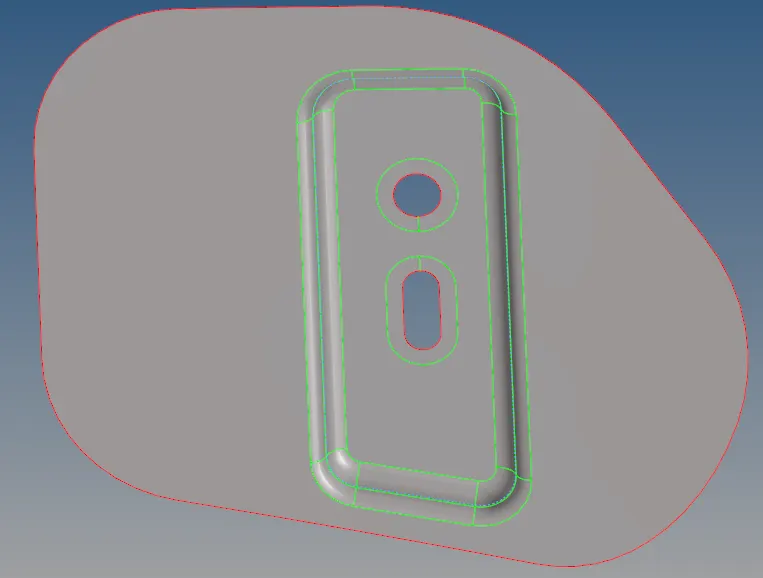
Hinge-1 Midsurface Hinge-2 Midsurface
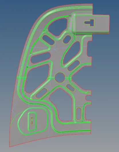
Inner_Middle surface(one half is deleted after creating midsurface since the geometry is symmetric)
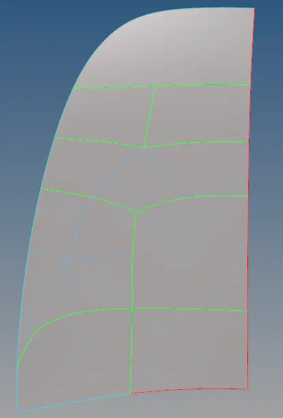
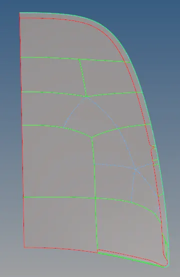
Outer_Middle surface(front view) Outer_Middle surface(backside view)
(one half is deleted after creating midsurface since the geometry is symmetric)
2) Generating the mesh:
- First, enter the Quality criteria. Preferences>Criteria File Settings. Give target element size as 5. Now goto the automesh option in 2D panel. Select Surfs from the dropdown, then element type as mixed with element size:5. Select the surfaces of the midsurface and click on mesh.
- You can use repair the mesh using various options, like
- Automesh: Change type to elems from the dropdown box, select the required area and try toggling until a satisfactory mesh is obtained.
- edit element: 2D>edit element. Use split, create, combine wherever necessary.
- Rebuild mesh: Select elems that you want to rebuild, make sure the element size is assigned the same throughout the process to get the desired output(i.e 5 in our case).
- After meshing the midsurface, the next step is to check the "qualityindex"(2D>qualityindex). First, change the bar to "worse". You will see RED coloured elements which come under the worse category. We have to repair/optimize those elements. Use required "cleanup tools" to meet the purpose of removing worse elements. Now, move the bar to "fail" and repeat this step until Yellow coloured elements which come under the "fail" category disappears.
- While meshing the Outer_Middle Surface, be careful with the Hemming region since that could cause minimum distance length error. To overcome this problem, you can toggle the lines such that we only have only 1 shared edge(Green line) that acts as the midline and then suppress other edges throughout the Hemming region.
- After meshing the inner_Middle Surface and Outer_Middle Surface, we will have to reflect the mesh. Tools>reflect>select the elements that you intend to reflect>Give the axis and base node>reflect.
- There are high chances of having free edges throughout the mesh. You can do this using Tools>edges. Selec the elements for which you want to check the connectivity, then click on "find edges" to findout the free edges in the mesh, increase the search tolerance value(but do not exceed minimum element value), select "preview equiv" so that the nodes that are in search tolerance will be highlighted, then click "equivalence" to connect those highlighted nodes that represent unconnected free edges.
- At times you may come across a condition where nodes are not highlighted. In such a case use the "replace" option from the 2D panel. Tick "equivalence". Also, tick the "at mid-point" box as this will help in selecting the node anywhere on the edge.
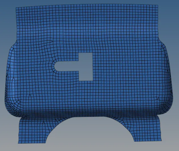
Latch_Mesh
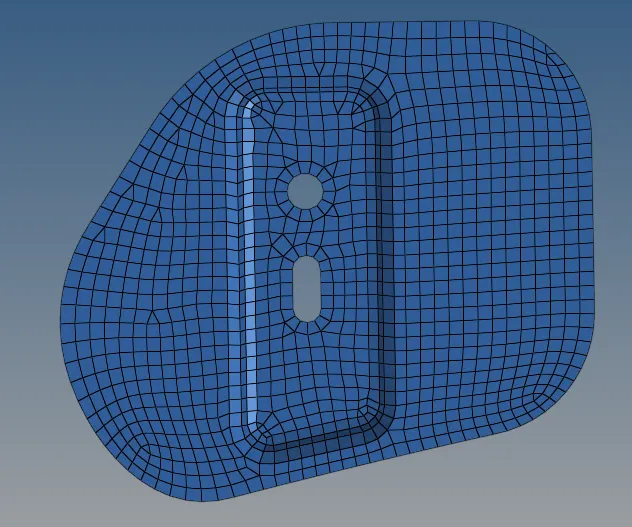
Hinge-1_MESH
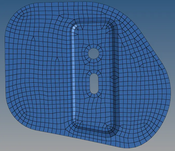
Hinge-2_MESH
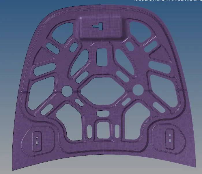
Inner_MESH
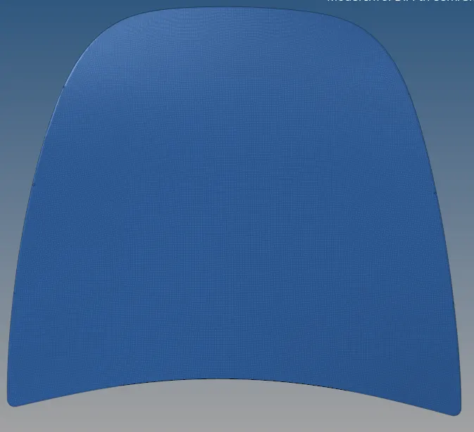
Outer_MESH_frontview
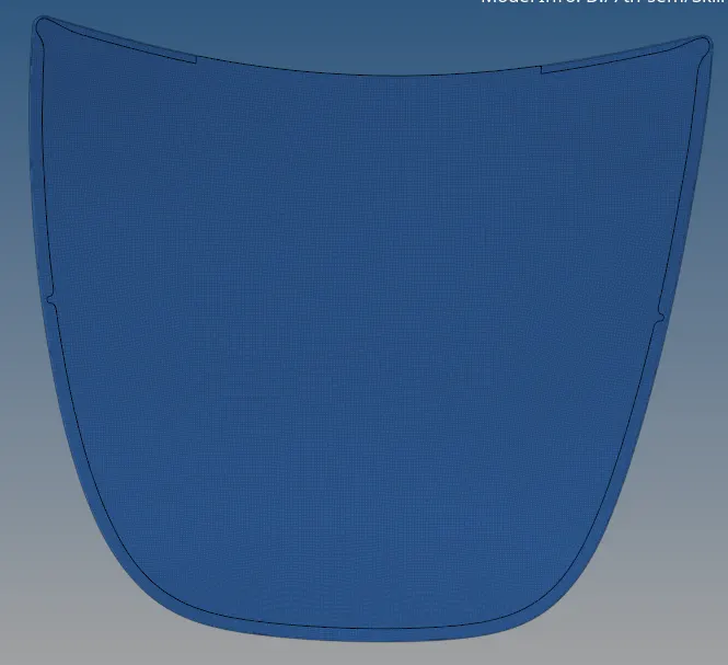
Outer_MESH_backsideview
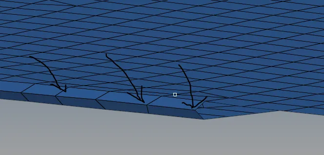
Outer_MESH_HEMMING-REGION throughout the cross-section
3) Model checkup:
- Check for free edges: using the procedure stated above.
- Element to surface: Mesh>Check>Elements>Comparison>Elements(select displayed)>Surfaces(select displayed)>Tolerance:0.2>Run. This will show the entire capture of the geometry. "Red" coloured are ones have to be repaired using "project" option.
Tools>Project>elems>select elements that you want to project>select surfs in and around the selected elements> give axis only on the feature line>project. - Check Normals: Tools>normals. Use either colour display or Vector display. In a colour display, all the elements on one face have to be of one colour and the elements on the other face have to be of the other colour. In vector display, all the elements have to be in the normal direction.
Errors pertaining to the check normals can be rectified like this, Tools>normals>elements>elems>select elems that have to be corrected>display>reverse. - Check duplicates: Geam>defeature>duplicates will show the number of duplicate elements.