Week 4-1D Element Creation Challenge
Procedure:
1. Import the given model as “Import Geometry” and specify the file type as IGES.
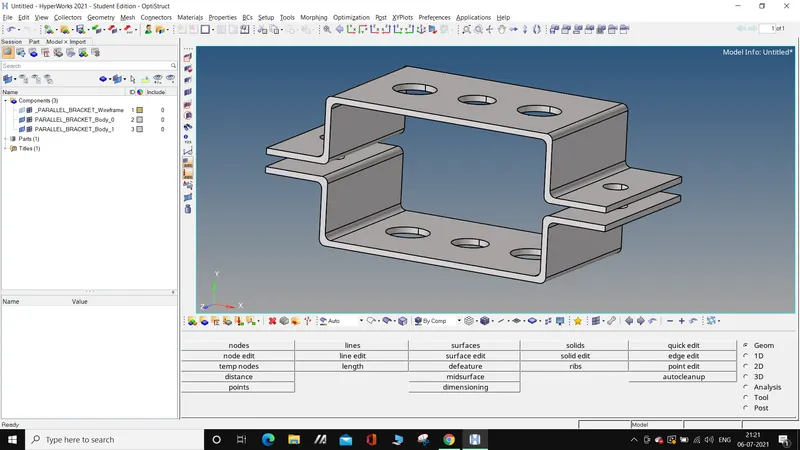
2. Now create 2 mid-surfaces for both the components and name the mid-surfaces as bracket-1 and bracket-2 respectively.
Before that, check out the “extraction options” and choose the “Skin offset” option to get a mid-surface that could be meshed better when we perform 2d meshing on the midsurface.
We know that mid-surface is a 2D representation of 3D components. So, for a 2D component we need thickness. Create a “material” and name it as steel with MAT1 as the “Card Image”.
Now create 2 properties and name them as pbracket-1 and pbracket-2 respectively. In these properties, give PSHELL as “Card image” ; steel as “material”; thickness as 2 and 2.5 for former and latter properties.
Under the component selector, give “property” to bracket-1 and bracket-2. (left click on bracket-1/2>property=pbracket-1/2>material will be auto assigned since we assigned material to pbracket-1/2 earlier).
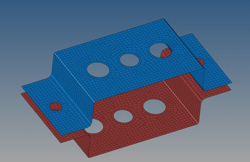
Then, create a 2D mesh on the mid-surface with element size 5 units. Use a “washer split” with an offset value of 4 around all the circles.
Hide the surfaces of the bracket to get a better view of the mesh.
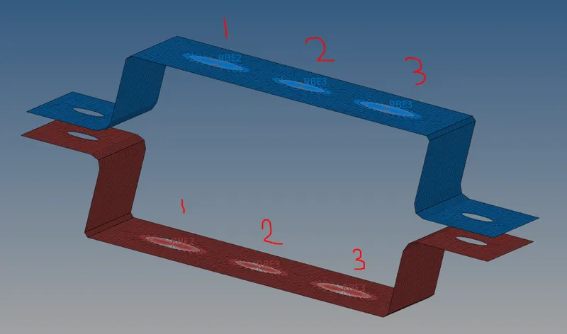
3. Translational DOF should be Constrained with RBE2 link(marked as 1)
1D>rigids>independent:calculate node>dependent:nodes>deselect dof4,dof5 and dof6.
All DOF should be constrained with RBE3 link(marked as 2)
1D>rbe3>keep all dof ticked
Constrain only x and y DOFs With RBE3 link(marked as 3)
1D>rbe3>deselect dof3 and dof6
Note: Make sure to switch between components when working with each of the components, viz. ,when you make a rigid link of bracket-1, keep bracket-1 as current component and while creating rigid link on bracket-2, assign bracket-2 as current component. (rt, click on component>make as current).
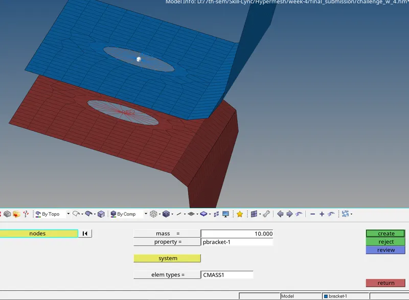
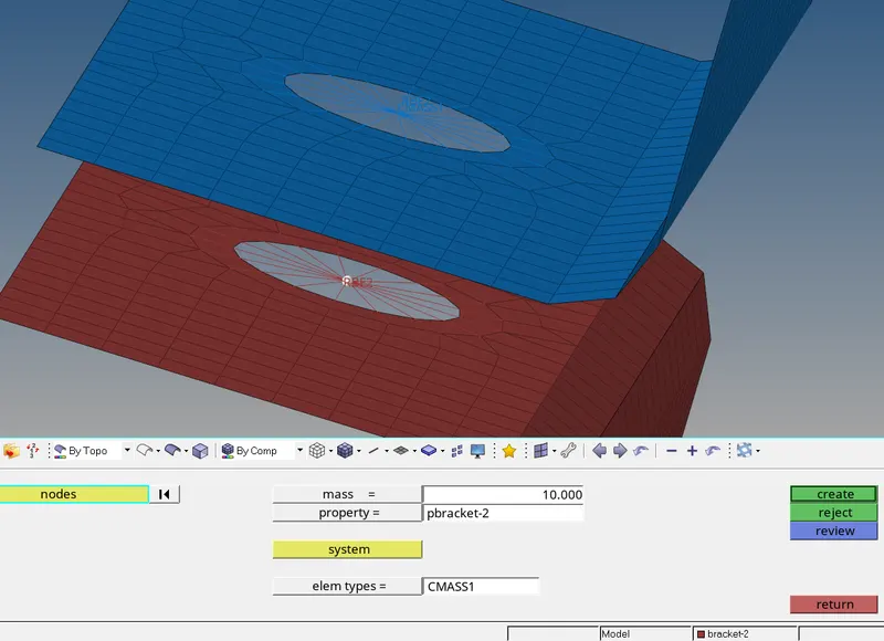
4. Apply the mass of magnitude 10 with the RBE2 link on the remaining holes.
Create rigid links first. Then assign masses.
1D>masses>elem types=CMASS1>mass=10>property=pbracket-1(or 2).
5. Use the “hyperbeam” option now.
1D>hyperbeam>standard section>Thin walled BOX>create required cross-sections of beams i.e BOX in this case. Name it as “box_rod”
Now, the HyperBeam tab opens. Right click>create>standard section>Hypermesh>Standard I section. Name it as “I_beam”
Then, again Right click>create>standard section>Optistruct>Cross. This creates X section. Name it as “X_bar”
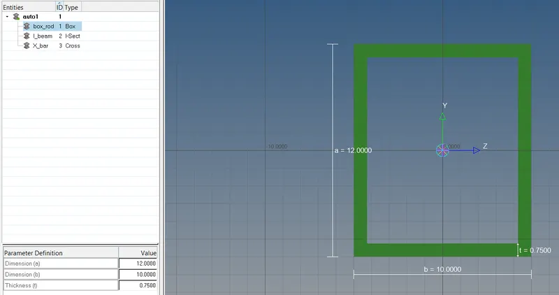
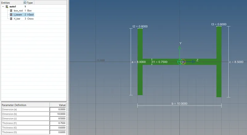
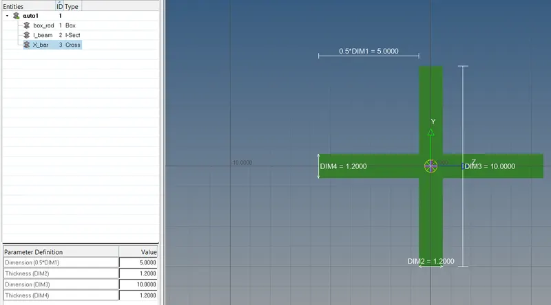
6. Now create properties for these rod, beam and bar elements. Name them as p_box_rod(with card image:PROD, Beam section:box_rod) ;
p_I_beam(with card image:PBEAM, Beam section:I_beam) ;
p_X_bar(with card image:PBAR, Beam section: X_bar).
Then, insert the rod element.
1D>rods>property:p_rod_box>elem types:CROD>choose nodes.
I will use bracket-2 as the “current” model.
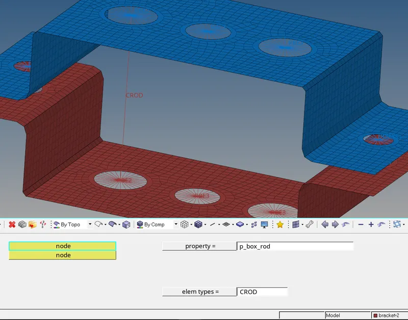
For I_section beam⇒ 1D>bars>elem types:CBEAM>property:p_I_beam>select 2 nodes>choose orientation(N1,N2,N3)
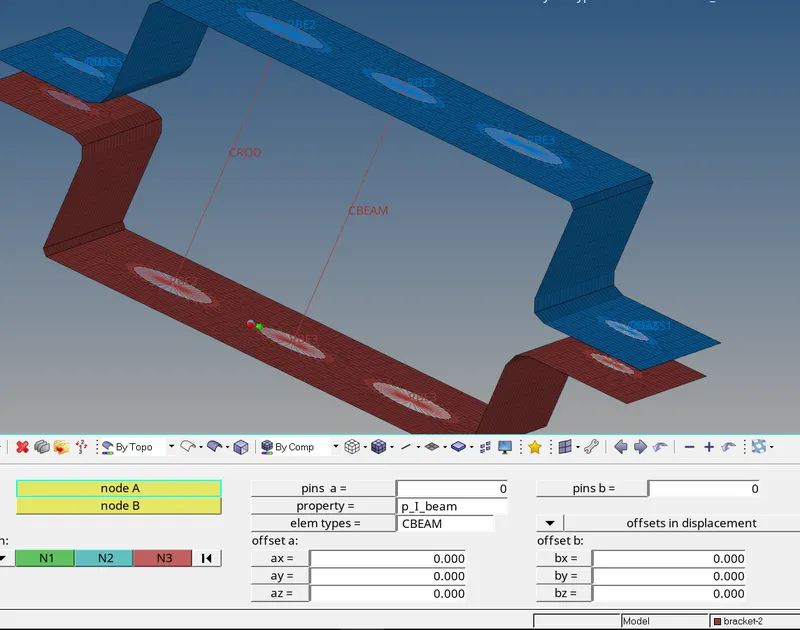
For X-section bar element⇒ 1D>bar>property:p_x_bar>elem types:CBAR>orientation(N1,N2,N3) will be used from the previous case.
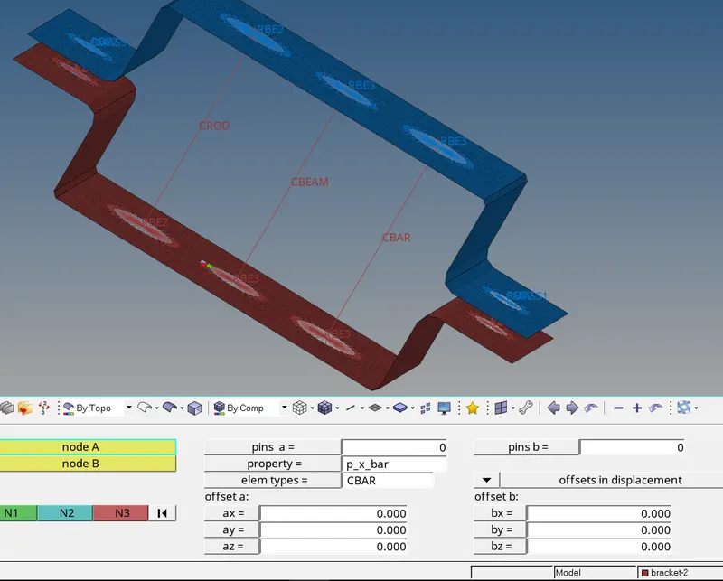
To view 3D view of bar, beam and rod⇒ toggle on the option 1D Traditional Element Representation>1D Detailed Element Representation.
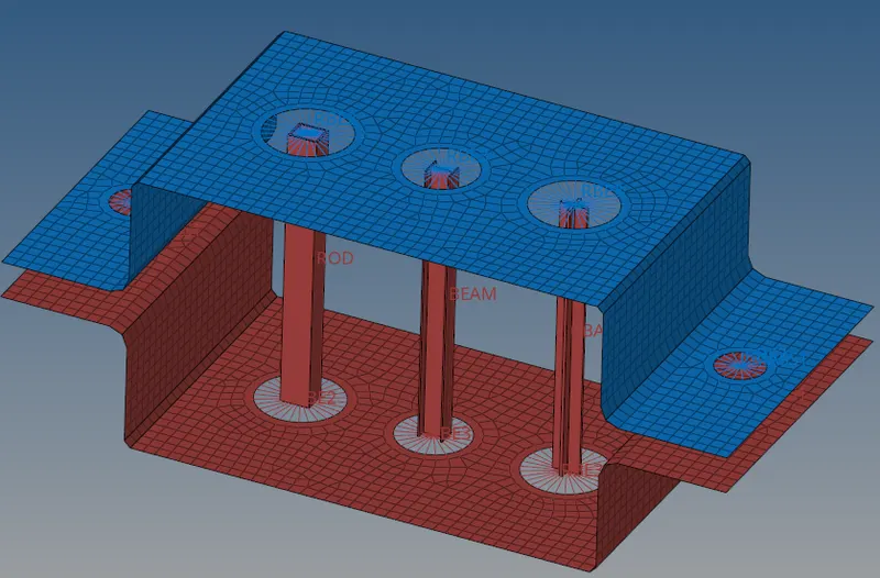
7. Join the two components with Spring elements.
No need to create or assign any property to spring. Elem types: CELAS1
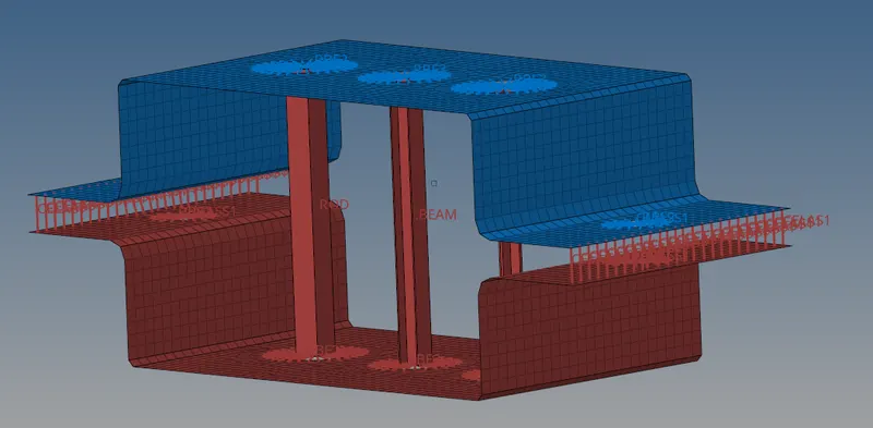
CONCLUSION:
- I Learned to create mid-surfaces of the components.
- Created rigid(rbe2) and rbe3 links.
- Created 1D elements(rod,beam and bar) with given dimensions and DOF.
- Assigned masses to the rigid links wherever asked in the question.