Week 6 Fuel cell powered vehicle model
Problem Statement - Explain the working of the power_fuel_cell.slx model.
Theory -
The model -
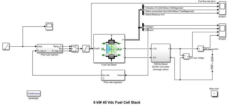
The hydrogen activated to form the proton ion with the catalyst is injected in the Proton exchange membrane fuel cell (PEMFC). When the electron is forced to flow out, the proton passes through the membrane and produces electric energy. The electron interferes with the oxygen as the electron returns back to the cathode. The proton ion turns into water.
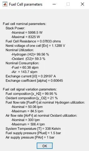
The fuel cell stack nominal voltage is 45Vdc and the nominal power is 6kW. The converter is loaded by an RL element of 6kW with a time constant of 1 sec. The cell parameters are as follows -
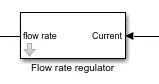
The load draws the voltage through a 100Vdc DC-DC boost converter. The flow-rate to the fuel cell is regulated by a fuel rate regulator and fuel rate selector. The fuel rate regulator take parameters such as current, number of cells, fuel pressure and nominal hydrogen utilisation and runs it through a function to derive the value of flow rate. The value of current is actually a feedback signal received from the fuel cell for the previous value of current. The fuel rate selector's purpose is to switch between the two scenarios for this simulation. The first scenario -
At t = 0 s, the DC/DC converter applies 100Vdc to the RL load (the initial current of the load is 0A). The fuel utilization is set to the nominal value of 99.56%.
and the next scenario
At t = 10 s, the fuel flow rate is increased from 50 liters per minute (lpm) to 85 lpm during 3.5 s reducing by doing so the hydrogen utilization.
To switch between these the selector uses two elements majorly - sample and hold and switch
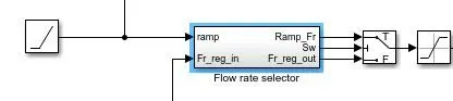
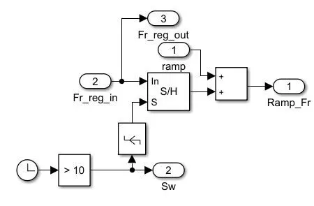
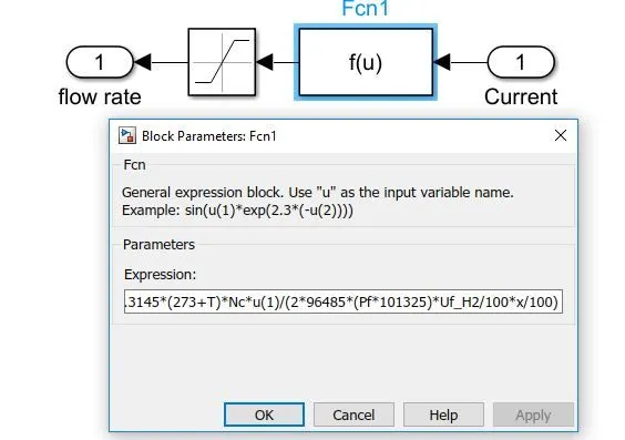
The input 1 to sample and hold is the signal produced by the flow rate regulator and the second input is the edge detector block which detects a rising edge in the output of the compare to constant block which in turn is waiting for the time decimation value to become greater than 10s for it to output 1(true). How the sample & hold function is, the output follows input 1 (In) as long as input 2 (S) is TRUE (1). The output is held when input 2 becomes FALSE (0). So after 10s the input(2) in our case becomes true and the Fr_reg_in signal starts flowing through the sum block. till 10s it bypasses the sum block. The switch too works in a similar manner. The Fr_reg_in signal keeps flowing through input 3 of the switch till the the compare to constant block becomes TRUE(1) at which point the sum block output which consists of both the ramp signal and the feedback signal flows through to the fuel cell. The saturation block maintains the signal below 84.5 which is the maximum value of flow rate for the given fuel cell.