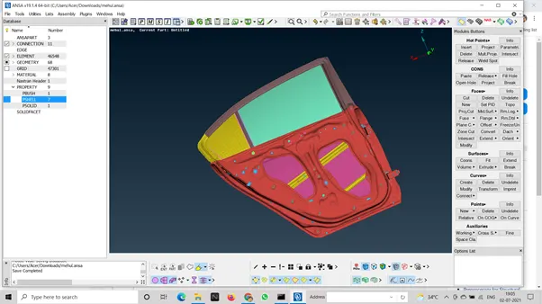
Week 6 - Creating connection for Rear door
AIM:- Defining degree of freedom and motion in the rear door.
PROCEDURE:- 1 we need to give different pids to all the parts which will make are connecting easier.
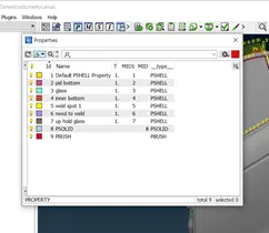
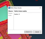
2 after create all the pids we need to look for single face holes and to fix it by using RBE2 option in NASTRAN module.
3 after finishing all single face hole fixing, we will look for two faces which are close to touching each other, go to topo module in points there is option of on COG.
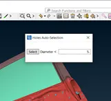
4 THEN SELECT EDGES OF THE SURFACE WHERE YOU WANT WELDING AND CENTER CLICK YOU WILL SEE A POINT APPEARING THERE, CLICK ON IT AND GO TO THE CONVERT OPTION
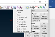
5 CHOOSE 3 D POINT A BOX WILL APPEAR.
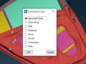
6 SELECT SPOTWELD POINT AND CLICK OK.
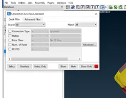
7 IN THE ASSEMBLY TOOL BAR CHOOSE CONNECTION MANAGER
8 a box will appear you need to select the spotweld point and click on enter.
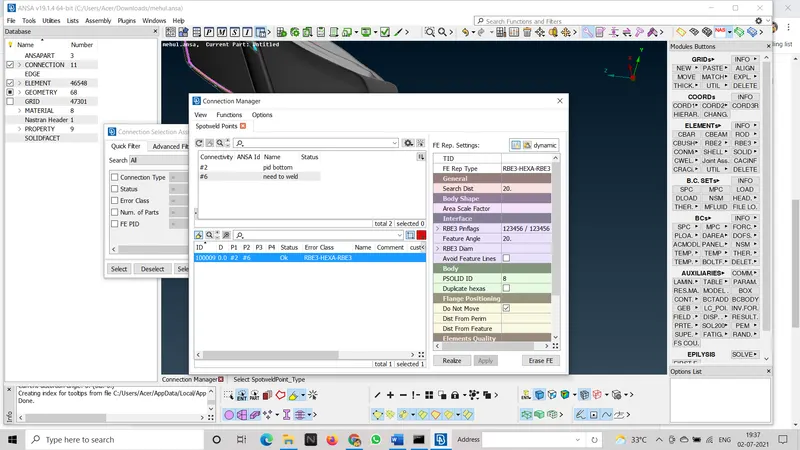
9 after enter another box will pop up in which you have to fill the details like which two surafce you want to weld what should be the welding perimeters. choose rbe3hexa rbe3 in fe rep type, you have to create psolid id in property manager.
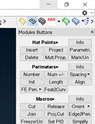
10 after performing this for all the parts which require welding we will shift our attention towards window, we need to go to the mesh module and select feature to curve option in the perimeters box.
11 select the edges of the window and press enter
12 you will see pink line on the edges of the curve.
13 now again go to the assembly tool bar and select convert
14 select curve in the option and mark the edges of the window, and choose spot line.
15 after this go to the connection manger in assembly tool menu.
select the curve and click enter.
16 a dialogue box will open where you have to enter all the details like which surface you want to join, and in fe rep type you should select rbe3 cbush rbe3, you have to create a pbush id for this connection.
17 after all the connection are done your model is ready for simulation.