Week 6 - Creating connection for Rear door
Creating Connections for Rear Door
Objective:
To create and apply different PIDs for different components for the given Rear door FE model and perform suitable connections without assigned thickness to FE. The intention is to deploy connections.
Procedure:
Here we have the rear door FE model, for which the connection should be rigid and should ensure the damping coefficient Of the physical model.
Connecting 2 different subsystems should be done manually and with 1 subsystem we can go with automatic bolt generation.
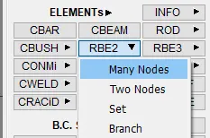
There are 2 types of RBE2 connection
- Single node rbe2(it connect 2 nodes)
- Many node rbe2
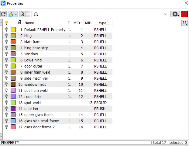
Initially, we defined separate PSHELL property for this FE model to distinguish between parts.
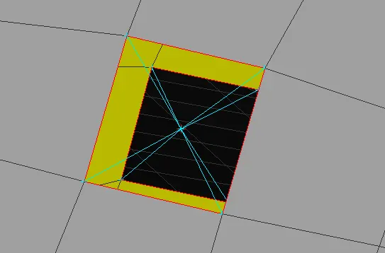
When we have to connect 2 parts rigidly we use the many node rbe2 type connection in the following manner
Select the node on that perimeter using the loop method for closed perimeter
Nut Bolt connection
In this, we use 2 nodes RBE2. For the nut bolt connection, there are 2 ways to establish this connection-
1. Manual - We simply select nodes of both parts and then define the stem of the bolt using a 2 nodes rbe2 connection.
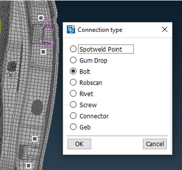
2. Using Connection Manager - Define 3d point using COG and then convert to bolt and realize bolt-type connection in the connection manager.
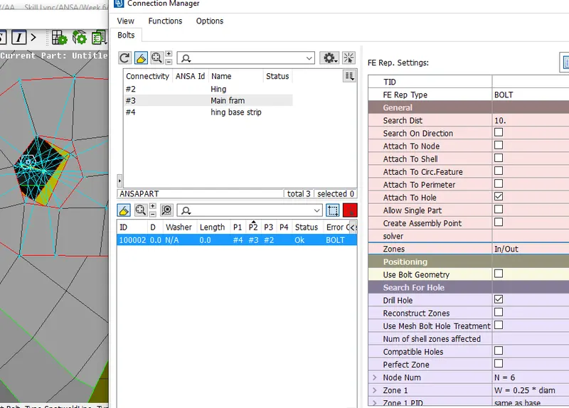
Now realize the connection by opening connection manager > FE rep settings > bolt > define the p1,p2 > FE representation type > Apply.
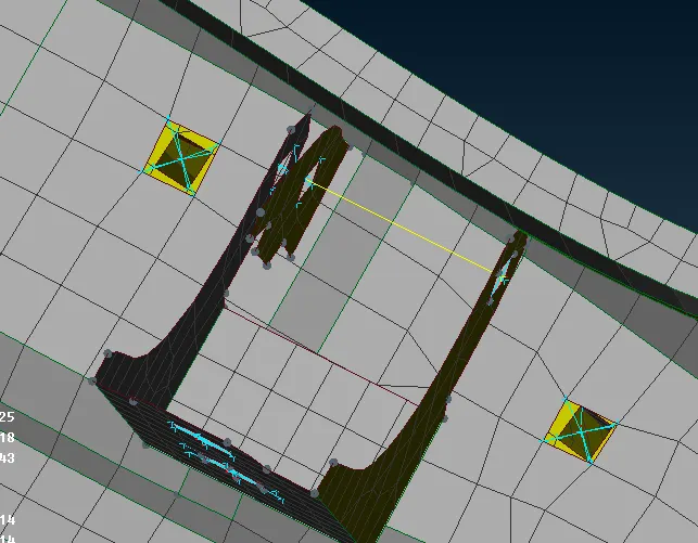
Since another hing connection is not available, we will be connecting it on the door hinges itself. This hing should not restrict all DOF as the door has to be open and close in a direction. So we have to remove the constrain along the global z-direction.
In this way, we established all the required connections for this inner panel of the door.
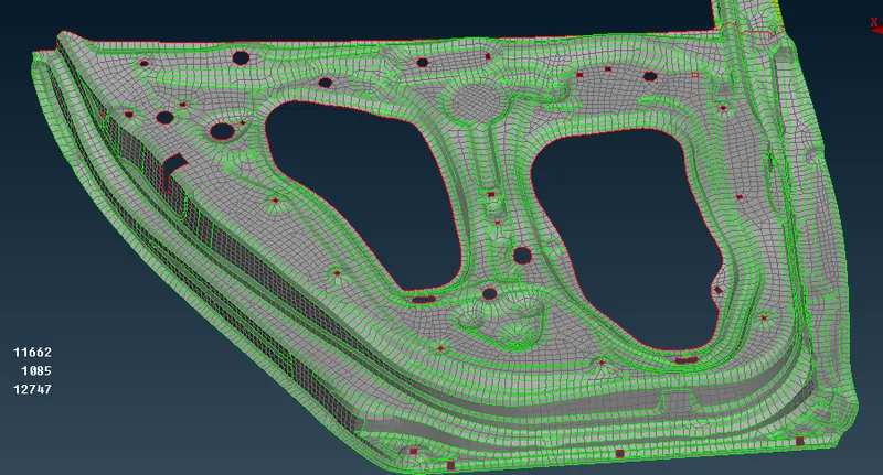
SpotWeld Connection
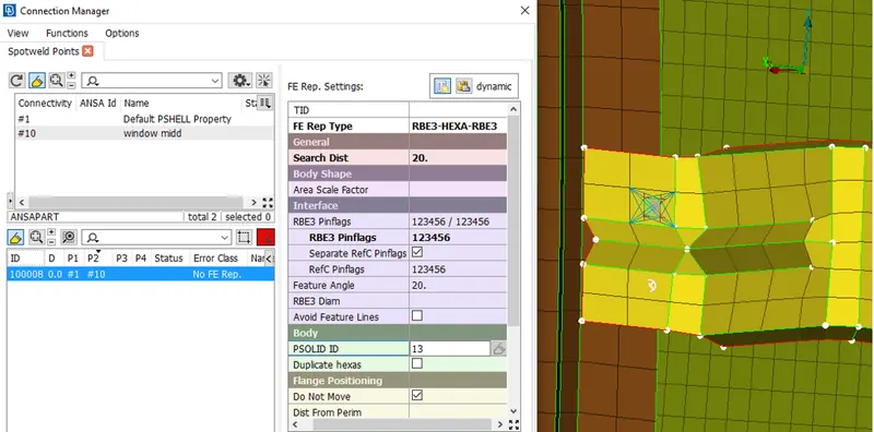
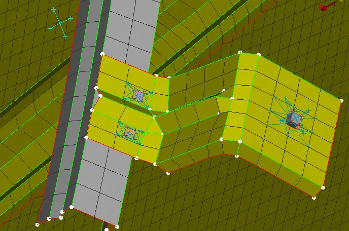
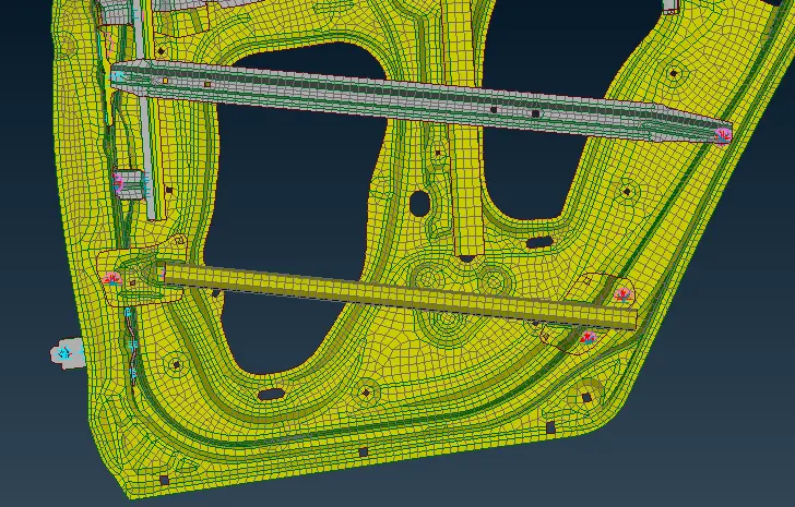
In this, we have to define a 3d point using COG and then convert it to spot weld and realize RBE3 HEXA RBE3 type connection in the connection manager.
we have to define a PSOLID ID here as well for weld material.
Handle Connection
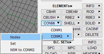
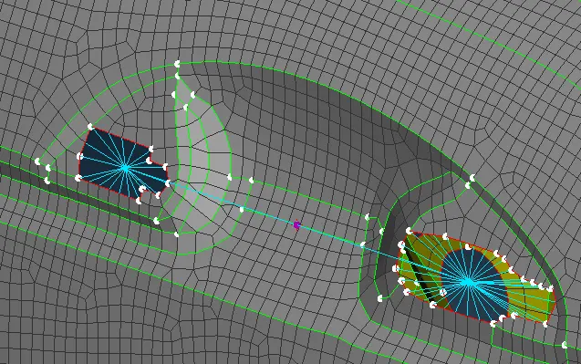
Capture this rigid in manny node rbe2 connection and at the master node of connecting rigid define a mass of 100gm in a tonne using con mass (Element > CONMI).
Weather Strip
This biding is on both sides in the lower bottom and goes to the upper side of a glass window.
First, deploy the connection lines which are on the window glass side as we have a damping element on either side of the door whereas other sides have only on the outer side of the door.
For that, we create a curve perimeter > Feat2Curve.
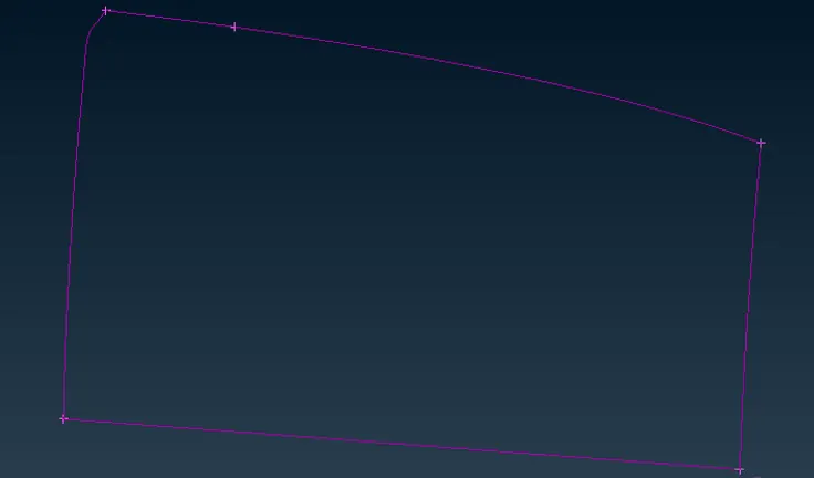
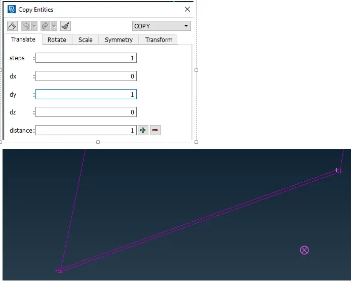
Convert the curve into the spot line.
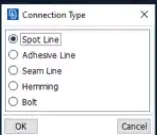
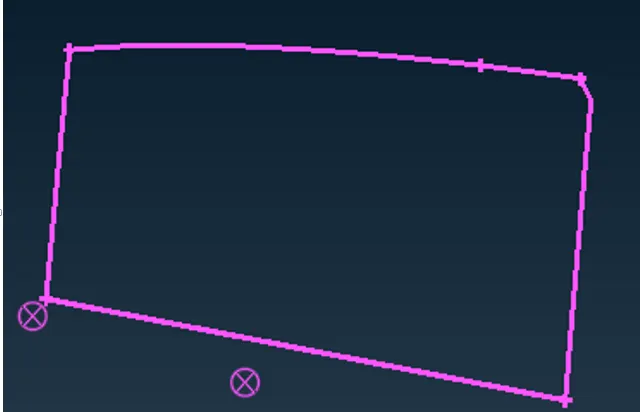
Going to the connection manager > RBE3 CBUSH RBE3. This CBUSH is a spring element that has a damping coefficient in 3 different directions this can be done by only one bush element.
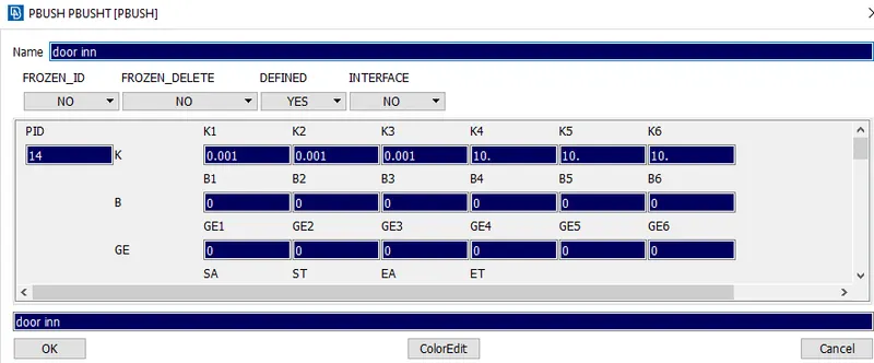
Now define the parts, give search distance, switch on keep all branches (as it will create min 3 nodes for rbe3 connection as best practice), and create a PBUSH ID.
Give 6 stiffness values and realize the connection. similarly, we do it for connection lines.
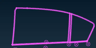
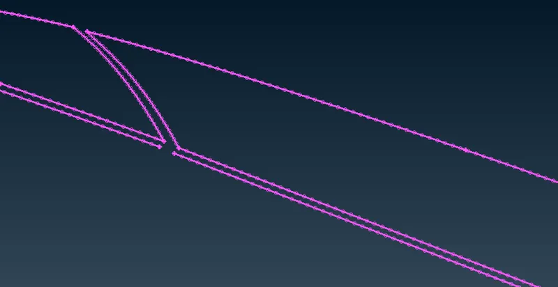
Due to the location or par connection and search distance. The vector direction orientation of the bush has changed that may affect our simulation, so it has to match with the global coordinate system.
For spot weld just how we have the RBE3 interfacing between the model and connector element similarly in the door connection the CBUSH has the RBE3 INTERMEDIATE TO THE body and CBUSH. Each CBUSH has an orientation vector and RBE2 elements are no property elements, whereas CBUSH has a critical property so it has a PID. Now, these vector orientation has to be aligned with the global coordinate which is initially due to different direction, location and search distance were have different local coordinate.
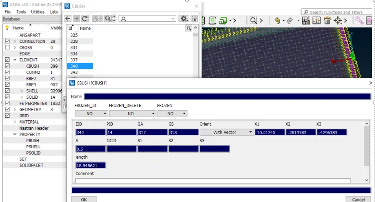
We have to give CID 0 for all bush connections.

Element > CBUSH >Go to orient and CID check > select all > modify.
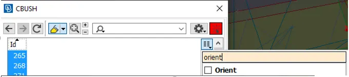
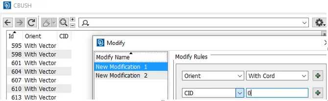
So now their vector attachment directions are different but the CBUSH are aligned towards the global axis.
Learning Outcome:
Learned the connections for the front door by using different 1D elements.
Confident in selecting the type of element for connecting certain parts of the door.
Conclusion:
Successfully created connections and applied different PIDs for different components for the given Rear door FE model and perform suitable connections without assigned thickness to FE.