Creating connection for Rear door in ANSA
AIM :
For the given Rear door FE model, Create and Apply different PIDs for different components and Perform suitable connections.
OBJECTIVE :
By using ANSA Software, Create and apply different PIDs for different components and to perform suitable connections.
PROCEDURE :
Importing a Model :
1. Import the given model by using the File-->open option.
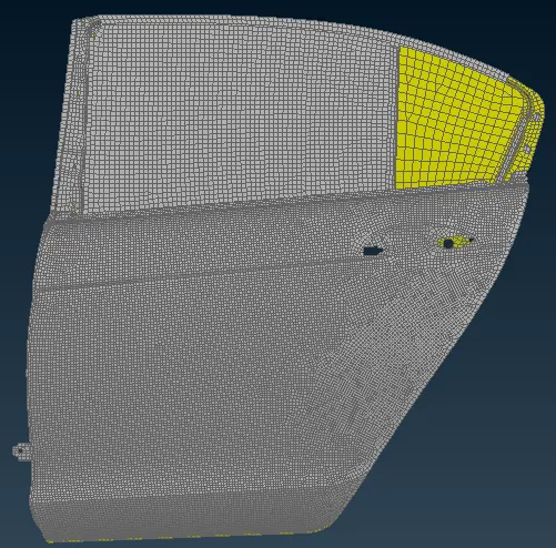
Fig: Side door
Creating PID :
2. Creating and applying different PIDs for different components.
3. Go to Mesh-->Macros-->Set PID option and select the Shell and create New-->PSHELL property for the selected component.
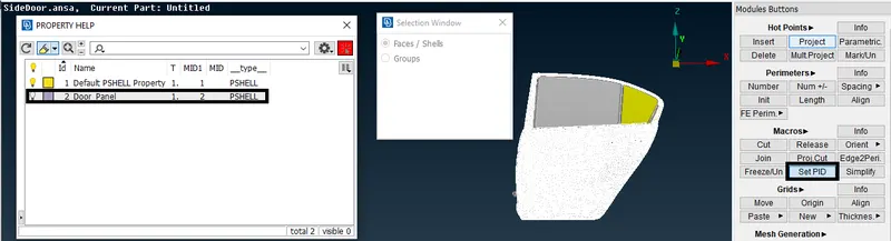
Fig: Assigning PID for different Components
Bolt Connection :
4. Go to Topo-->Points-->On the COG option and select edge to create a point.
5. After Creating a point, Go to the Convert option and select a point and Select a Bolt connection type.
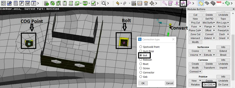
Fig: Converting Point to Bolt connection type
6. Go to the Connection option and Select the Bolt point and Click ok, Connection Manager window will open.
7. In the Connection Manager window, select the part to make a connection and set it as FE Rep type as Bolt, Search Distance as 20, and Zones as In/out.
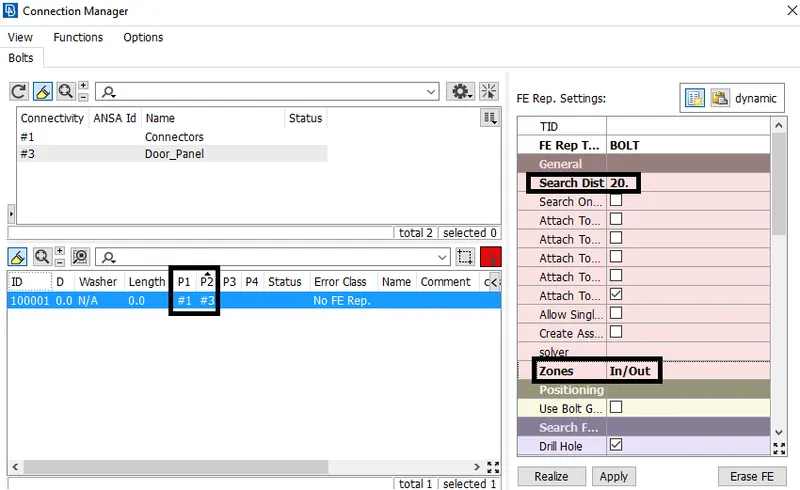
Fig: Connection Manager - Bolt Connection
8. After setting all in the connection Manager window, click apply & Realize.
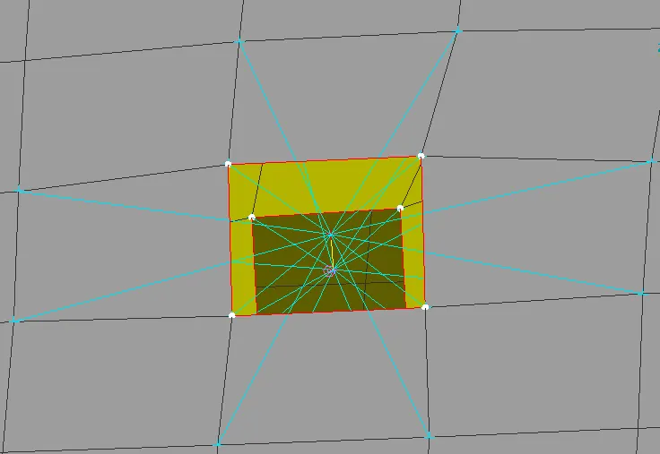
Fig: Bolt Connection
SpotWeld Connection :
9. Go to Topo-->Points-->On COG option and select edge to create a point.
10. After Creating a point, Go to the Convert option and select a point and Select a Spot Weld Point connection type.
11. Go to the Connection option and Select the Spot Weld point and Click ok, Connection Manager window will open.
12. In the Connection Manager window, select the part to make a connection and set it as FE Rep type as RBE3-HEXA-RBE3, Search Distance as 20.
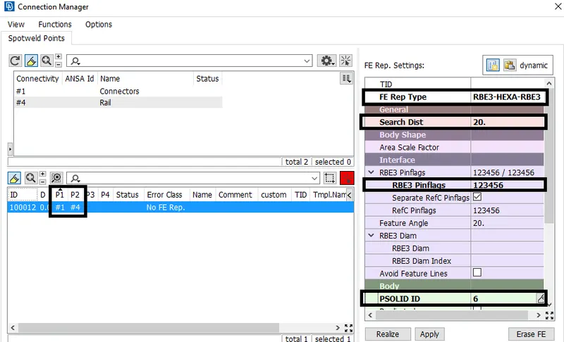
Fig: Connection Manager - Spot Weld
13. Set constraint in all DOF and Create PSOLID property and click apply & Realize.
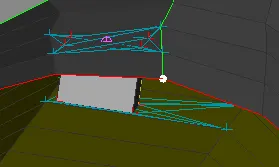
Fig: Spotweld Connection
CBUSH Connection :
14. Go to Mesh-->Perimeters-->Feat2curve option and select the edges and create a curve.
15. After creating a curve, Go to the Convert-->curves option and select a curve and convert to Spot line.
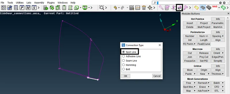
Fig: Converting Curve into Spot line
16. Go to the Connection option and Select the Spot Weld point and Click ok, Connection Manager window will open.
17. In the Connection Manager window, select the part to make a connection and set it as FE Rep type as RBE3-CBUSH-RBE3, Search Distance as 50 and Select Keep all Branches option.
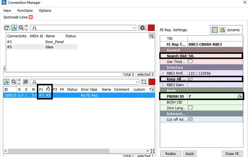
Fig: Connection Manager - CBUSH
18. In the Connection Manager window, Create a PBUSH ID and assign the values for the property.
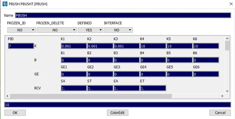
Fig: Creating PBUSH
19. After setting all in the connection Manager window, click apply & Realize.
20. After creating a CBUSH, Open the CBUSH window from Database and convert Orient as with Cord & CID as 0 for all CBUSH.
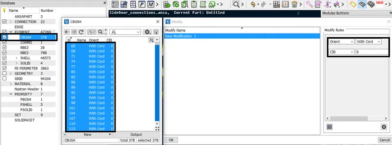
Fig: CBUSH Modifying Orient & CID
21. Finally CBUSH will be created along with the Global axis.
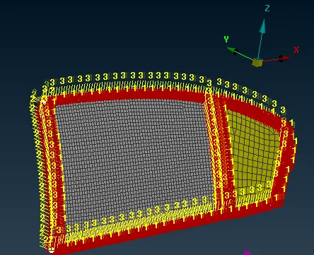
Fig: CBUSH Connection
RBE2 Connection :
22. Connecting all other parts by using RBE2 connection.
23. Go to NASTRAN DECKS-->Elements-->RBE2-->Many nodes Option and select the nodes and Create an RBE2 connection.
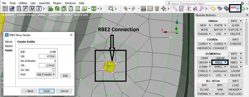
Fig: RBE2 Connection
Learning Outcomes :
- Learned to create a Bolt Connection, Spotweld Connection, CBUSH Connection, and RBE2 Connection.
- Learned to create and apply PID for different FE Components.
RESULT :
Created Different PIDs for Side door FE Model and Performed Bolt connection, Spotweld connection, CBUSH connection, and for all other Components used RBE2 connections.
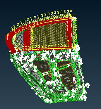
Fig: Side Door with suitable Connections