Week 6 - Creating connection for Rear door
AIM:- The objective is to perform suitable connections for the Rear door of a using ANSA software and NASTRAN deck.
PROCEDURE:-
1) Understanding the given door model.
2) PID checking of given model.
3) Set new PID for all parts.
4) Perform suitable connection at variuos loations.
Types of connections Used :-
I)RBE2 USING MANUAL METHOD [CLUSTER METHOD AND MULTI-NODES/TWO NODES METHOD.
II)RBE2 CONNECTION USING AUTOMATIC METHOD OR COG METHOD.
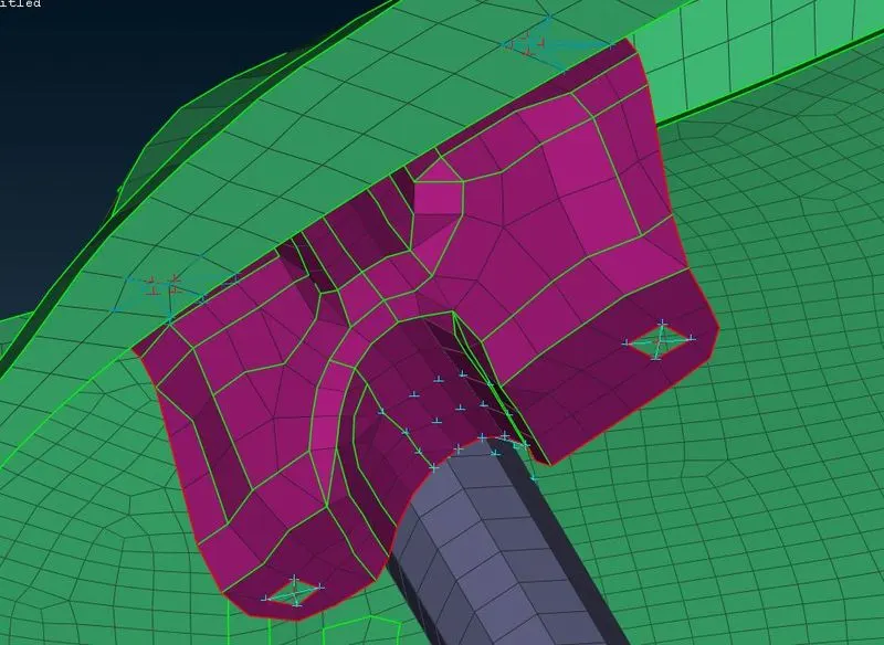
III)DOOR HANDLE CONNECTION USING CLUSTER RBE2 AND ASSIGNING CONMASS.
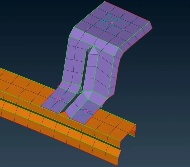
IV)HINGE CONNECTION USING TWO NODES RBE2.
v)SPOT WELD CONNECTION USING RBE3 HEXA RBE3.
vi) WINDOW CONNECTIONS USING RBE3 CBUSH RBE3
1) Understanding the given door model :-
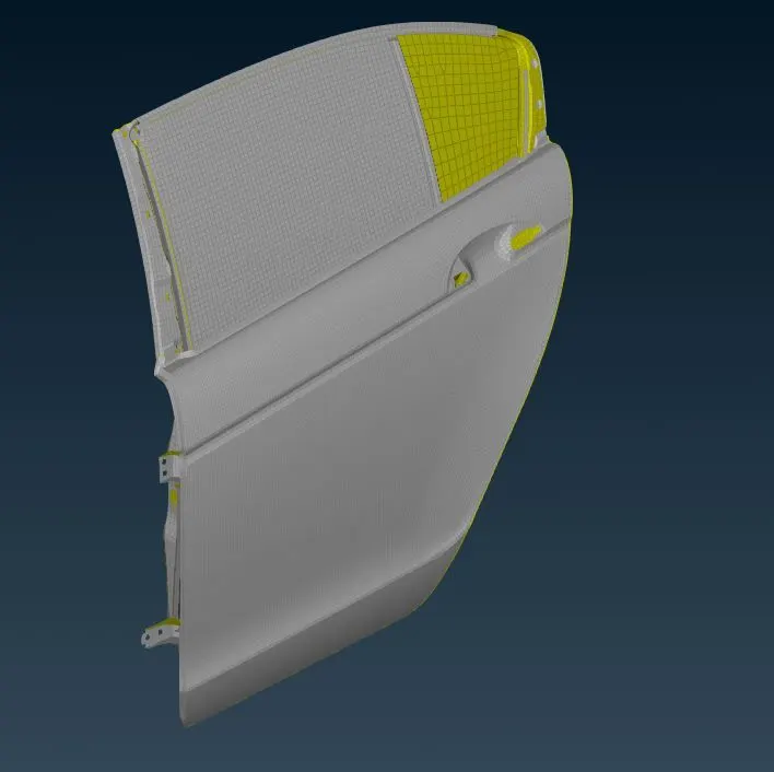
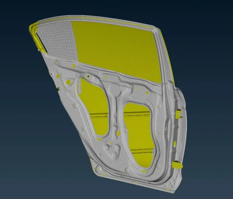
After opening the given model it was seen to have meshed completely. Inspection of the CAD model was done and no errors were found.
-Understand the type of connection at all location.
-Understand the tpye of mechanism used.
2) PID checking of given model
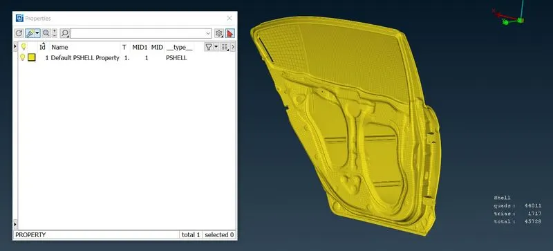
It is observed that, Complete door assembly is in 1 PID, need to set diff. PID all parts differently for better connections.
3) Set new PID for all parts. :-
-Isolate each part by using PID region option.
-set PID for each part by using set PID option.
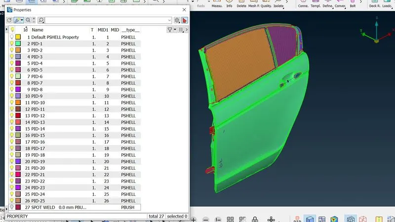
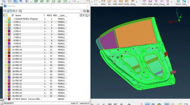
Total 26 PID is generated for all parts
4) Perform suitable connection at variuos loations.
- There are various ways in deploying connections. In brief, there is a manual method and an automatic method. The details of each connection is given below.
a] PERFORMING RBE2 USING MANUAL METHOD [CLUSTER METHOD AND MULTI-NODES/TWO NODES METHOD]
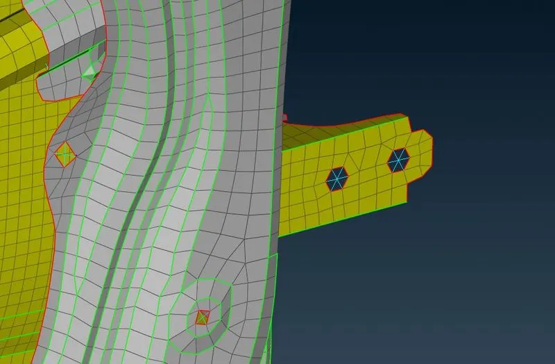
i] Performing RBE2 using multi nodes/two nodes method:
- RBE2 is known as rigid body element Type 2 which defines connections using the Master node and Slave nodes
- RBE2 is generally used for NVH domains.
- In the manual process the steps used are NASTRAN DECK>>RBE2>>MANY NODES>> SELECT THE MASTER NODE>> CREATE ENTITY >> CREATE ENTITY>> CREATE NEW PART ID >> Done
b) PERFORMING RBE2 CONNECTION USING AUTOMATIC METHOD OR COG METHOD/BOLT METHOD:
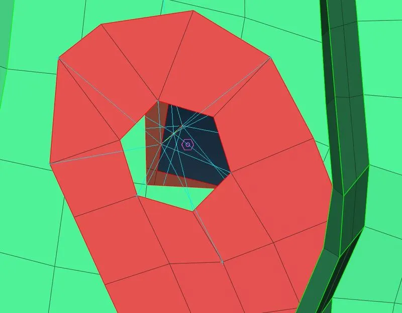
- This is also known as an automatic method as you can select 'n' number of holes and provide them connections in one shot with saving a lot of time.
- ON COG creates a 3D point on the centre of gravity of the selected curves, cons or elements edges. If any one entity is selected, The 3D points define its centre of Gravity.
- Bolt is a rigid representation to apply this method go to TOPODECK>> POINTS >>ON COG >>CLICK OK>> CONVERT>> 3D POINTS>> SELECT ENTITY>> BOLT>> OK>> CONNECTION MANAGER>> SELECT BOLT>> SELECT PROPERTY 1 AND PROPERTY 2>> SELECT FE REPRESENTATION TYPE>> BOLT>> GIVE SEARCH DISTANCE>> APPLY>> REALIZE>> OK.
c) PERFORMING DOOR HANDLE CONNECTION USING CLUSTER RBE2 AND ASSIGNING CONMASS TO IT:
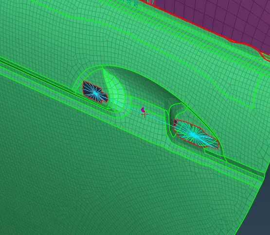
- Performing Door handle connection using cluster RBE2 and assigning conmass to it. The following procedure is used to perform this connection.
- NASTRAN DECK>> ELEMENT MODULES>> CONMi>> CONMi2>> NODES >> NEW TAB>> PROVIDE MASS VALUE OF 10 KGS IN TONNES ONLY>> OK
- CONMi defines a generally concentrated mass element connection represented as a sphere.
D) PERFORMING SPOT WELD CONNECTION USING RBE3 HEXA RBE3:
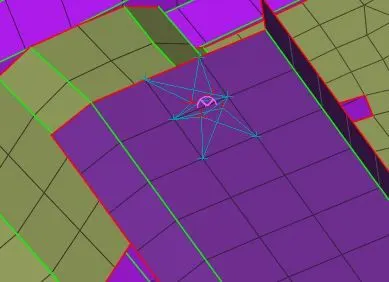
- RBE3 HEXA RBE3 is used to create the connection of the Hexa type of element that is solid volume.
- Steps>> ON COG>> SELECT ENTITY>> CREATE 3D POINT>> CONVERT>> 3D POINTS>> SPOT WELD>> SELECT PROPERTY 1 AND PROPERTY 2>> SELECT FE REPRESENTATION TYPE>> RBE3 HEXA RBE3>> GIVE SEARCH DISTANCE>> RBE3 PINFLAGS AS 123456>> APPLY>> REALISE.
e) PERFORMING WINDOW CONNECTIONS USING RBE3 CBUSH RBE3 AND ALIGNING THE COORDINATES TO THE GLOBAL AXIS:
i] ESTABLISHMENT OF SPOT WELD CONNECTION:
- The most critical connection in the whole door model is the window connection.
- The window is based on the UP and DOWN mechanism so it should not be constrained. Rather than windows, Its curves should be created and constrained.
- Two curves with 10 mm distance should be created as between this 10 mm gap the window is going to move.
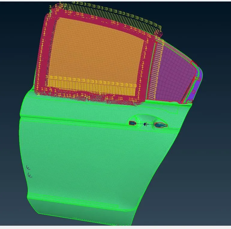
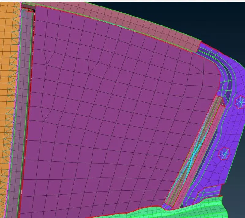
For rear glass of door using RBE2 connection :-
LEARNING OUTCOMES:
Following are the learning outcomes that can be learned by practising this model.
- Rigid Element: It is a link from one node to more nodes connected through master and slave nodes. The master node is the Independent node and Slave nodes are dependent nodes.
- RBE2 ELEMENTS: This element is a rigid body with six degrees of freedom specified at a single grid points.
- RBE3 ELEMENTS: RBE3 elements appear in ANSA as a set of cyan lines. The element defines the motion at a reference grid point as the weighted average of the motions at a set of other points. The reference grid point is the last one selected and is marked by a red cross. The set of the other points appears as cyan crosses. In form 3 elements the master node does not distribute the equal load to the slave nodes.
- Spot weld connections.
- Window door connection, Hinge connection and Door handle connection.
- Basics of Degrees of freedom
Link to download ANSA file :-
https://drive.google.com/drive/folders/1P7g-0yT_ik-CRd0pDJVRvkmdTyvyuujf?usp=sharing