Week 6 - Creating connection for Rear door
objective:- to perform the car door connection such a mirror , lover & upper support structure and other body parts in the door
procedure:- firstly we are uploading the geometry in the ANSA software
- Set the property ID for different part
- see the hole geometry for where we need joints and as well as find the area where we have to need a weld connection such as seam weld , spot weld etc.
- go on this area for making a bolt connection
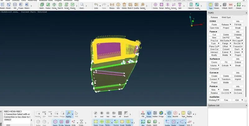
for creating a bolt connection on the side doon using the following step
first one go to the selection deck switch on the NASTRAN option
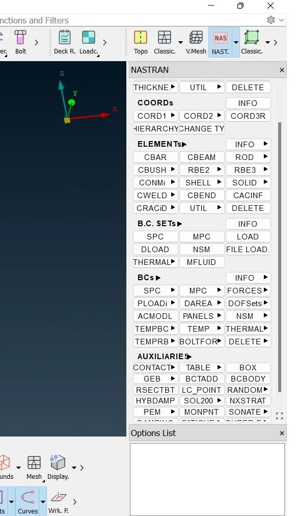
2. go to ELEMENTS --->RBE2 --> MULTIPOINT
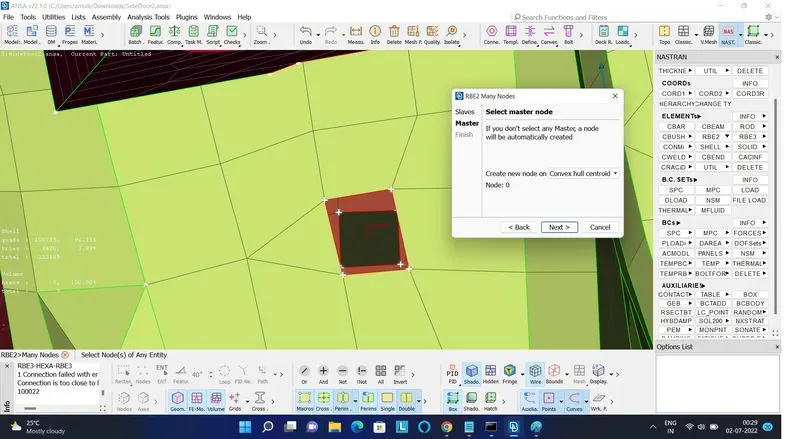
select the nodes on geometry where we want to create a bolt joint and then press middle mouse button and say next
now the net is forming around the bold area also do this thing with another bolt area hole then once we have a model point between the net we should go bolt connection
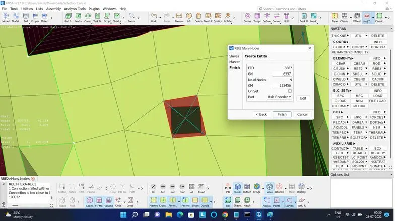
These are the manual method for creating a bolt connection
automatic method for creating the bolt connection
1. create a 3D point around the hole using ON COG option which are live on the topo modul ponit box
using the on cog option select a holle element bondry line we are also using this option with the fichture option such as fichture , loop or eles path options it was making easier for selection prosses
prsse the middel mouse butten than 3D point are generated on the space
2. convert this 3D point as a bolt use the convert option select the bolt option
3. go to the connection manager select the bolt point press the middel mouse button for confirmation.
creating spot weld on the geometry
1. before creating a spot weld point on the geometry make sure that the both part have different PID
2. go to ON COG point creat 3D point same as mentioned earlier
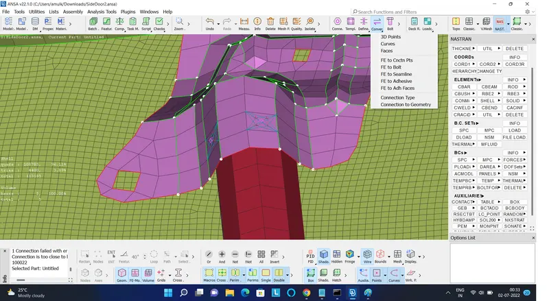
3. convert 3D point in the spot point by using covert option
4. select that particular point and go to the connection maneger. set the P1 and P2 value and also mention S value which are represent the sclar length of weld elements .
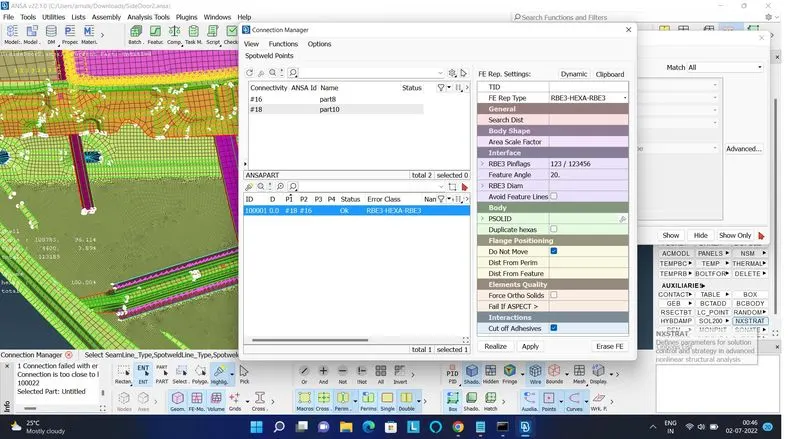
5 . go to FE ref. setting and select FE ref. setteing as RBE3 -HEXA-RBE3
give the seach distance as a 10 or 20 (depending upon distance between to body or elements )
6. here we need a new separate property ID whiche are shown as PSOLED this id besically use for soled work on the geometry like spot weld . so we are given a new PID
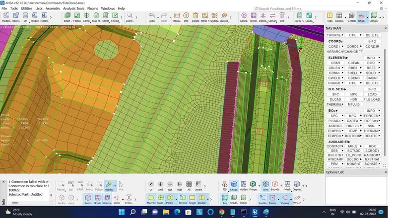
and now press the apply and say realize . and now we see spot weld are generated on the required surface
handle connections are made using RBE2 elements along with
CONMi>CONM2>NODES in order to give mass representation of the handle as tonnes
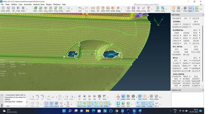
- connections for windows
- create curve around the perimeter of the window.
- transform them into spot lines.
- select the lines after opening CONNECTIONS MANAGER RBE3-CBUSH-RBE3 is used to represent Window Connections becausewindows are connected with soft bending to absorb shocks.
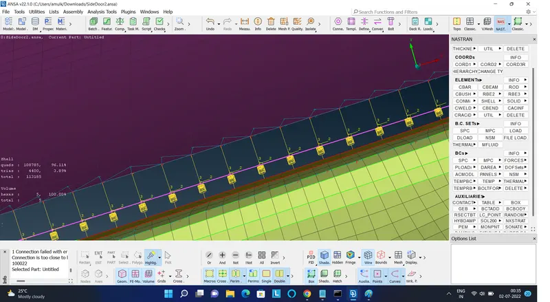
- Assign parts for connections of CBUSH elements.
- Repeat this for another window.
- change the co-ordinate to 0 in CBush Properties so it gets globally aligned towards one direction.
CONCLUSION:
- Rigid body element are connected.
- Spot welding component connections are made.
- CBUSH element are represented
- Mass of Handle is represented
- Degree of freedom assigned for hinges.