Week 6 - Creating connection for Rear door
Aim :- Now for the given Rear door FE model, Create and Apply different PIDs for different components. By using the same technique and the elements as shown in the video, Perform suitable connections.
Solution :-
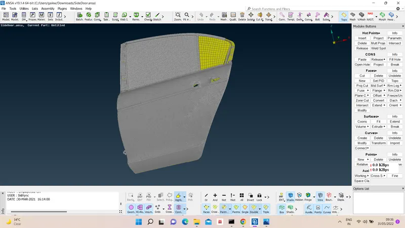
1) Import the door model -
Open model from file menu. We have to define different connections of doors as bolt,hing, weather strip, door handle, etc. We mostly gonna use Nastran deck for these operations.
2) To define RBE2 connection -
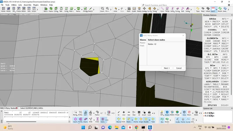
i) Many node - to define many node RBE2 conncection, first select RBE2 option from elements menu with many node. Then select slave nodes using one of methods of node slection like loop, then master node will be auto generated. Then create connection group for that part connection and ok.
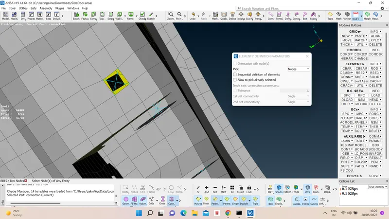
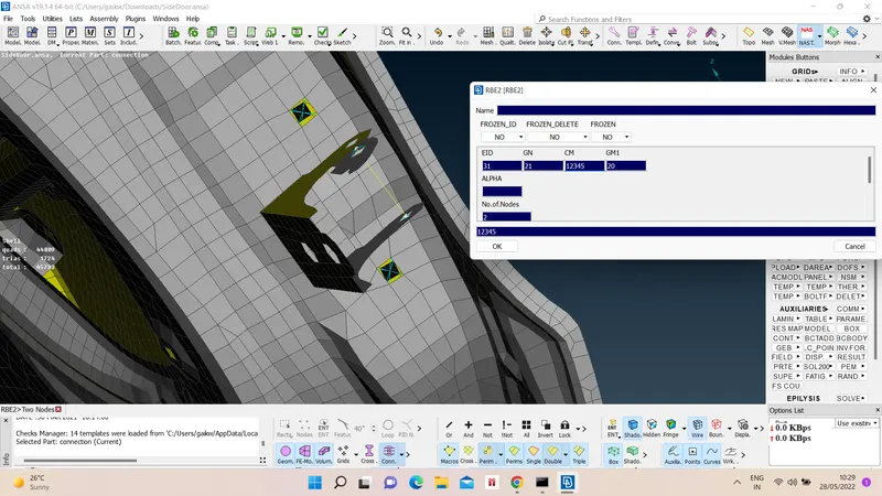
ii) Two node - This option can be used to define hinge connection or to define stem of bolt, etc. First select RBE2 two node option from elements menu, then choose two node and then similar procedure as for many node.
3) To define Bolt connection -
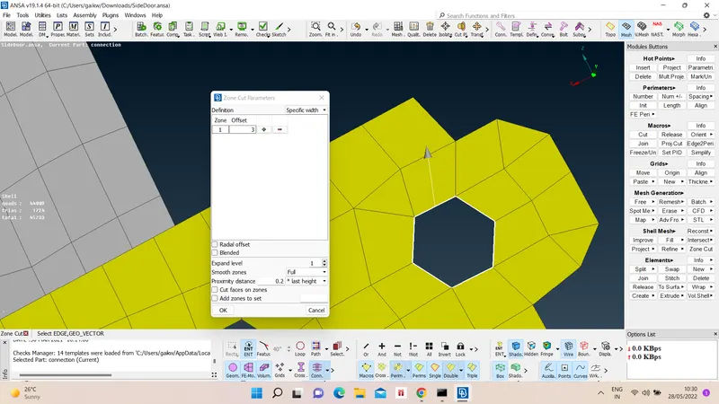
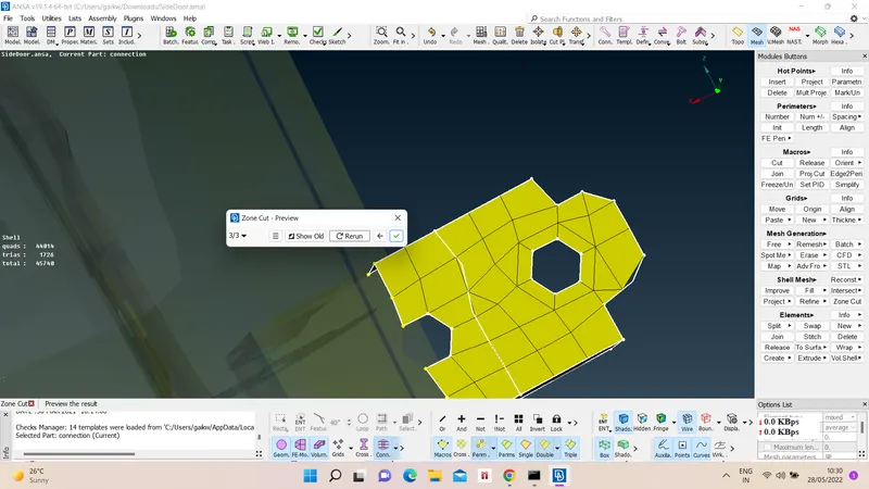
i) Washer - to define washer of bolt we used zone cut option like shell mesh - define zone - give offset distance - select hole - ok.
ii) Bolt - to define bolt head we select perimeter elements and give them RBE2 many node connection and same with nut too or sometimes we define cluster RBE2 connection.
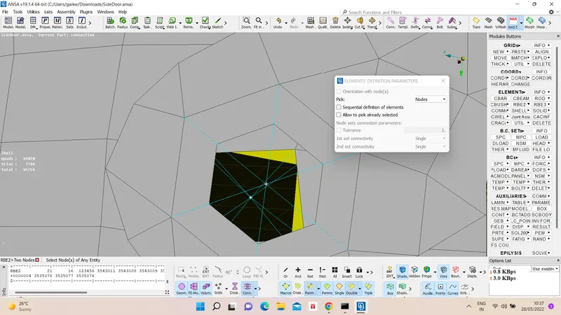
iii) Stem - to define stem we used RBE2 two node connection between bolt and nut master node.
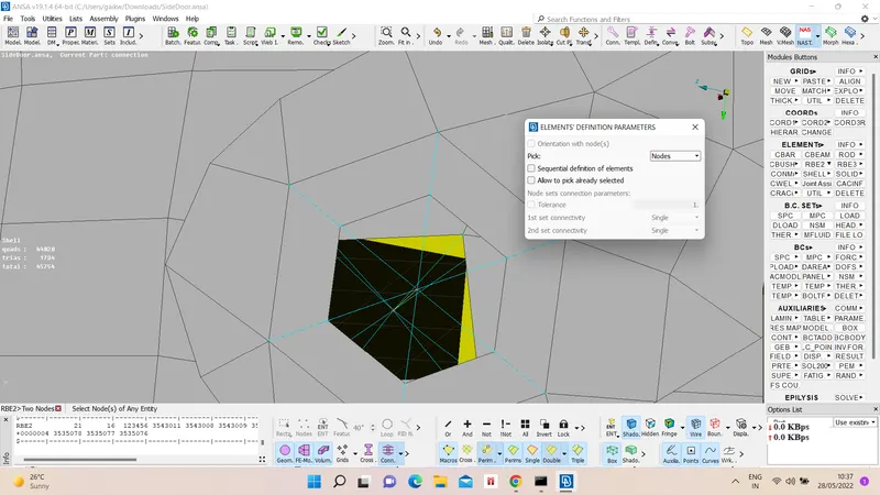
4) RBE2 cluster connection - to define attach components or parts we define them using RBE2 cluster connection as Elements - RBE2 - many node - select nodes of both parts - ok.
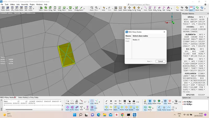
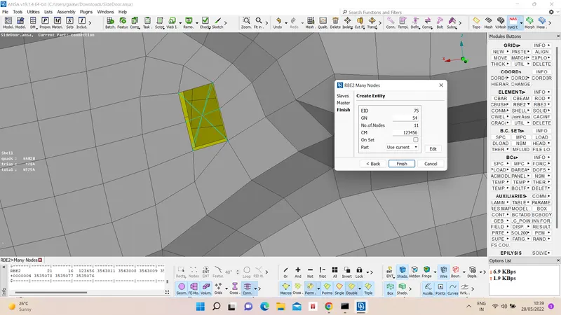
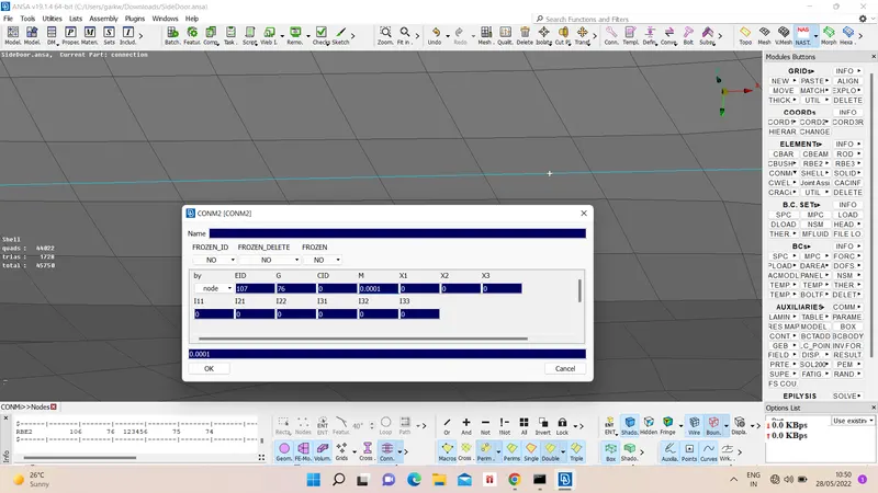
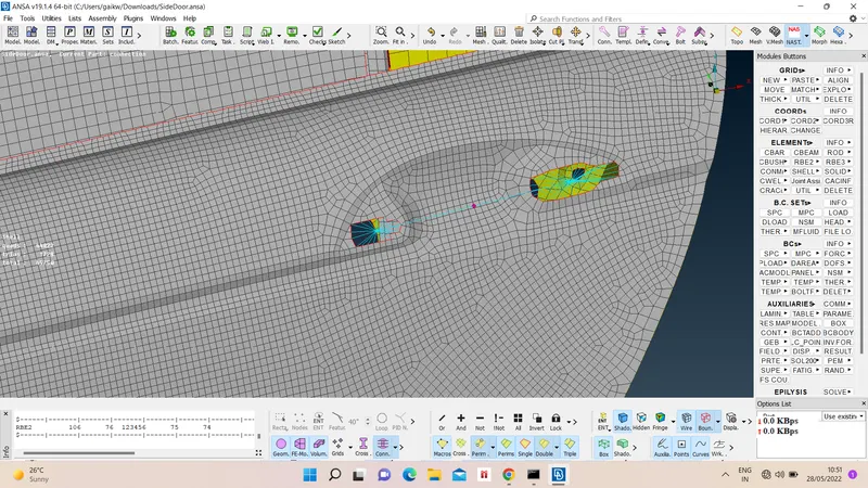
5) To define door handler connection - We capture door handle holes RBE2 many node connection and then capture the master node for handle holes. On master node we have to define the mass of handle, to define it Elements - conmi - conm2 - select node - give mass - ok.
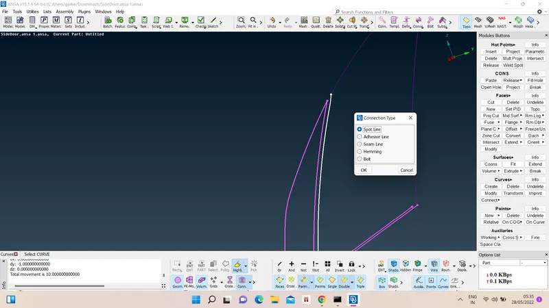
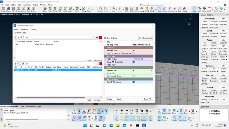
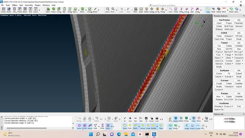
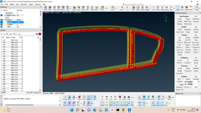
6) To define door windows/weather strip connection - We capture the outside of glass window as curve, the using convert option from assembly menu we convert the curve into spot line connection. Then open connection manager give appropriate FE rep type to spot line with all necessary data and confirm.
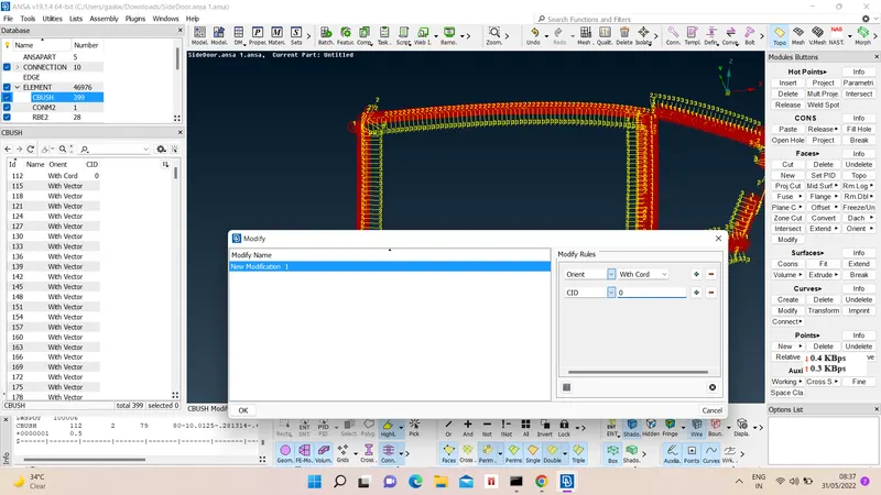
7) According to new rules orientation of Cbush connection should be with respect cord rather than vector, so to change it all at once open Cbush property id - visible orient and CID - select all connection- Modify - modify orient and CId - confirm.
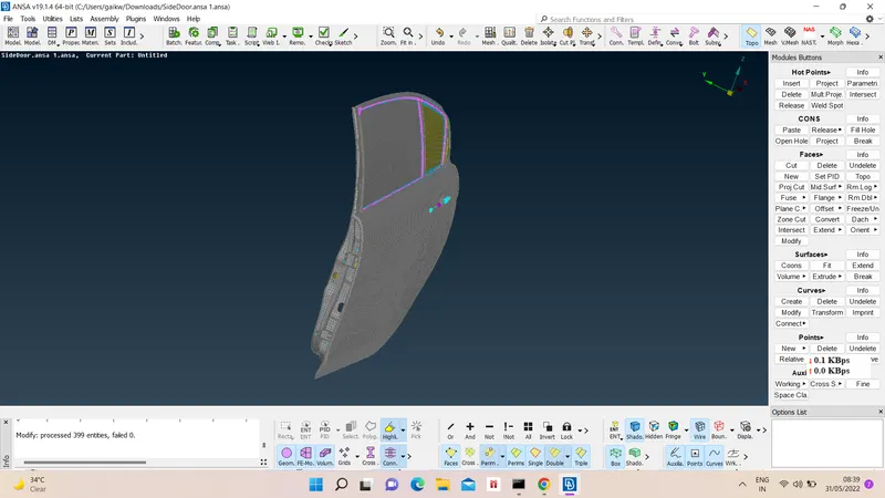
Final Product :-
G-drive link :- https://drive.google.com/file/d/1kuyaMKopIiJOYrrozEtOJ7rwbGxKI8Nr/view?usp=sharing