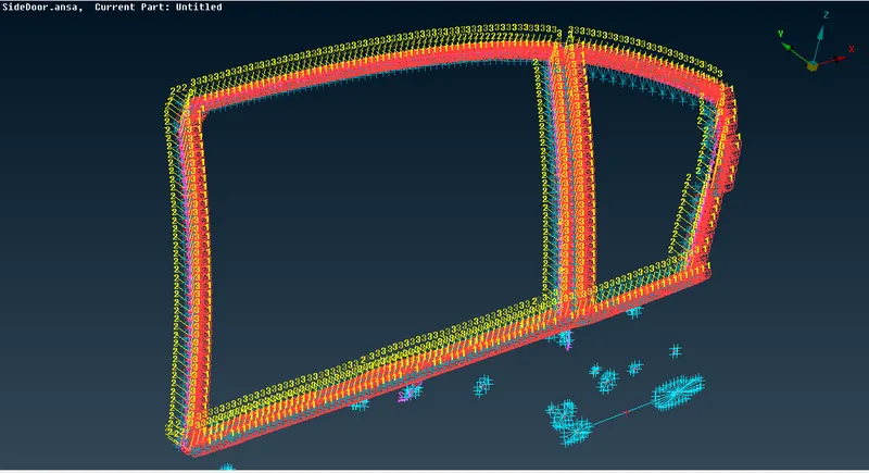
Week 6 - Creating connection for Rear door
AIM:For the given model distingush properties and give all 1D connections where ever necessary
PROCEDURE:
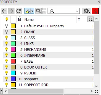
- initially divide the model in different properties as shown
- Now, give all the 1D RBE2 connections
- this connections can be given in may ways, as loop, quad angle,hot points
- if you have to give connections to a closed structure use loop for simplicity
- RBE2 can be given as both many node and two node select baased on need
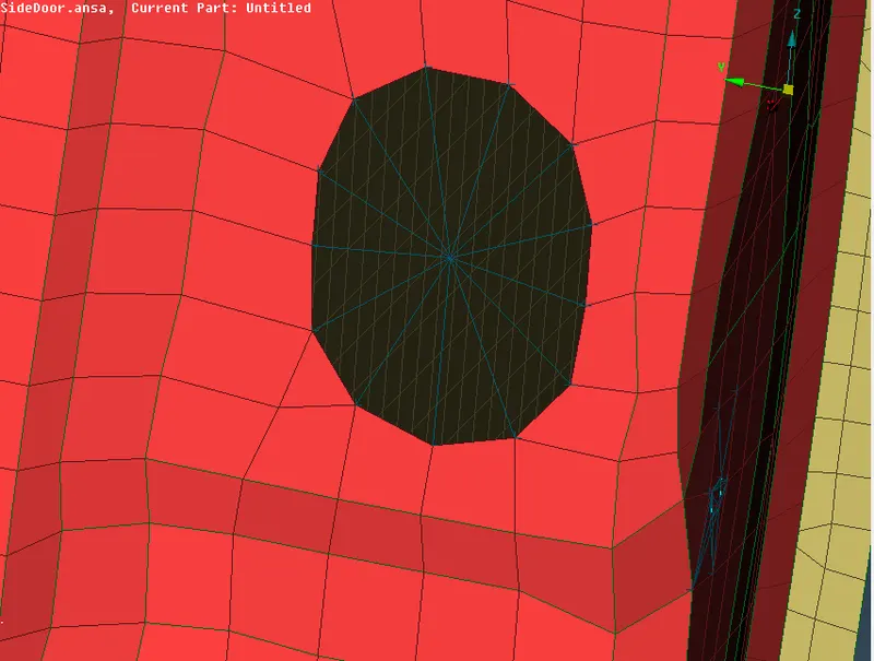
- go to many mode and select the hole as shown
- IF there is bolt connections that connectiong the 2 or more parts this can be done by, using connection manager
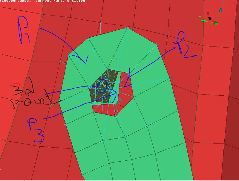
- firstly create a 3d pint and define this oint as bolt > connection manager.>bolt> select p1,p2,p3 and specoft the distance as shown
- check the entire figure visualise the entire model of the door and find out where links we persent where bolts are present and also the mechanisms
- one such type the door hinges there we should not arrest all the DOF we have to release the rotating pair as give only 12345
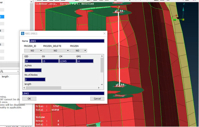
NOTE: also this connection is given thrught the RBE2 single node manager
Now lets move the next type of connection i,e. spot weld type
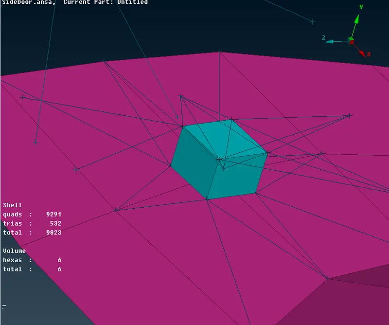
- for the spot weld we have to define a 3D point as spot weld point
- connection manager> RBE2 HEXA RBE2> define p1 and p2, spacing distance and define a PSOLID property for the weld material
SEAM WELD
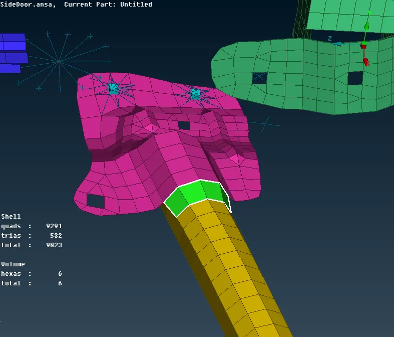
- create a curve from cones to curves option
- define this curve to seam line
- there are two types of seam weldings conditions
OVER LAP SHELL( if parallel)
Y- JOINT SHELL ( if perpendicular)
- in this model we all parallel types so we will use the over lap shell
- define p1 and p2 and also the base plate
- a specific property will be defined as a seam weld that will pop up in the data base
RIGID CONNECTIONS:
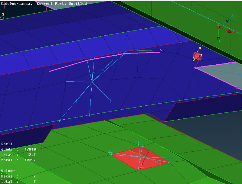
all the parts of any model are not made of same material , a mixture of materials are present as plastic , sheet matel etc....
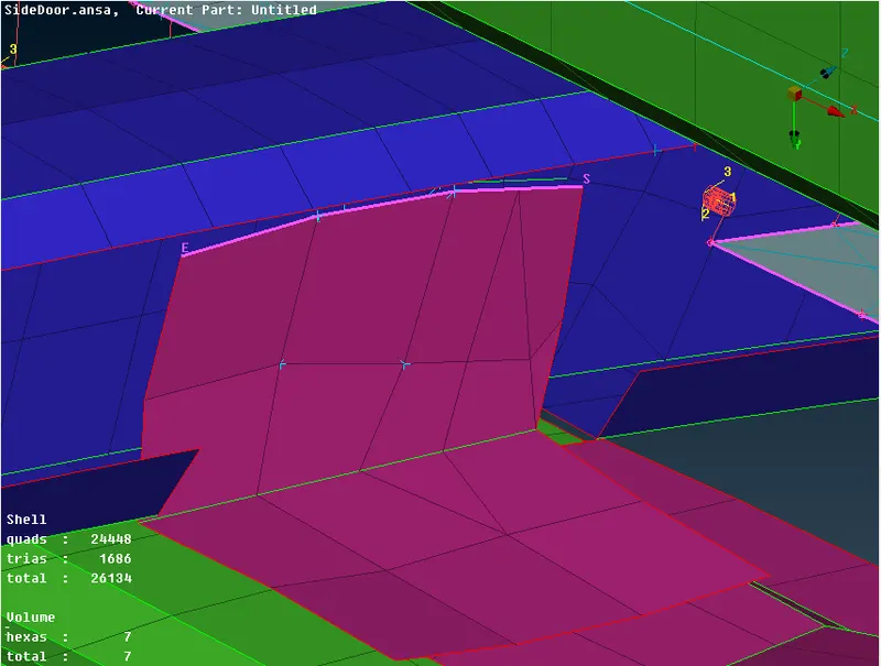
here there are glass and rubber straps are present at a joint so we can give a rigid connection as shown
BUSH CONNECTIONS:
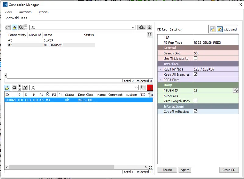
- FE to curve >define the curve as spotline
- connection manager>define p1 and p2 and spacing value as 10
- RB2 PBUSH RBE2> All branches
- give a pbush property and define in the property id tool an realize
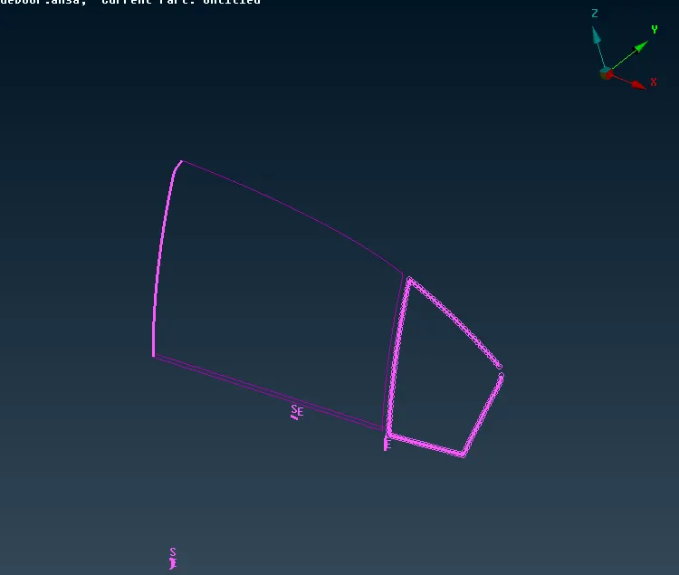
the final connectiona are as shown
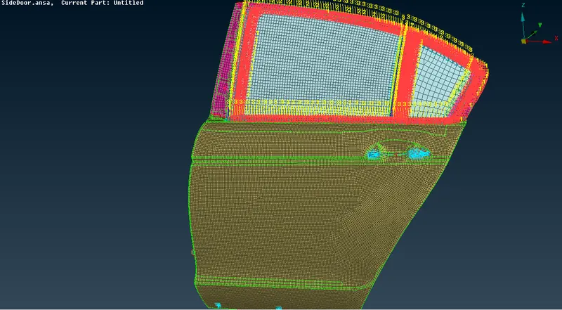
here all the pbush connection are in diffrent direction based on respective co ordinate system so we have to define them to a global co ordinate system by setting the the oriention and Cordinates to zero then they allign themsekf to a universal or global co ordinate system