Week - 4 - 2D meshing for Plastic components
Objective: To extract the mid-surfaces of the given plastic component and perform mesh operation by assigining the thickness
Note: As the given component is a plastic one , thickness of the component will not be through out the component,So while extracting the mid-surface choose the most desirible method
Procedure:
- firstly import the component in the ASNA software
- now, examine the entire figure using the bullioun operations to get the accurate view of the component
- start taking the mid surfaces one by one
- while taking the mid surfaces assign them in the secquence( divide them into seperate components)
- Divide this component using SET PID function and manage your DATABASE
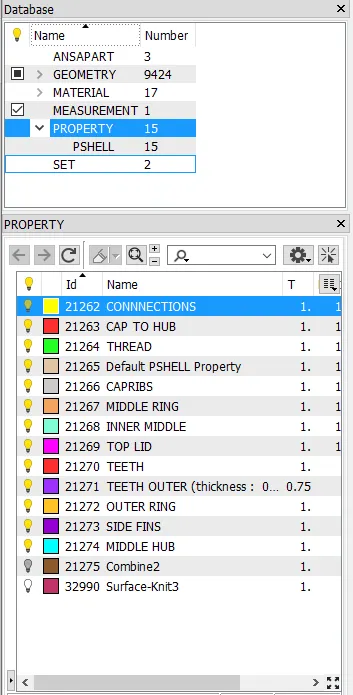
Now , lets start with the bottom ring, offset can be assigined based on convinience
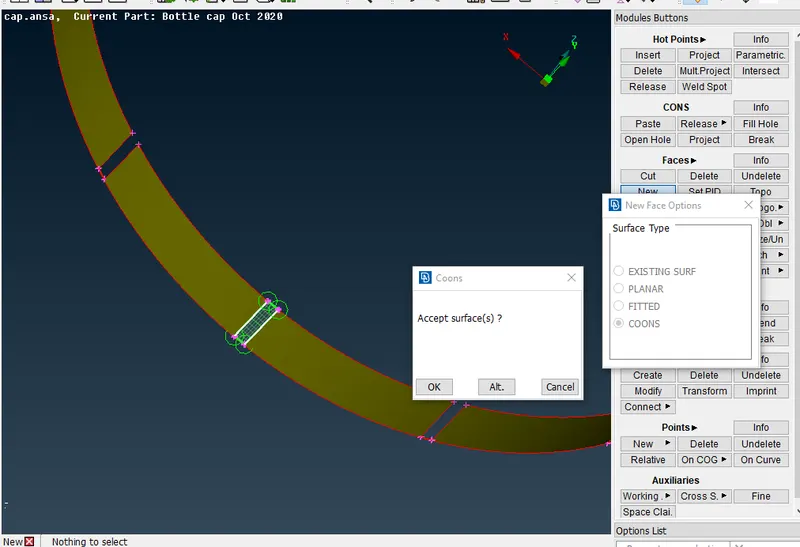
After extracting the offset,some geometric gaps are seen which can be filled by the NEWFACE options using coons
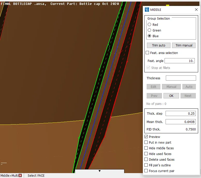
now extract the side fins by using multi middle option as shown
after extracting the multimids,a new property ID is set in the geometry we can use this or form a new PID
lets move to the inner teeth, here we can use rotate option taking only one mid we can assign all other mids
- for rotating we need to assign the centers for the rotation
- centers can be given bt COG option , by choosing circles aat different heights
- in the transom option set to rotate, pin the x and dx values with the center points respectively
- give the number of cpoing entites as n-1 and angle as 360/ no of entities in total
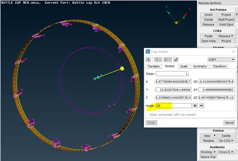
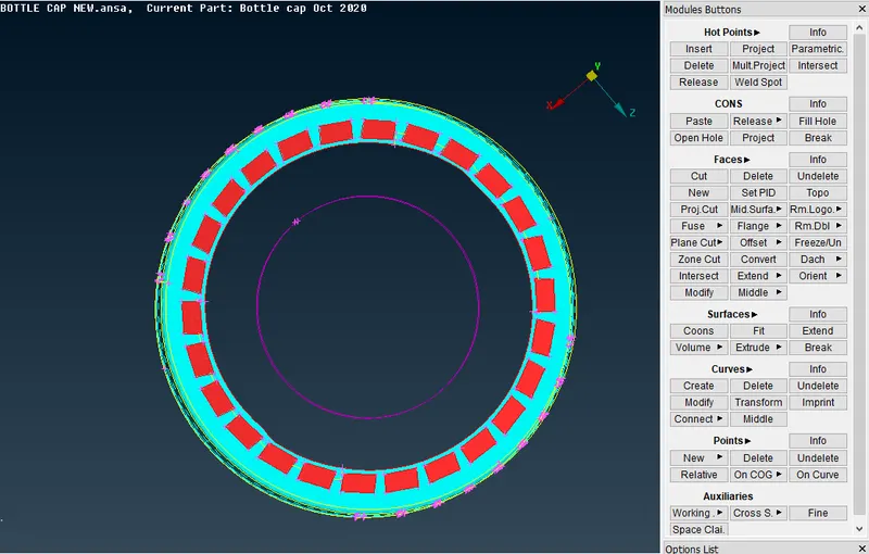
same follows for the inner teeth as well
now,between the middle hub and the bottom ring the fins should be in contact with them, this can be acheived by EXTEND , Highlighted in the figure
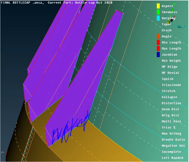
simillaarly , perform all the mid extractions using offsets, miutimids or by new surfaces and check their connectivity with each other
Now we for the thred, as it is a complex feature taking offset is impossibe so, we use the curve middle option to project a immaginery curve, which then we use to project on to the contacting midsurface(MIDDLE)
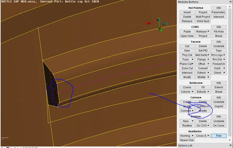
Project tis immaginary curve on to the presiding mid surface as shown
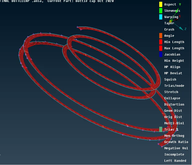
check all the mid surfaces once all the extractions are done one by one and make sure the connections are in tact with each other
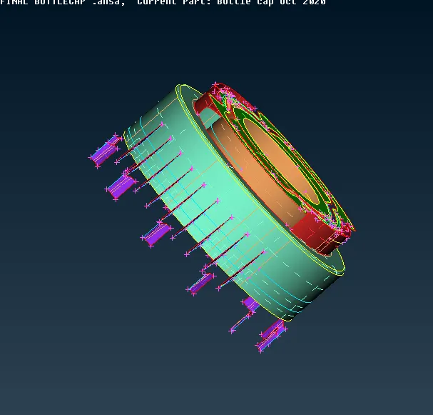
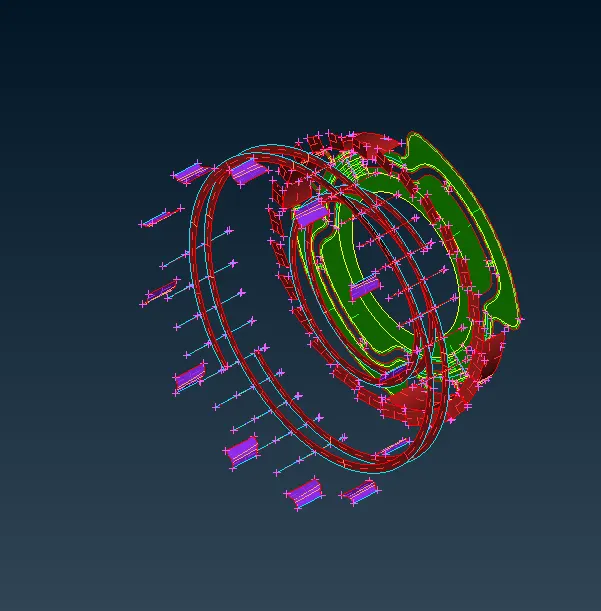
MESHING:
GO to the meshing deck and set the element size
- NOTE: this element size can also be assigined as in peroperty ID wise for easy visualization and handiling og meshing tools
- remove all unwanted hotpoints and construction lines, as it make the mesing difficut
use project curve for the geometric corrections
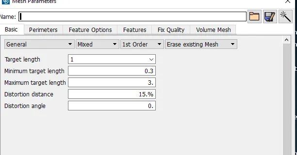
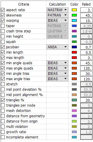
use project curves for the geometric corrections and mesh alterartions
- mostly use best option
- for mesh corrections mostly use reconstructions, else use split ans swap
- if any invisible skewness errors pop up go to topo delete face or change the shape of the face of propermeshing with out errors
- after the final meshing assign the thickness values , this can be done in the inital stage also
- make tria elments as minium as possibele
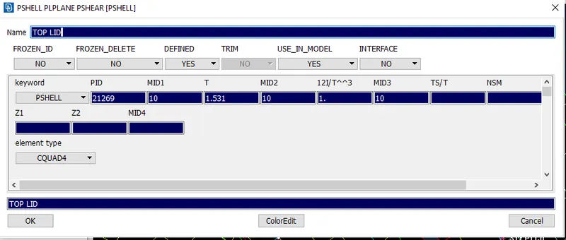
also we can change the colour as for our view
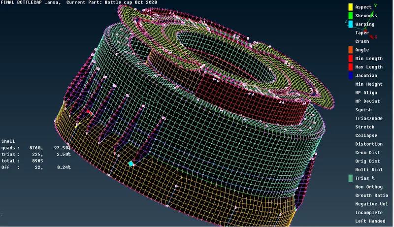
final meshing component is as shown in the figure below