Week 6: Conjugate Heat Transfer Simulation
Conjugate Heat Transfer Simulation
Objective: To conduct a conjugate heat transfer simulation through a pipe at different grid sizes and stage intervals of super cycling
Introduction: Conjugate heat transfer (CHT) involves the heat transfer analysis between solid and fluid. CHT occurs when heat conduction within solid body and heat convection in the surrounding fluid interact simultaneously. CHT problems are relevant in various domains of engineering including aerospace, nuclear, mechanics, meteorology, and biology.
At the interface of fluid and solid, the temperature and heat flux are continuous. But, the temperature changes rapidly. The fluid temperature is closer to the solid temperature near the solid, whereas away from the interface, the fluid temperature is closer to the ambient temperature of fluid. Thermal boundary layer signifies the distance where the temperature of fluid varies from the solid temperature to the fluid bulk temperature.
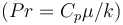
For the value equal to 1, thermal and momentum boundary layer thicknesses need to be the same.
At Prandtl number greater than 1, a thicker momentum layer is observed.
At Prandtl number lesser than 1, momentum boundary layer is thinner than thermal boundary layer.
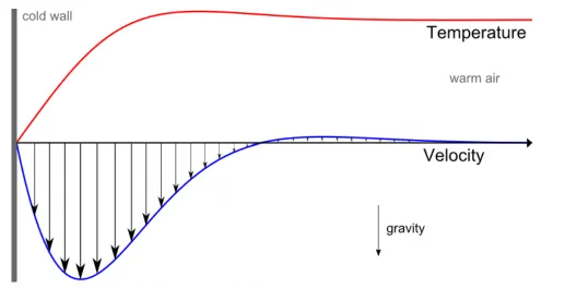
Velocity and temperature profile for natural convection of air near to a cold solid wall
Wall function
It is a crucial criterion to understand the approach required to solve near boundary wall.
No slip condition will be applied for laminar boundary.
For turbulent boundary, three regions can be defined based Y+ value.
· Turbulent layer: 30 < Y+ < 300
· Buffer layer: 5 <Y+ < 30
· Viscous sub-layer: Y+ < 5
Y+ value is used to estimate the height of first cell and tells whether to use wall function or not.
Y+ is calculated as:
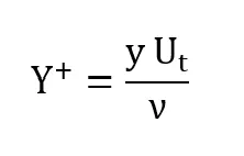
where y is the cell height, Ut is frictional velocity, and ν is kinematic viscosity.
Case setup:
Geometry preparation
Geometry is prepared for conjugate heat transfer problem which includes the fluid and solid region separated by the interface. The dimensions for the geometry are given below.
Inner diameter of pipe: 0.03 m
Total length of pipe: 0.2 m
Solid thickness: 0.01 m
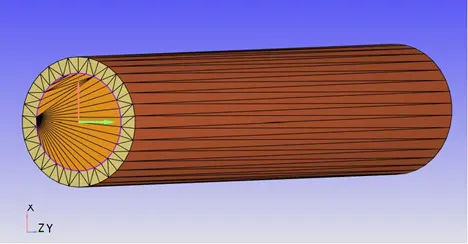
Geometry diagnosis
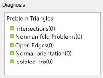
After resolving the geometry errors, such as non-manifold problems and normal orientation, diagnosis was run and no errors were found.
Boundary flagging
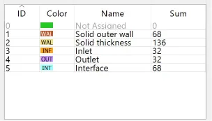
The boundaries were flagged as solid outer wall (boundary ID 1), solid thickness (boundary ID 2), inlet (boundary ID 3), outlet (boundary ID 4), and interface (boundary ID 5). The sum of triangles for boundary ID 1, 2, 3, 4 and 5 were 68, 136, 32, 32, and 68, respectively.
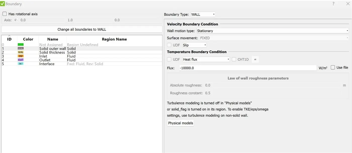
Boundary conditions for solid outer wall
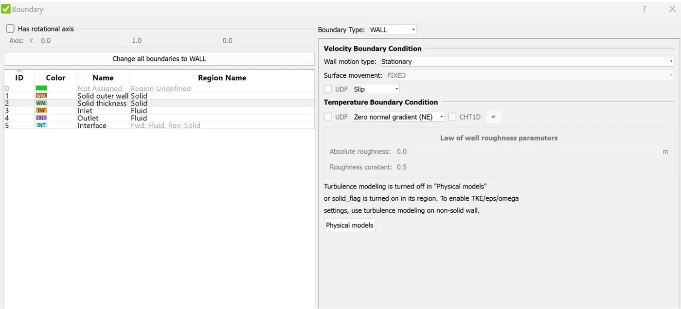
Boundary conditions for solid thickness
Boundary conditions for inlet boundary
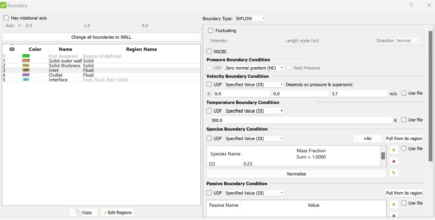
Calculation of inlet velocity:
Reynolds number, Re = 7000
Density of air (at 300 K), ρ = 1.17 kg/m3
Diameter of pipe, D = 0.03 m
Dynamic viscosity (at 300 K), μ = 1.86 x 10⁻⁵ kg/m s
Reynolds number is calculated using the equation below:
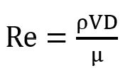
Hence, the inlet velocity is calculated as 3.7 m/s.
Boundary condition for outlet boundary
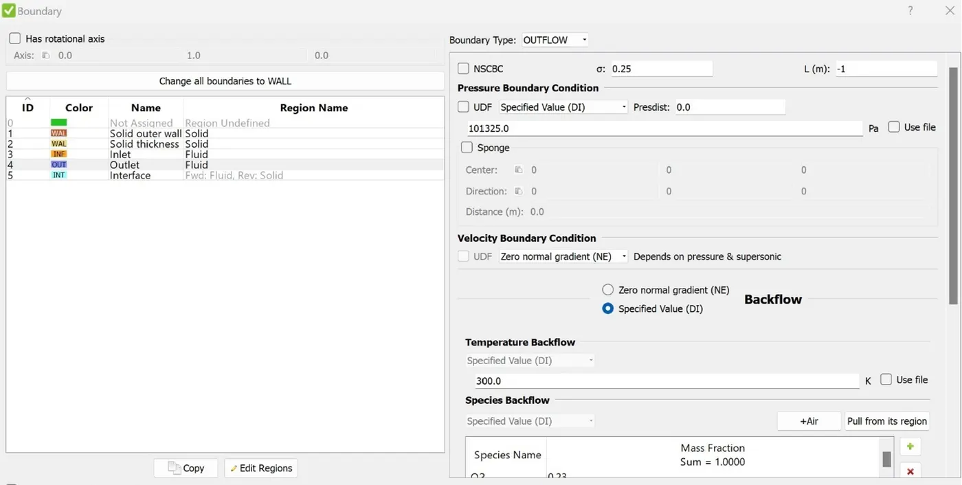
Boundary condition for interface boundary
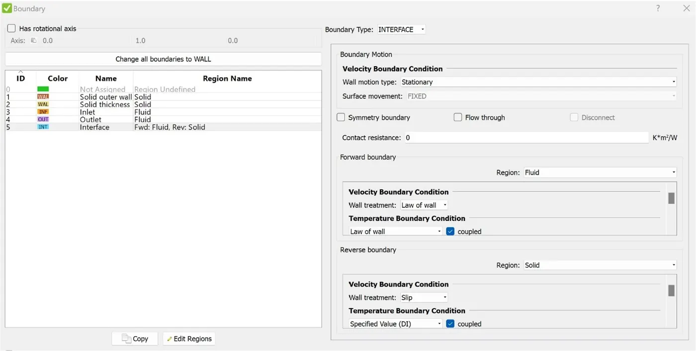
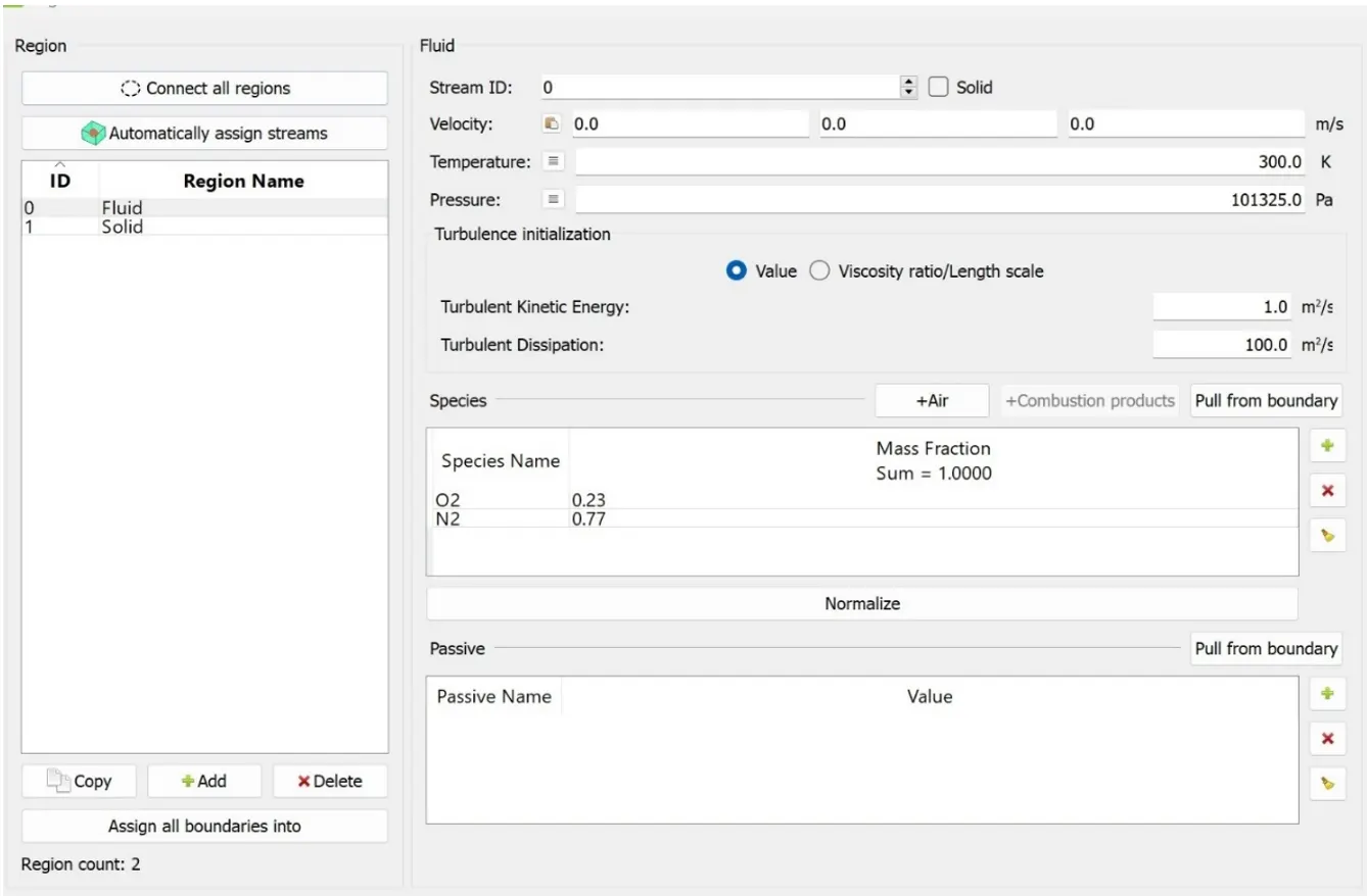
Initialization conditions for fluid region
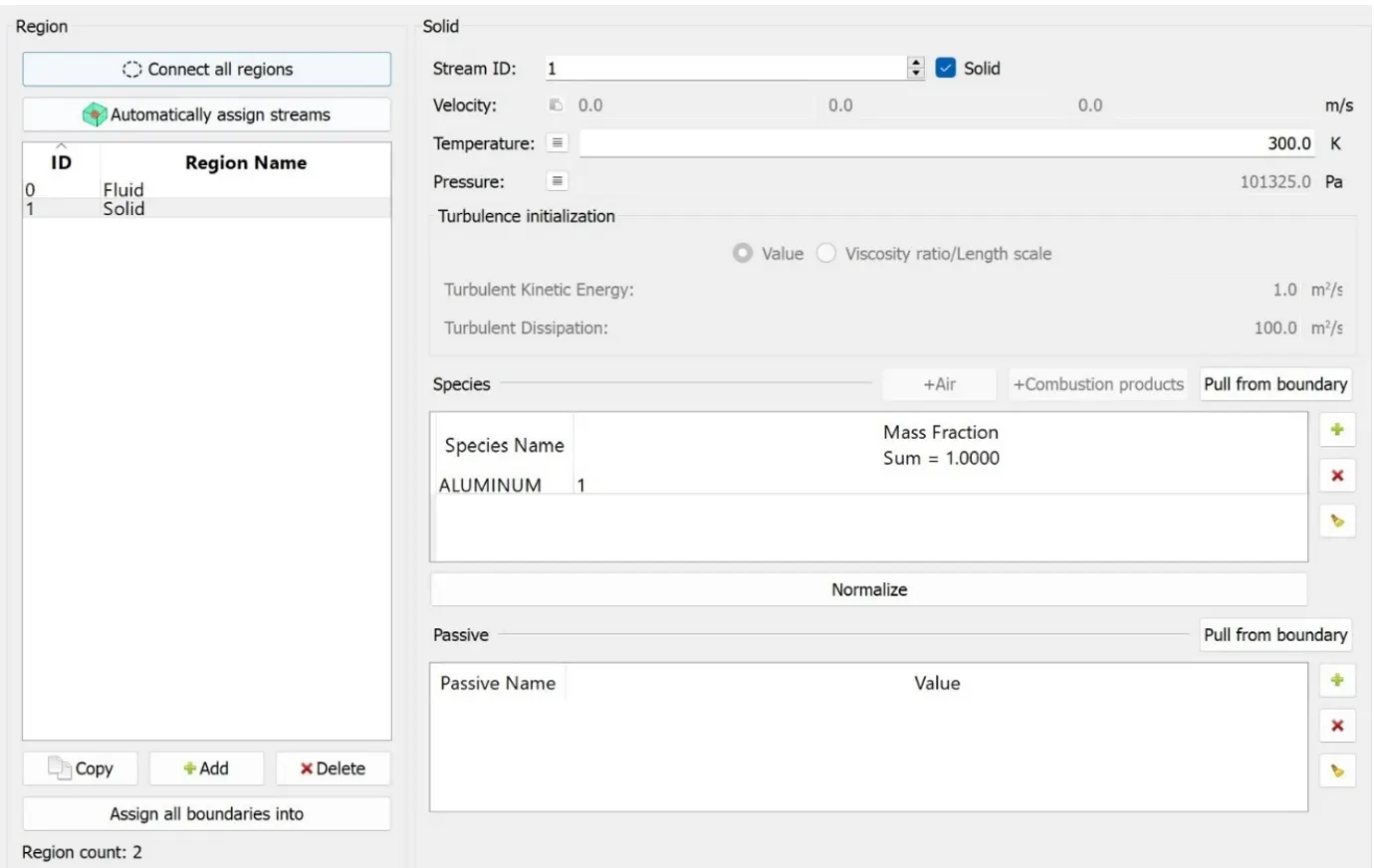
Initialization conditions for solid region
Details of super cycle model
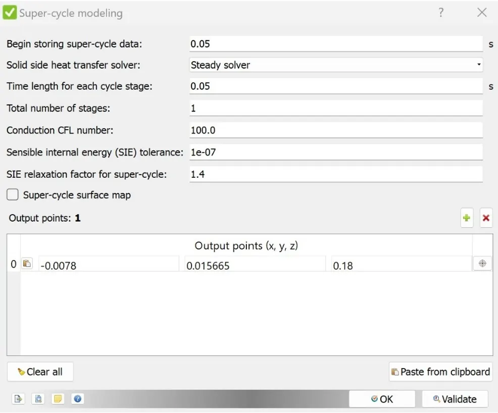
Initially the super cycle stage interval was 0.05. In the later simulations, the super cycle stage interval was changed to 0.01, 0.02 and 0.03.
Grid sizing
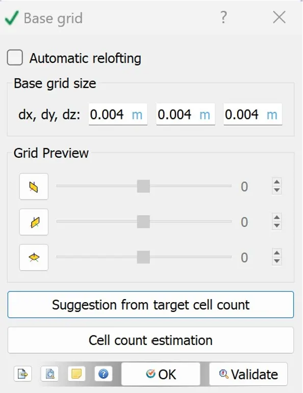
Three base grid sizes were used. Initially, the base grid size was 4 mm. The grid size was changed to 3 mm and 2 mm later for the simulations.
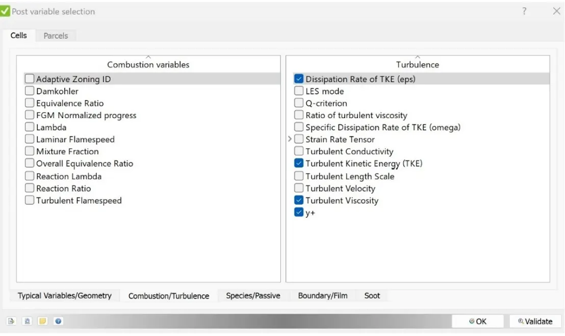
Setting post variable y+
Final validation of case setup
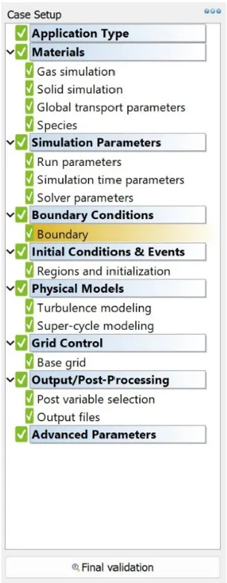
After setting up the case, the final validation showed no errors/warnings.
Running the simulation
The simulations were run on HPC facility with 1 CPU node and 20 processors. Mobaxterm interface was used to access and run the case.
Results and discussion:
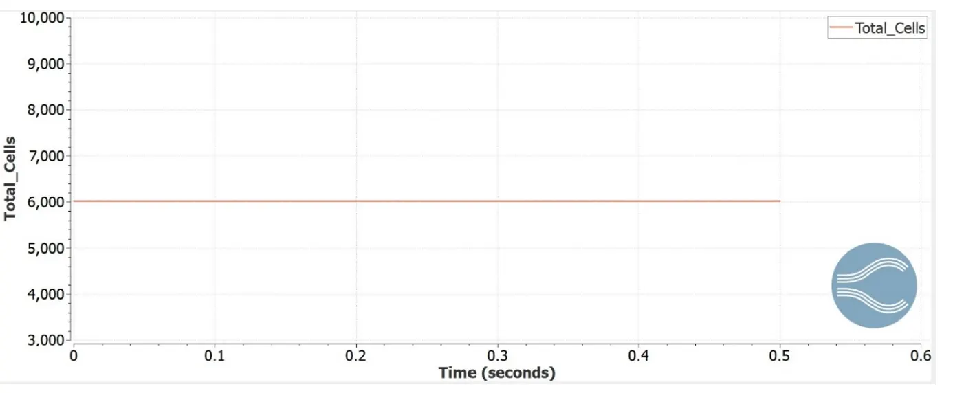
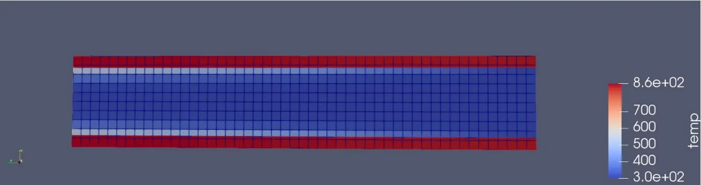
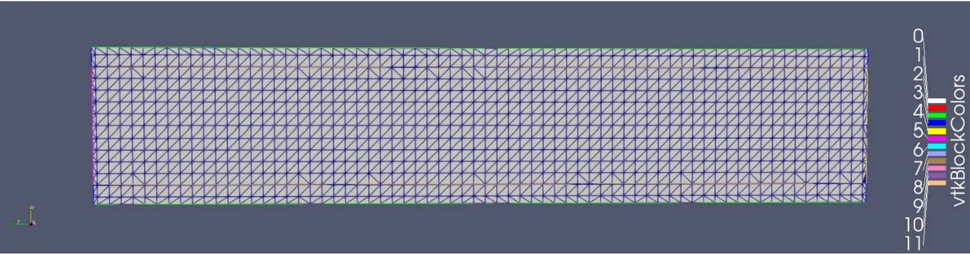
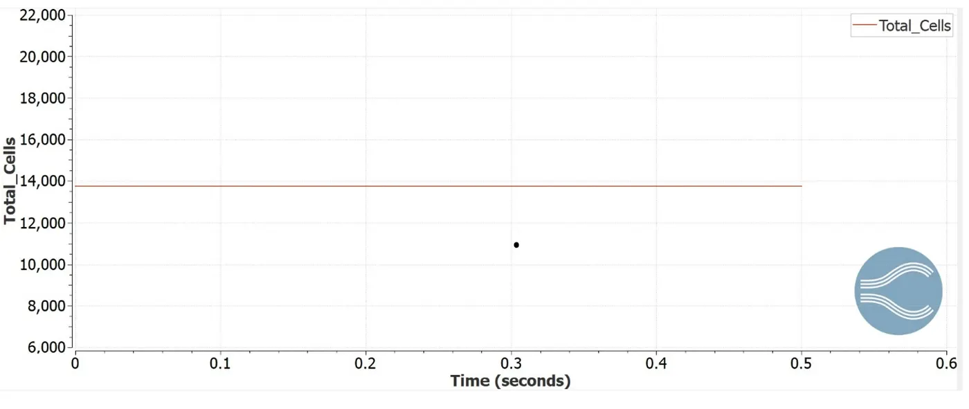
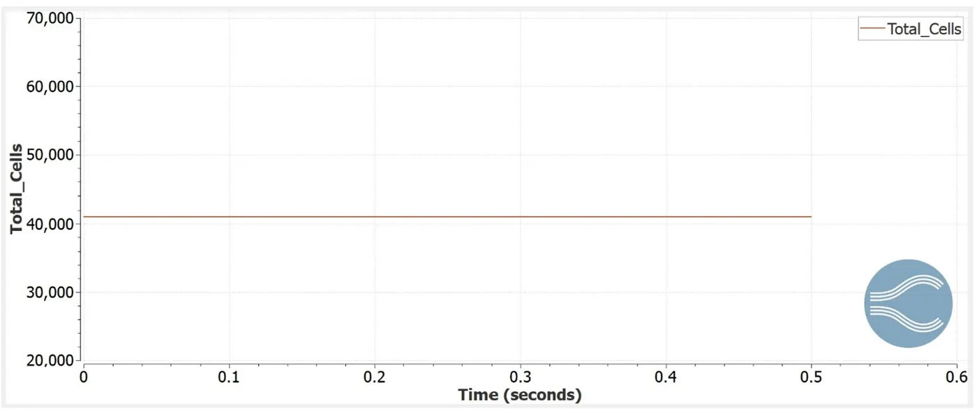
The three different base grid sizes (4mm, 3mm, and 2mm) are compared. The total number of cells during simulation increased with the finer mesh. The total number cells were 6018, 13736, and 41006 with base grid size of size 4mm, 3mm and 2mm, respectively.
Base grid size 4 mm
Total number of cells (4mm)
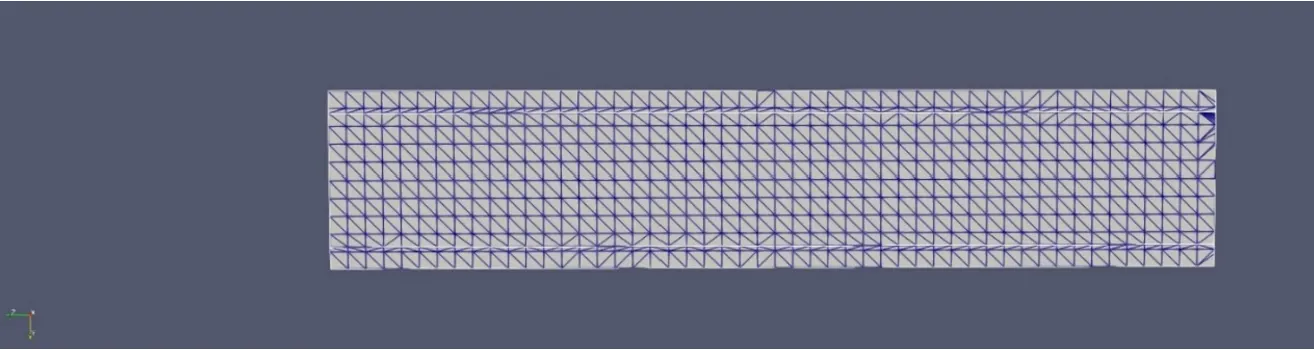
Temperature contour (4 mm)
Base grid size 3 mm
Total number of cells (3mm)
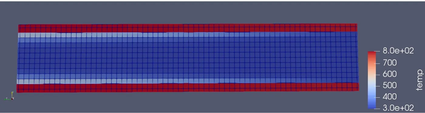
Temperature contour (3 mm)
Base grid size 2 mm
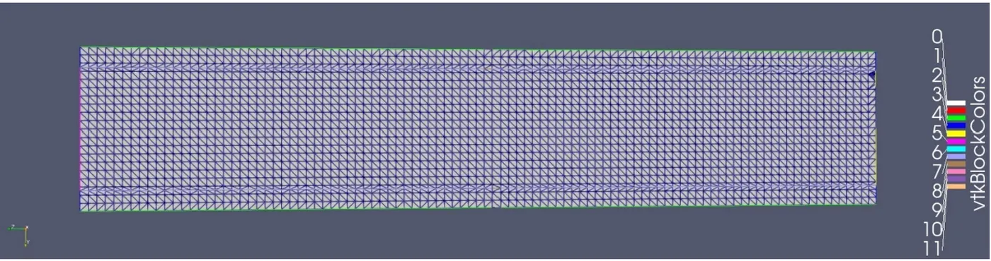
Total number of cells (2 mm)
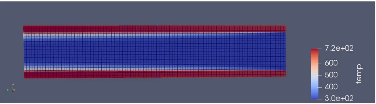
Temperature contour (2 mm)
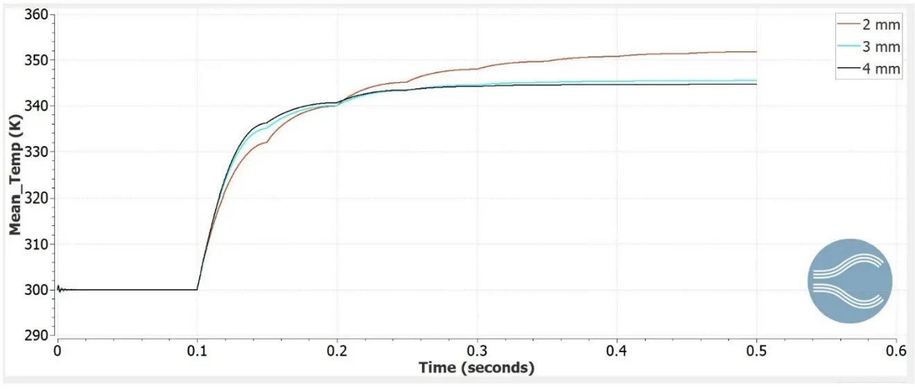
Effect of grid size on Mean temperature of fluid region
Effect of grid size on Mean temperature of solid region
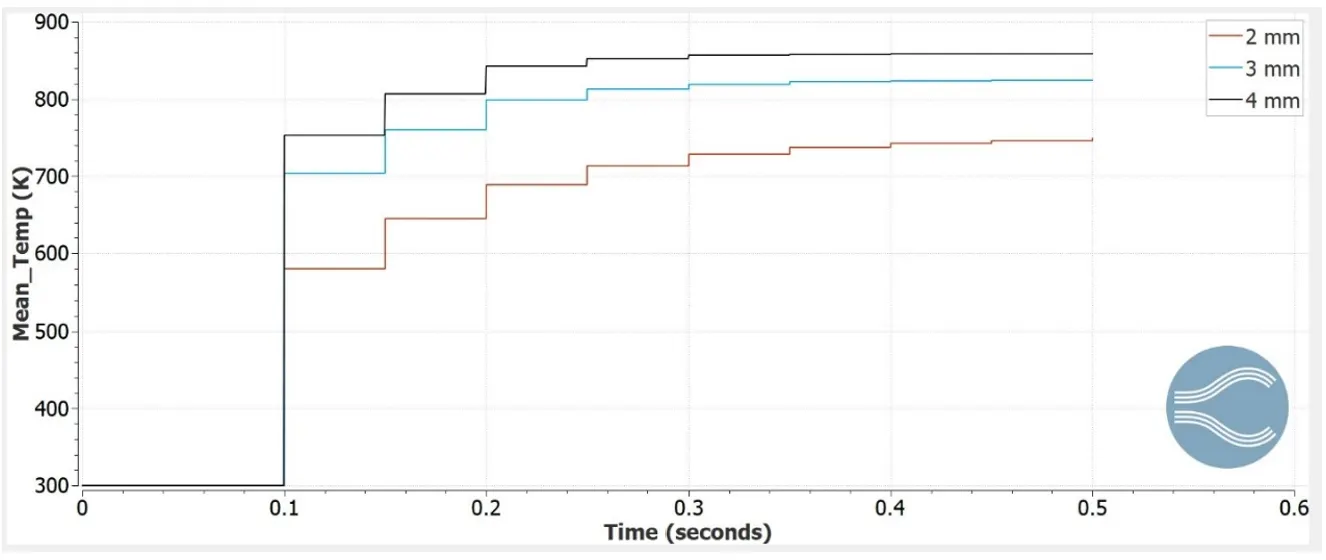
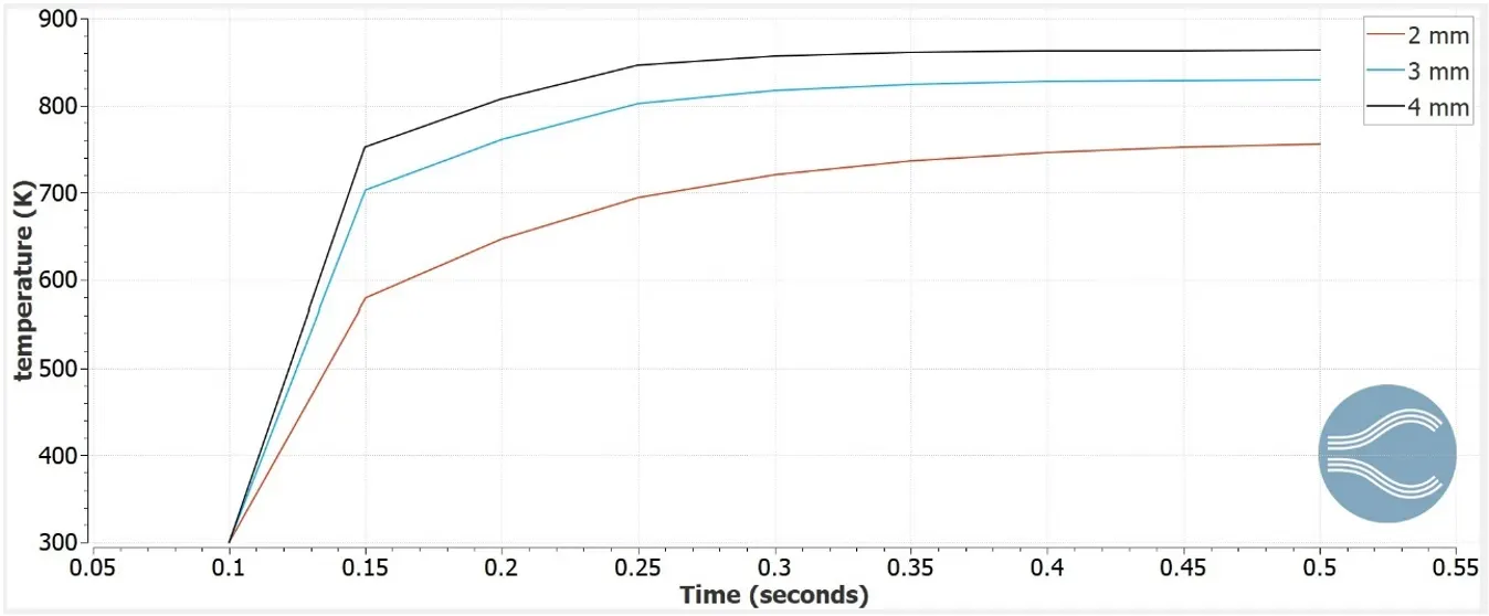
Temperature at monitor point
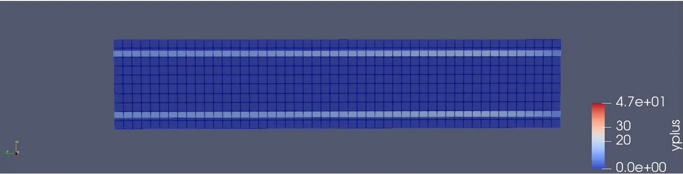
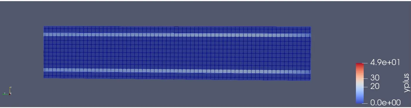
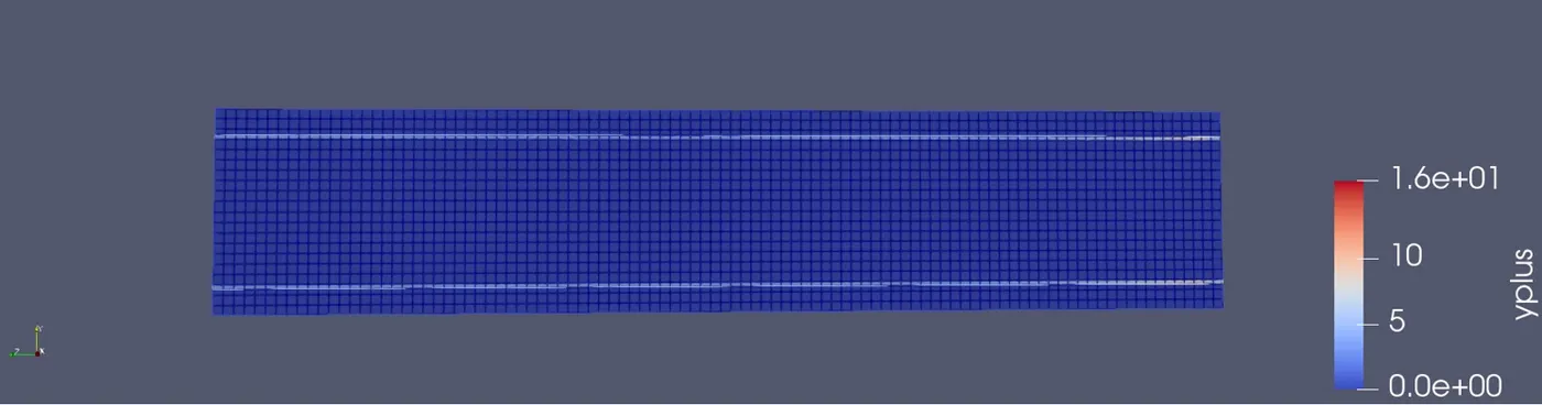
Effect of grid size on Y plus
Grid size Y+
4 mm 47
3 mm 49
2 mm 16
Y plus (base grid size 4mm)
Y plus (base grid size 3mm)
Y plus (base grid size 2mm)
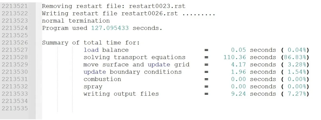
Effect of super cycle stage interval on total simulation time
Total time taken (Base grid size of 4mm and super cycle stage interval of 0.05) – Base configuration
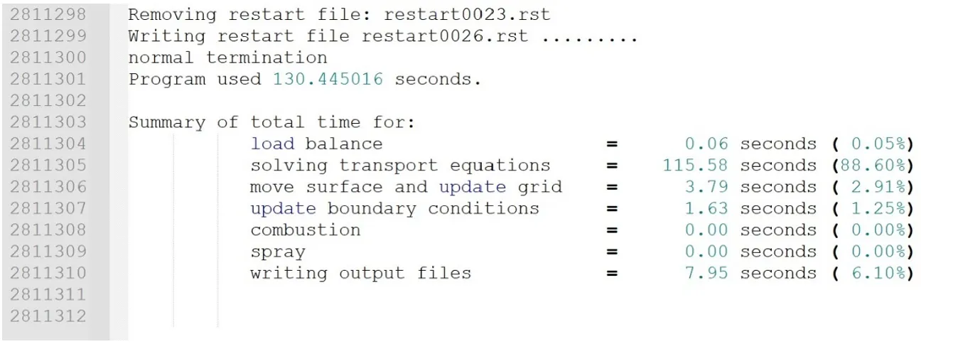
Total time taken (Base grid size of 4mm and super cycle stage interval of 0.01)
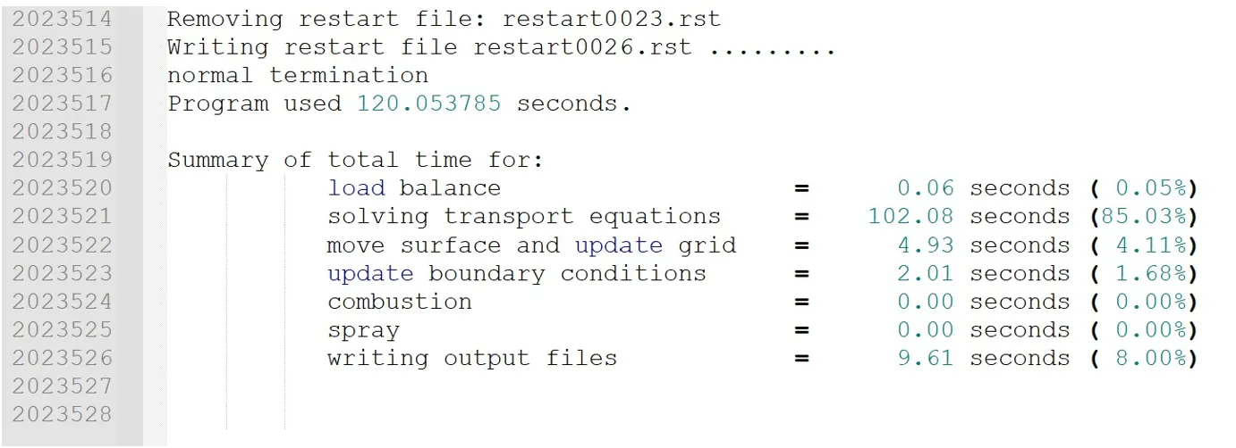
Total time taken (Base grid size of 4mm and super cycle stage interval of 0.02)
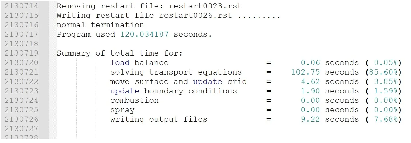
Total time taken (Base grid size of 4mm and super cycle stage interval of 0.03)
Conclusions:
· ◊ The base configuration of case setup includes a base grid size of 4mm, inlet velocity of 5 m/s and super cycle stage interval of 0.05.
· ◊ The total number of cells increased from 6018 to 13736 and 41006 with the increase of base grid size from 4mm to 3mm and 2mm respectively. Thus, refinement of mesh causes increase number of cells.
· ◊ Results show that the mean temperature of fluid and solid region were similar with base grid size of 4 mm and 3mm. However, the mean temperature of fluid was considerably higher and mean temperature of solid was considerably lower compared to results of other base grid sizes. Hence, the results are dependent on base grid size and 2mm grid size gives more accurate results compared to 3mm and 4mm.
· ◊ Temperature at monitor point starts to rise sharply at 0.1s and stabilizes after 0.4s.
· ◊ The value of Y+ was found to be 47, 49 and 16 for the base grid size of 4mm, 3mm and 2mm, respectively. The Y+ values change drastically at 2mm base grid size.
· ◊ There is no considerable effect of super cycle stage interval on simulation time.
Animation videos
Base configuration (Base grid: 4mm, super cycle stage interval: 0.05, inlet velocity: 5 m/s)
· Velocity contour
· Temperature contour
· Pressure contour
https://www.youtube.com/watch?v=8IE5jk2JK4I&ab_channel=AksheyMarwaha
· y+ contour
Base grid: 4mm, super cycle stage interval: 0.05, inlet velocity: 3.7 m/s
· Velocity contour
· Temperature contour
· Pressure contour
· y+ contour
Base grid: 4mm, super cycle stage interval: 0.03, inlet velocity: 3.7 m/s
· Velocity contour
https://www.youtube.com/watch?v=WcuCu-1Ve6U&ab_channel=AksheyMarwaha
· Temperature contour
https://www.youtube.com/watch?v=4EonU8JfHTk&ab_channel=AksheyMarwaha
· Pressure contour
https://www.youtube.com/watch?v=mtETpnXK-mM&ab_channel=AksheyMarwaha
· y+ contour
https://www.youtube.com/watch?v=VbXX3VbOJUc&ab_channel=AksheyMarwaha
Base grid: 4mm, super cycle stage interval: 0.02, inlet velocity: 3.7 m/s
· Velocity contour
https://www.youtube.com/watch?v=yVDNORXi8oI&ab_channel=AksheyMarwaha
· Temperature contour
https://www.youtube.com/watch?v=xv-MnTcXRnc&ab_channel=AksheyMarwaha
· Pressure contour
https://www.youtube.com/watch?v=LSU7mPUt6Eo&ab_channel=AksheyMarwaha
· y+ contour
https://www.youtube.com/watch?v=_kCRGiJ9bjU&ab_channel=AksheyMarwaha
Base grid: 4mm, super cycle stage interval: 0.01, inlet velocity: 3.7 m/s
· Velocity contour
https://www.youtube.com/watch?v=nzCF0wmD8VM&ab_channel=AksheyMarwaha
· Temperature contour
https://www.youtube.com/watch?v=6_s_4er5irA&ab_channel=AksheyMarwaha
· Pressure contour
https://www.youtube.com/watch?v=VA7VoEEHiBs&ab_channel=AksheyMarwaha
· y+ contour
https://www.youtube.com/watch?v=LNk0oy1BqMs&ab_channel=AksheyMarwaha
Base grid: 3mm, super cycle stage interval: 0.05, inlet velocity: 3.7 m/s
· · Velocity contour
https://www.youtube.com/watch?v=p8EbNffWhTQ&ab_channel=AksheyMarwaha
· Temperature contour
https://www.youtube.com/watch?v=cHTI5BHX7Kk&ab_channel=AksheyMarwaha
· Pressure contour
https://www.youtube.com/watch?v=mLj0egFaxis&ab_channel=AksheyMarwaha
· y+ contour
https://www.youtube.com/watch?v=bZ396a8i-EI&ab_channel=AksheyMarwaha
Base grid: 2mm, super cycle stage interval: 0.05, inlet velocity: 3.7 m/s
· · Velocity contour
https://www.youtube.com/watch?v=WTP5x63ImEw&ab_channel=AksheyMarwaha
· Temperature contour
https://www.youtube.com/watch?v=n_ZEXMbfwic&ab_channel=AksheyMarwaha
· Pressure contour
https://www.youtube.com/watch?v=sDOkbPQ9KKQ&ab_channel=AksheyMarwaha
· y+ contour
https://www.youtube.com/watch?v=DOn9VobKrJI&ab_channel=AksheyMarwaha