Week 6:- Clamp Unit & Pin-Clamp Unit Design Challenge
OBJECTIVE:
To design 3 different types of Swivel clamp units with different risers, blades, and clamp arms for the given panel & to design a pin clamp unit for the given car panel.
ABSTRACT:
In this project, I have designed different types of swivel clamp unit by validating a swivel clamp cylinder and by considering a clamping force acts at each end of the mylars for the given car panel. Hereby considering the fundamentals of clamp unit design I have briefly explained about the,
Purpose of Clamp unit:
3-2-1 Principle achieved by clamping. Clamp plans.
Structured design tree.
Materials, surface finish & Heat treatment used in the parts of clamp unit.

SOFTWARE USED:
CATIA V5
DESIGN PROCEDURE:
CLAMP UNIT:
- A clamp unit is a unit designed to clamp/hold the car panel with NC blocks / Mylars / Rest by using a pneumatic cylinder. Clamp arm, finger, rest/backup, L-block, shims, Risers, Pneumatic cylinders are the typical parts of clamp unit.
- Clamping force should be considered while designing a clamp unit.
- Mostly to avoid excess part, to reduce the weight & reduce the cost of the fixture the rest unit is combined with the clamp unit.
- The below figure shows the combination of the clamps & rest unit which have been designed in this project by considering the basic principles of clap & rest unit design.
TYPES OF CLAMP UNIT:
- Power Clamp unit.
- Swivel cylinder clamp unit.
In this project, I have used the Swivel clamp unit to design.
PURPOSE OF CLAMP & REST UNIT:
The purpose of clamping tools is to securely hold the workpiece in position without obstructing the production process. High clamping forces combined with compact dimensions are therefore the most important requirements for a clamping tool. For this reason, clamps are also equipped with mechanical transmission gear units.
(3-2-1principle) archived by clamping & resting:
PRINCIPLE OF FIXTURE DESIGN:
For a fixture designer, the major portion of design time is spent on deciding how to locate the workpiece in the fixture. For any free body, there are a total of 12 degrees of freedom as below,
6 translation degrees of freedom.
- X+
- X-
- Y+
- Y-
- Z+
- Z-
And 6 rotational degree of freedom
- Clockwise around X-axis (CROT – X)
- Anticlockwise around X-axis (ACROT – X)
- Clockwise around the Y-axis (CROT – Y)
- Anticlockwise around Y-axis (ACROT – Y)
- Clockwise around Z-axis (CROT – Z)
- Anticlockwise around Z-axis (ACROT – Z)
We must fix all 12 degrees of freedom in order to locate the workpiece in the fixture. So, 12 degrees of freedom of the workpiece need to be fixed & thus we can achieve zero degrees of freedom for the workpiece.
Now try to understand the 3-2-1 principle of the fixture. The purpose of the fixture is Resting – Stability.
- Locating – W.r.t datum.
- Orienting – W.r.t secondary datum. Clamping
Ensuring above not disturbed.
The best & most cost-effective method of part location is referred to as the 3-2-1 method. Fixtures work on of 3-2-1 principle.
3-2-1 PRINCIPLE
The best & most cost-effective method of part location is referred to as the 3-2-1 method.
minimum: Three locator blocks to establish the part plane. Three locator or supports are placed under the workpiece. Three locators are usually positioned at the primary locating surface. This restricts two axial movements downward & upward and four radial movements. Together, the three locators restrict six degree of freedom.
Round locating pin: A round hold that defines the location in four directions (4-Way) perpendicular to the plane previously established. This restricts four axial movements.
Round locating pin: In a slot that defines two of the direction of another pin (2-way). This restricts two radial movements.
Figure. Showing the 3-2-1 method achieved by clamping & resting
As by the 3-2-1 method, introducing a minimum of 3 clamping & 3 resting blocks will restrict 6 degrees of freedom (DOF) [Two axial movements & four radial movements].
DESIGN TREE:
- Structuring a design tree implies a process where all the assemblies & parts are named in a specific standard. Different customers have a different set of standards to structure a design tree.
- It is an important process that helps us to identify a specific part or assembly as to which project, tool/unit, it belongs to. This helps us to avoid errors during design study, manufacturing, assembly, inspection, etc.
- If the parts or assemblies are not named properly or the design tree is not structured properly, it will create confusion to understand the design & may create major possibilities of making an error.
- The naming of a fixture or a unit or a part gives the information as to which project or zone or assembly do they belong to. It can help us to identify the number of items of the same types or different types that are being used in the assembly. While start designing a fixture, the first unit will be the base unit.
- In the structure tree, all the manufacturing parts should be first and the standard parts should be at the last. Structure tree helps to study or understand the parts in the assemblies easily
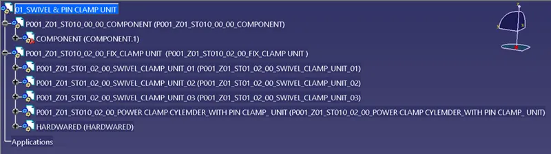
Figure. Design tree for this project
Under each unit will contain parts of the unit as shown in the above figure. PLP LOCATION & CLAMP PLAN:
PLP (PRINCIPLE LOCATING POINTS):
Principle locating points are the points that are used for the accurate location of the panels' sub-assemblies to maintain the geometry of the assembly.
There are lots of holes on the panel which is accurate due to stamping operations. So the PLP is defined in the drawings. The PLP holes must be very much precise.
CLAMP PLAN:
- The clamp plan provides information on the location of pins, rest units, clamp unit, dumps, etc.
- It is the important input from
- The clamp plan/position should not be changed without the knowledge
- It gives the detail of the exact position of the clamping units by mentioning a coordinate in the particular position
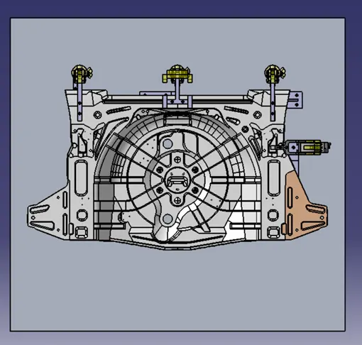
Figure. PLP & CLAMP PLAN
The above figure shows the PLP points & the coordinates of clamps which will be mentioned in the clamp plan given by the customers.
MATERIAL USED:
In general, the materials used for Mylars, Clamp arm, shims, shim block, blades & risers are:
- Mylars: UHMW, Nylon66, PP, Teflon (Poly tetra fluor ethylene (PTFE)). Materials of clamp block and rest block to be decided as per the A class panel or B
- Clamp Arm: SAE 4140 or SAE 1045.
- Shims/spacer: S.A.E. 1010 CRS FULL HARD, COLD ROLLED STRIP STEEL S.A.E. 1010 FULL HARD, S.A.E. 1020 HRS, etc.
- shim block: STEEL ASTM A- 36, NM stainless, STEEL ASTM A-36, SS type 3030 or 304,
- Blade: STEEL ASTM A-36,
- Riser: STEEL ASTM A- 36,
HARDNESS:
In general, the hardness of the materials for pins, pin retainers, shims, shim block, blades & risers are 55 – 60 HRC to a depth of 0.5 -0.7mm after grinding.
SURFACE FINISH:
In general, the hardness of material for Mylars, Clamp arm, shims, shims block, blades & risers are:
- Clamp arm: Munsell No.3.75YR6/14 safety orange
- shims/spacer: BLACK OXIDE FINISH (SURFACE TO BE FLATE PARALLEL TO WITHIN 0.015 T.I.R.
- Riser: SURFACES TO BE FLAT, PARALLEL & PERPENDICULAR TO WITHIN 0.015 T.I.R.
UNIQUE PARTS OF A CLAMP & REST UNIT:
Finger: The finger is an NC block, which is mounted on the clamp arm of the cylinder. And will press the car panel towards the rest, so it holds the car panel.
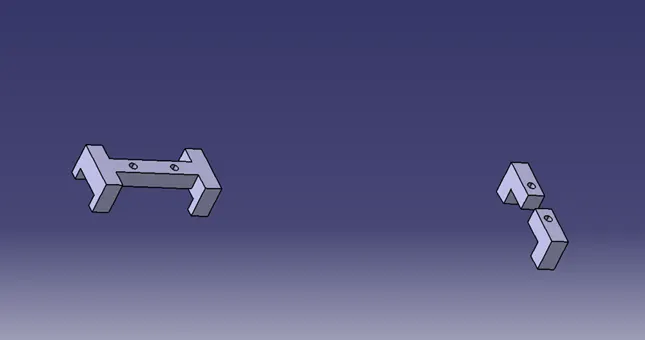
Figure. Clamping Mylar / Finger used in this projects
REST: A rest is an NC block, which is fixed to the unit to support the car panel, Also it resists the clamping force of the finger & thus clamp the car panel.
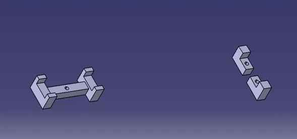
Figure. Resting mylar/rest
CLAMP ARM: The clamp arm is a part to which all the moveable parts are fixed. In general, clamp arms are available based on the position of the arm. Clamp arm made from hard material.
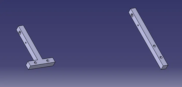
Figure. Clamp Arm
STOPPER: The function of the stopper is to restrict clamps going beyond the limit. The stopper is mounted between the clamp arm and the rest or blade. The stopper has two parts, when these two parts meet they restrict motion.
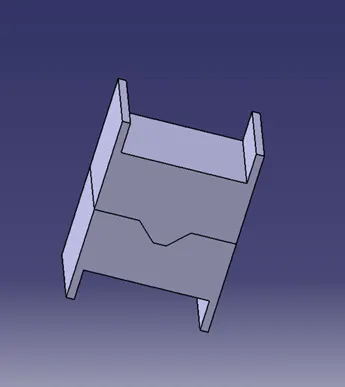
Figure. Stopper
Blade: Blades are required for both the open clevis style clamps and power clamps. A blade allows the NC locator to be mounted or machined at a specific datum location.
Depending on the clamp style, the blade must accept either a locating component or have the locating surface machined into the detail.
All Blades shall have tapped holes for mounting to the riser. The hole pattern must match the NAAMS pattern to accommodate NAAMS risers or unique design weldments. The riser shall have clearance holes that allow the hex head fasteners to secure the blade to the riser. Maximum load figures are based on a maximum bracket deflection of 0.13mm.
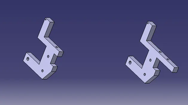
Figure. Blade
RISER: Riser is a standard part or makes a part, which provides height to the pin unit, clamp unit as per requirements. The riser should have adequate so it can sustain under a load of car panel, clamping cylinder, and other parts. All the following parts are mounted on the riser they are, Mylars, rest Mylars, Blade, Cylinders, and Clamp arm.
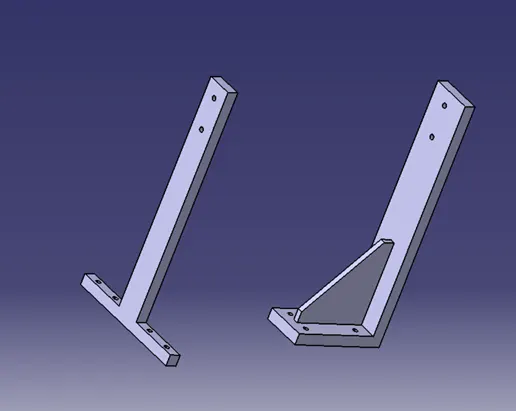
Figure. Riser
CLAMPING CYLINDER:
CKG1B63-100YAZ-P4DWSC-XC88 (0 0) - SMC Cylinder
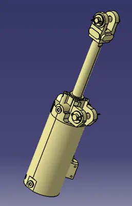
Figure . Cylinder (CKG1B63-100YAZ-P4DWSC-XC88 (0 0))
Swivel Clamps :
The primary components of the clevis clamp include clamp arm, blade, cylinder, angle riser, locator block, and finger. Swivel clamps shall typically be designed with the center of the clamp cylinder, the center of the locator, and the center of the clamp arm on a common line. However, it is acceptable to offset the clamp point from the clamp cylinder to allow for improved access for welding and part load and unload.
The clamp arm shall be welded construction including a 20.0mm thick arm with an integral pivot to accommodate a 19.50mm wide Swivel. The female portion of the clevis shall always be part of the arm. The male portion of the Swivel shall always be part of the blade.
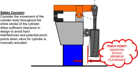
Figure. Safety Concern
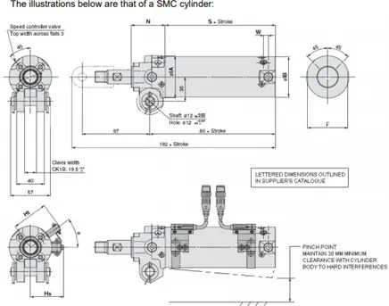
Figure. 2D of clamping Cylinder Clevis Clamp Applications:
Improved Weld Access – Swivel clamps allow for increased part and weld density within each tool. This can enable a reduction in the overall quantity of tools. Less Weight – In certain applications, (geo-pallets, moving mass applications,
- vertical slides, and end effectors), the weight of the tool is high The typical open Swivel unit weighs less than the typical power clamp unit.
Clamp Calculation:
63mm Bore Cylinder Force Calculation:
F1 (63mm Bore Cylinder) = r 2 (5.5 bar) = (3.14) x (31.5mm)2 x (5.5bar)
= (3.14) x (31.5mm)2 x (550,000 Pa)
F1 = (3.14) x (31.5mm)2 x (1m/1000mm)2 x (550,000Pa) F1 = (3.14) x (545.74 N)
F1 = 1714 N = (386 lbs ) = Actuating Force of Cylinder
Now that F1 is calculated, (1714 N), and knowing that the Clamping Force, F2, must have a minimum clamping force value of 445N (100lbf)
Then F1 / F2 = 1714 N / 445 N = 3.8 (Force Ratio)
The Force Ratio of (3.8) can be used for 63mm bore cylinders to calculate the relationship between the distance from cylinder Swivel to clamp arm pivot, L1, and the distance from clamp arm pivot to the center of pressure foot/locator, L2. The Force Ratio to guarantee a minimum of 445N of clamping force for a 63mm bore cylinder is shown below:
Then
L2 ≤ F1L1/ F2 & L2 ≤ 3.8 L1
The table shown below illustrates the acceptable distances from the clamp arm pivot to the center of the pressure foot, L2, when the distance between the cylinder clevis to the clamp arm pivot, L1, is given to be 100mm.
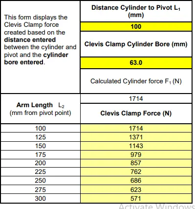
Figure. Swivel clamping force
IMAGE OF FIXTURE:
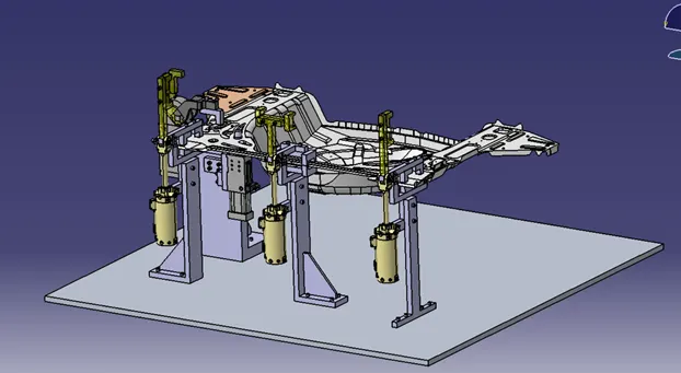
Figure. Panel with All Element
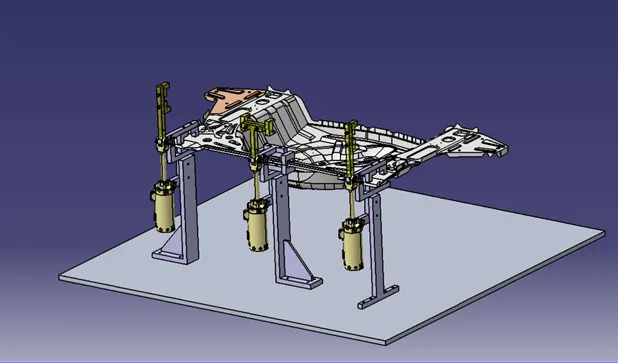
Figure. Panel with Swivel cylinder clamp unit
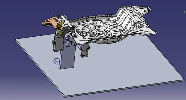
Figure. Panel with Pin clamp unit
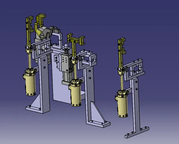
Figure. Swivel cylinder & Pin clamp unit without panel
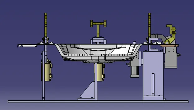
Figure. Front View
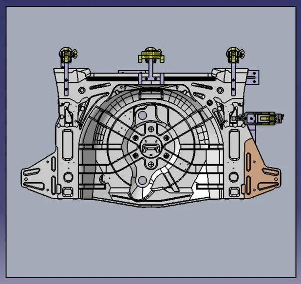
Figure. Top View
CONCLUSION:
Hence as per objective, the 3 different types of Swivel clamp unit and by considering a clamping forces acts at each end of the mylars & pin unit clamp has been designed. Also, the materials, surface finish & heat treatment used in the parts of clamp unit, the purpose of clamp unit, (3-2-1principle) achieved by clamping, PLP points (Principle Locating Points) & Clamp plans are briefly explained in detail.