Week 6 - CHT Analysis on a Graphics card
Problem Statement:
To Perform a steady-state conjugate heat transfer analysis on a model of a graphics card.
- Run the simulation by varying the velocity from 1m/sec to 5m/sec for at least 3 velocities and discuss the results.
- Find out the maximum temperature and heat transfer coefficient attained by the processor.
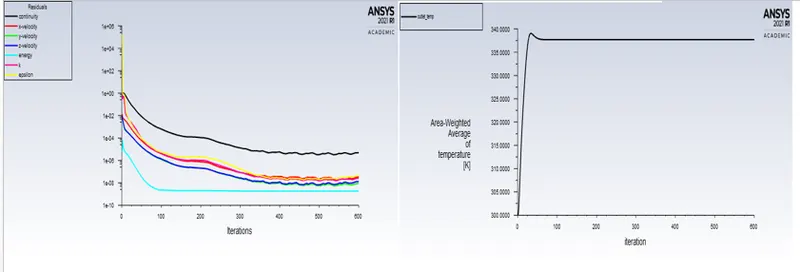
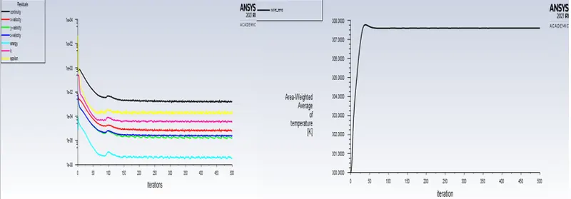
- Prove that the simulation has achieved convergence with appropriate images and plots.
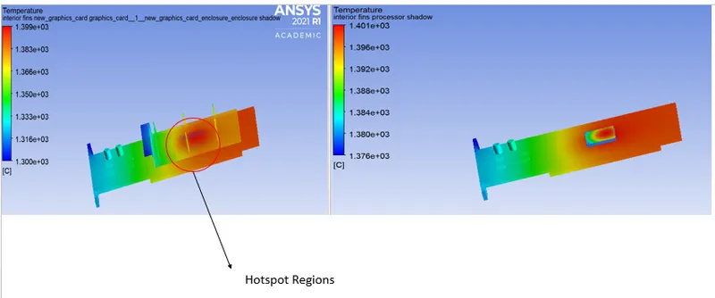
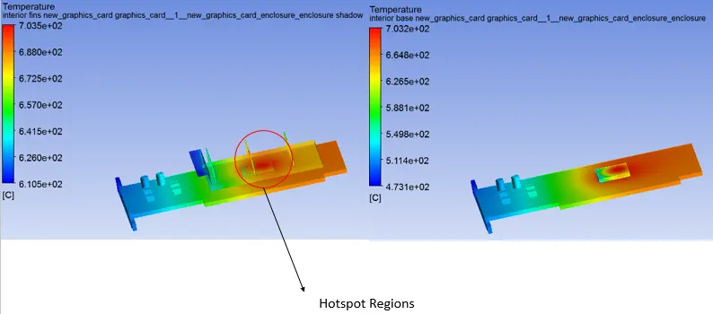
- Identify potential hotspots on the model.
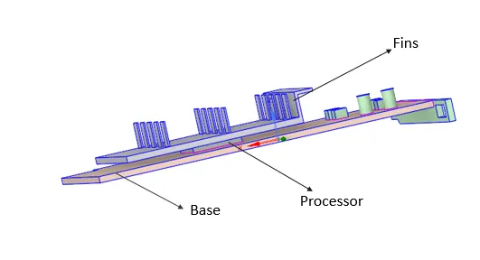
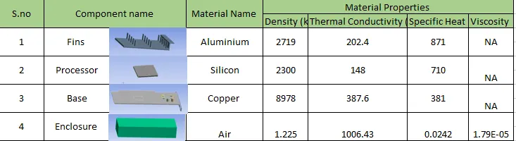
Material Properties :
Assuming power consumption by the processor is 85 W
Volume of the processor : 64 mm^3
Heat Generation rate by the processor would be :1328125000 w/m^3
Case : Baseline Mesh
Element Size: 10 mm
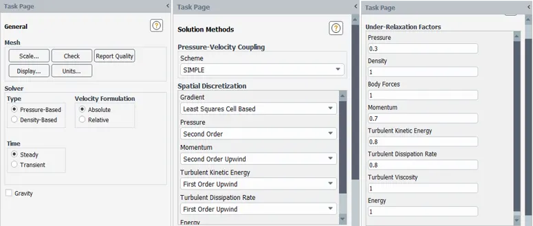
Solver Settings:
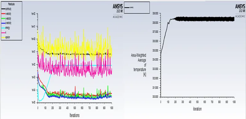
Convergence Plots:
Contour plots :
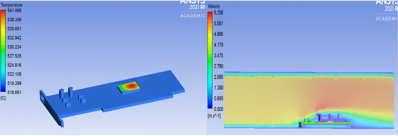
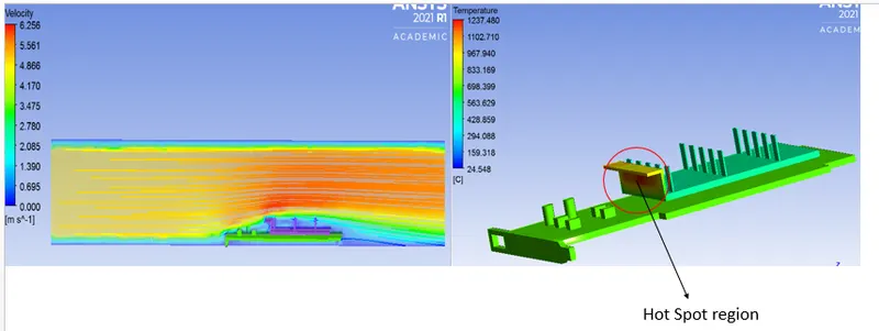
Maximum Temperature attained by processor is 541.068 deg C
Case 1 : Velocity :1 m/s
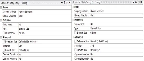
Refined Mesh
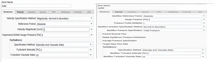
Boundary Conditions:
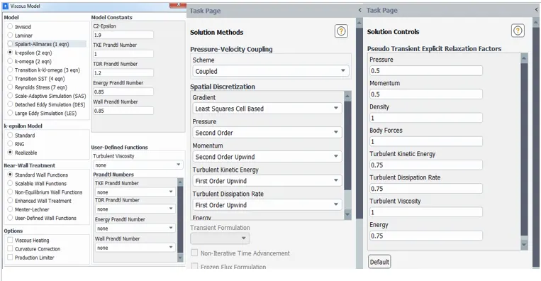
Solver Settings:
Convergence Plots:
Case 2 : Velocity :3 m/s
Convergence Plots: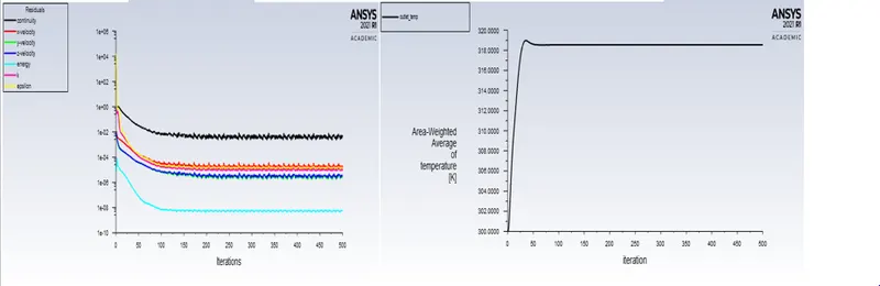
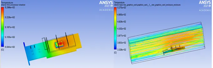
Contour plots:
Case 3 : Velocity : 5m/s
Convergence Plots:
Contour plots:
To calculate the heat transfer coefficient attained by the processor,Following method has been adopted as
mentioned below:
Q=hA(T2-T1)
where,
T1=Temperature of the surrounding fluid,
T2=Temperature of the solid surface,
Area=160 mm^2

Conclusion :
With reference to above data, it can be said that as the velocity increases, the temperature decreases and vice -versa ,tendency to transfer heat increases..