Week 6 - CHT Analysis on a Graphics card
GRAPHICS CARD
Every graphics card has a GPU, which is the heart of the Graphics card. It is the primary component of the graphics card that handles the mathematical computations needed to create visuals. Usually, it is placed underneath a fan or heat sink because when performing calculations, the processor can get extremely hot. Some of the GPU processors provide advanced functionalities, such as offering 3D graphics that look smoother through full-scene anti-aliasing.
What are the components of a graphics card made of? What is the significance of the material?
- Memory
- Internal Interface
- DVI / HDMI / VGA Ports
Different Types of Graphic Cards
- On-Board.
- PCI Express.
- Accelerated Graphics Port (AGP)
- External Graphics Cards.
- Legacy Graphics Cards
GPUs are silicon layered with tantalum and palladium transistors and capacitors for better storage on a smaller chip, which is perhaps the most interesting of the materials used for GPU and RAM cards. These are made from a mind-boggling array of chemicals and copper, boron, cobalt, and tungsten, for starters.
How does heat get generated in a graphics card?
The GPU hardware poses resistance when electricity runs through the chips and circuits in the processor. This resistance generates heat. If you are using a personal desktop computer or a laptop, be it for gaming or other graphics-intensive tasks, the usual temperature range is 149°F to 185°F (65°C to 85°C). The ideal GPU temperature is below 176°F (80°C).
How do you define SHTC in fluent?
The surface heat transfer coefficient is used to determine the rate of convective heat transfer to or from the surface of an item. Convective heat transfer is a method of transferring energy between a solid surface and a moving fluid that uses the combined effects of conduction and fluid motion.
What are cell zone conditions?
Cell zone conditions are where you set options related to the volume/zones. For simpler models, you probably never have to touch these. But if you have multiple volumes with different materials and slightly different models in each (i.e. solid regions and fluid regions) then this is where you would set them.
What is the shadow wall?
It's on the "other side" of the wall. Its primary purpose is to give us a separate label for each side of the wall. It might be smooth on one side and rough on the other (turbulence/wall shear), or it could be white on one side and black on the other (turbulence/wall shear) (radiation). If the thin wall has a limited thickness, you may utilize it to map the temperature on either side.
What is the purpose of shared topology?
The only way to build a conformal mesh where bodies meet is through shared topology, and it is the only way to verify that the intersection of bodies appropriately meshes. The term "shared topology" also refers to volume and surface bodies that are completely contained within another volume or surface body. This is a common occurrence in fluid flow analysis.
What are the types of convection?
There are two types of convection, and they are:
- Natural convection
- Forced convection
Natural convection: When convection takes place due to buoyant force as there is a difference in densities caused by the difference in temperatures it is known as natural convection.
- Examples of natural convection are oceanic winds.
Forced convection: When external sources such as fans and pumps are used for creating induced convection, it is known as forced convection.
Examples of forced convection are using water heaters or geysers for instant heating of water and using a fan on a hot summer day.
What are the convection Boundary condition and their purpose in this study?
A convection boundary condition occurs when the surface is exposed to convective heat transfer governed by Newton's law of cooling. The convective heat transfer coefficient and the free stream temperature could, in general, both be functions of time and position.
How is the source calculated?
When modeling a source term with a UDF, it is critical to understand the context in which the function is invoked. When you add a source term, ANSYS FLUENT will invoke your function while running a global loop on cells. The source term should be computed and returned to the solver by your function.
In this example, a momentum source will be added to a 2D Cartesian duct flow. The duct is 4 m long and 2 m wide and will be modeled using a symmetry boundary through the middle. Liquid metal enters the vent at the left with a velocity of 1 m/s at a temperature of 290 K. After the metal has traveled 0.5 m along the chimney, it is exposed to a cooling wall, which is held at a constant temperature of 280 K. To simulate the freezing of the metal, a momentum source is applied to the metal as soon as its temperature falls below 288 K. The momentum source is proportional to the component of the velocity, vx, and has the opposite sign:
Sx= -CVx
How does the y+ value affect the solution?
This means we are not properly resolving the velocity profile in the viscous sub-layer. In some cases, this can be critical. So try to at least put 3-5 points in the viscous sub-layer. The velocity profile for K-epsilon with a Realizable model with fewer nodes in viscous sublayer. This will not resolve the sub-layer properly and you will be able to get the negative values of velocity in the boundary layer.
Which component has the maximum temperature? Why?
The maximum temperature attained by the graphic is the Processor. When a system runs several applications that may be used for different purposes then the processor gets heated up randomly. If this heat is not controlled by the fan, the other components get heated up as well and get spoil the computer.
Can there be structural displacement due to thermal effects? Can this be calculated using this CHT analysis?
Thermal expansion is an important consideration for engineering because different materials exhibit changes in size when exposed to heat. Thus, affecting length, width, surface area, and volume, etc. The most fundamental relationship that governs the behavior of structures when subjected to thermal effects is ε total =ε thermal +ε mechanical.
Which non-dimensional number is used to compare the conduction-convection in a fluid flow analysis?
In thermal fluid dynamics, the Nusselt number (Nu, after Wilhelm Nusselt) is the ratio of convective to conductive heat transfer at a boundary in a fluid.
Model Approach
Geometry
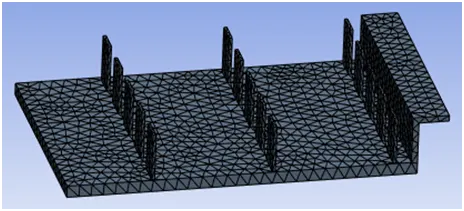
Graphic card is the primary component that handles the mathematical computations needed to create visuals. This is modeled in any 3D software like Solid Edge, Solid works, Catia, ANSA, etc. In the Ansys workbench fluent flow is opened, then editing the geometry in space claim the model is brought into the space claim. Graphic card mainly has 3 components Base, Processor, and fin base. The model is closed with the enclosure.
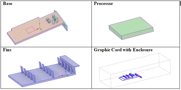
These are made up of the materials like steel, aluminum & copper and their properties are given below
|
Properties/Components |
BASE |
PROCESSOR |
FIN Base |
|
Steel |
Copper |
Aluminium |
|
|
Density [kg/m3] |
8030 |
8978 |
2719 |
|
Specific heat at Constant Pressure Cp [J/kg-K] |
502.48 |
381 |
871 |
|
Thermal Conductivity [W/m-K] |
16.27 |
387.6 |
202.4 |
|
Electrical conductivity [S/m] |
8330000 |
5.8e+07 |
3.541e+07 |
|
Youngs Modulus [Pa] |
2.09e+11 |
1.17e+11 |
7e+10 |
|
Possions Ratio |
0.3 |
0.33 |
0.32 |
The CPU is positioned between the base and the fins, as indicated above. When the CPU is used, heat is produced. The base serves to support the entire assembly. The fins conduct the heat generated by the CPU, cooling it. The fins are cooled by air and air at room temperature (25 degrees Celsius) passes over the graphic card assembly, transporting heat away via convection. The fins increase the accessible surface area for convection.
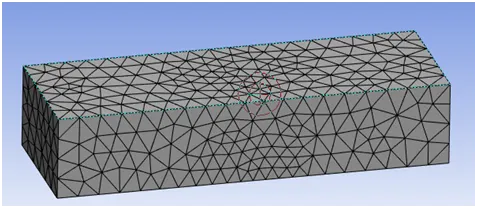
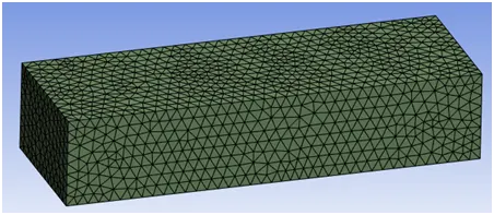
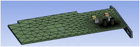
MESH
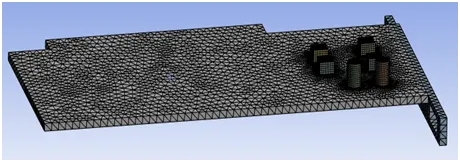
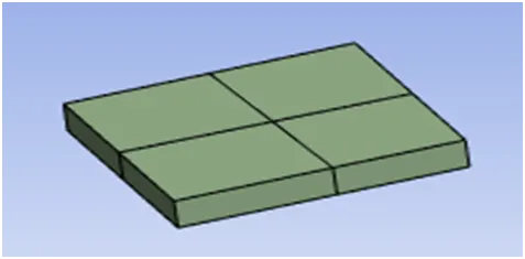
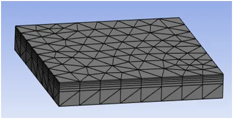
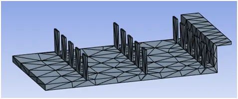
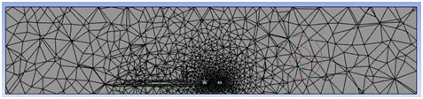
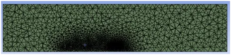
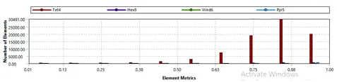
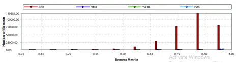
For the given geometry the default mesh is generated then by seeing the default mesh we can refine the mesh wherever required. In our geometry, after obtaining the default mesh the enclosure mesh is enough to run the analysis but for the graphic card wherever the heat is generated that part has to be refined for the analysis. Those parts are the base, processor, and fin. For the base and fin, the mesh size is reduced to 1mm and for the processor, the mesh size is reduced to 0.5mm.
|
Default Mesh |
Refined Mesh |
 |
 |
 |
 |
 |
 |
 |
 |
 |
 |
 |
 |
Pre Post Approach
Setup
Reynolds number
Since Reynolds Number is above 4000, the turbulent model chosen is K-Ɛ for solving the equation.
There is conduction that happens between the components from the processor to the fins and base heat flux is calculated for the processor material where heat is generated. Here for our analysis copper material is used for the processor.
Heat Flux is obtained from the Fourier law
q= Heat Flux [W/m2]
k= Thermal Conductivity of a Material [W/m-K]
A= Area of processor [m2], ∇T =Temperature Difference [K]
Heat Transfer coefficient
The heat produced by the processor is provided by:
W= Source [W/ m3]
P = Power [W]
Vp = Volume of the Processor [m3]
Nusselt Number is a dimensionless number and is given by the ratio of Convective to Conductive heat transfer at a boundary in a fluid.
|
Boundary Conditions |
Factors |
|
Solver |
Steady-state |
|
Turbulence |
K-Ɛ, Realizable, std wall fn |
|
Energy |
ON |
|
Materials |
Fluid Air, Solid Fin-Aluminium, Processor-Copper, Base-Steel |
|
Heat Produced |
156250000 W/m3 |
|
Inlet velocity |
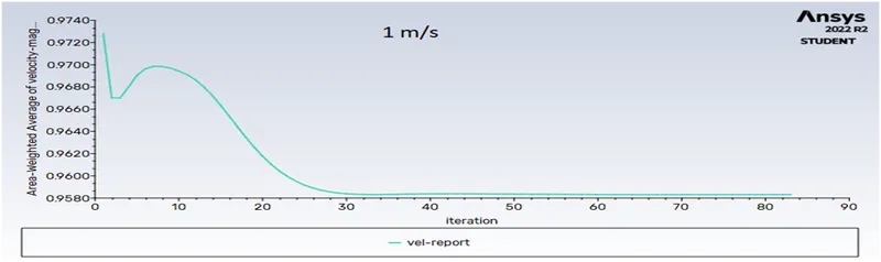
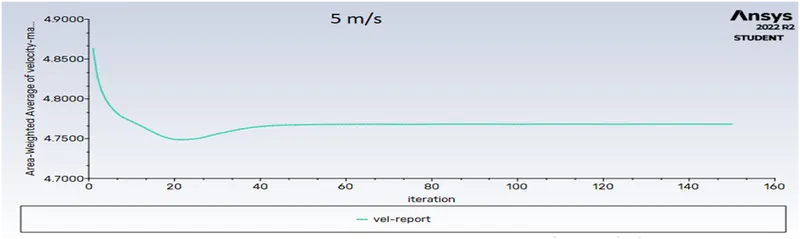
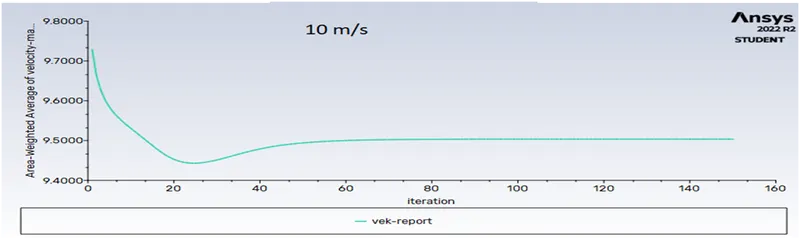
1m/s, 5m/s & 10 m/s |
|
Outlet |
1 atm |
|
Solution Method |
Coupled |
|
Processor Area |
8mm*8mm*1mm |
Post Process Approach
Default Mesh (5m/s)
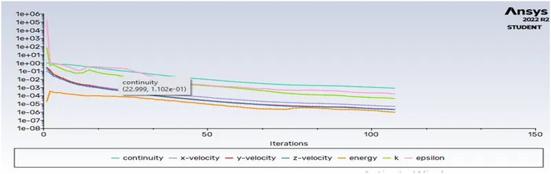
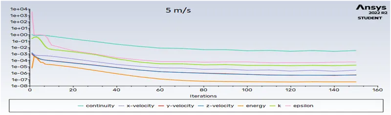
Residuals: The solution converged at 107 iterations.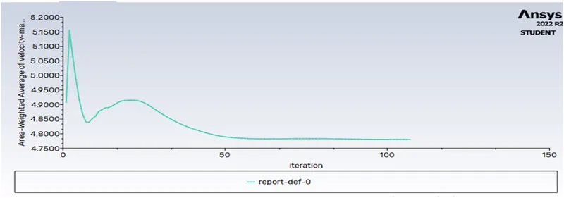
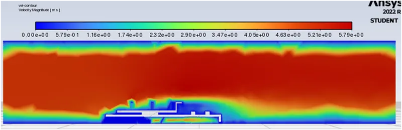
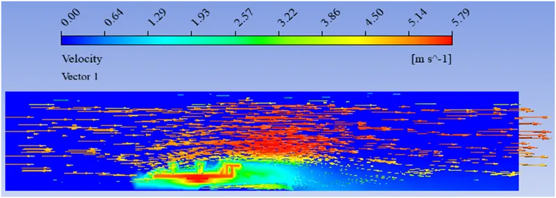
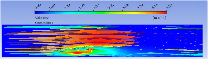
Velocity Magnitude
The Average Velocity can be seen at 4.78m/s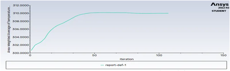
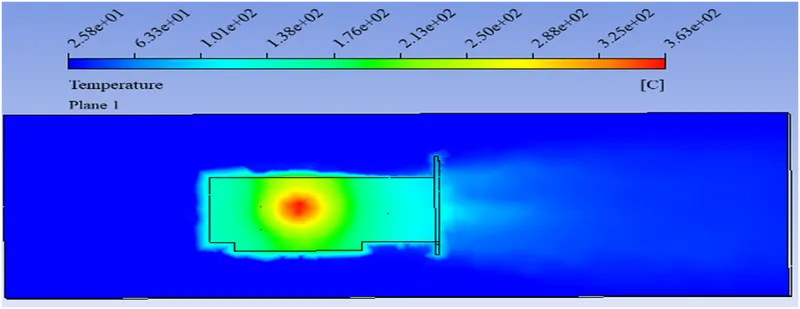
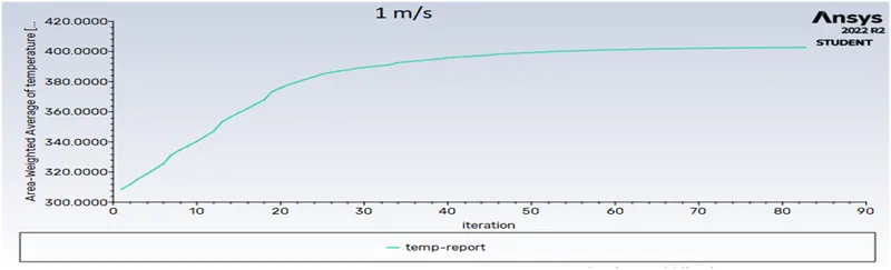
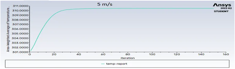
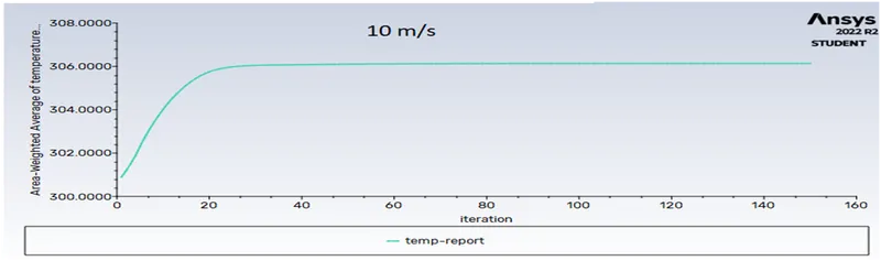
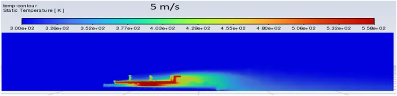
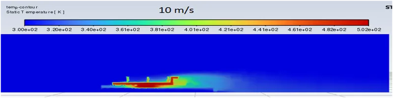
Temperature Magnitude: The Average Temperature can be seen at 310 K or 370 C
Temperature plot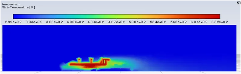
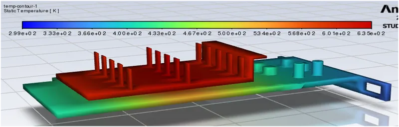
The Maximum Temperature can be seen at 634.3-299= 335.3 K or 62.30 C
Velocity plot
Temperature on plane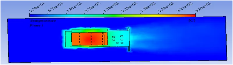
Velocity vectors on the plane
Streamlines
Refined Mesh
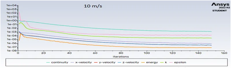
Residuals: 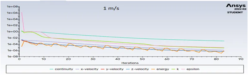
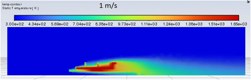
Temperature Magnitude
Velocity Magnitude
Velocity plot
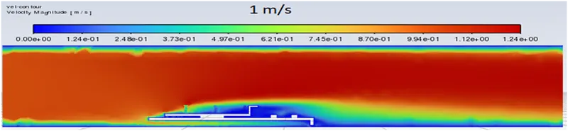
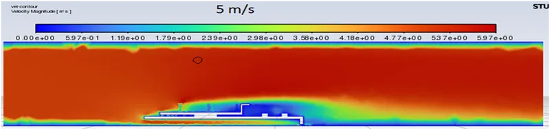
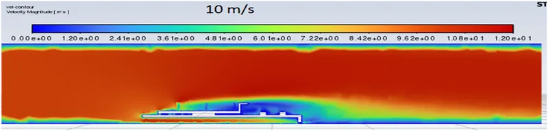
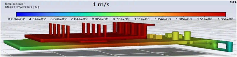
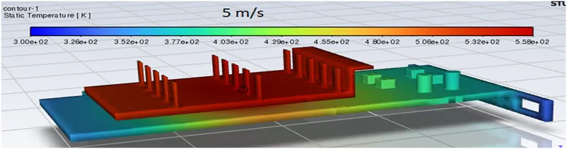
Temperature plot:
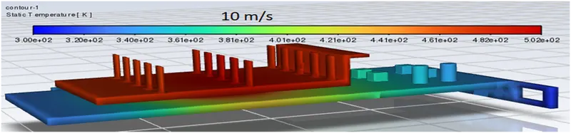
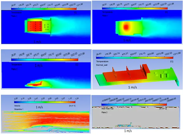
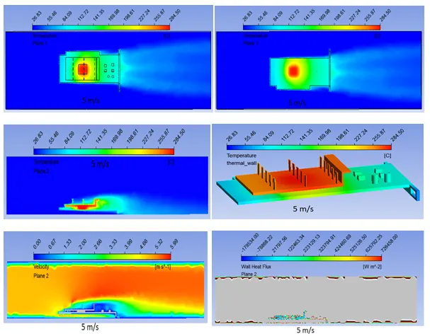
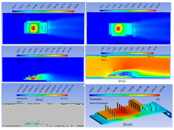
Conclusion:
- The above analysis shows that conjugate heat transfer results in heat distribution in distinct components.
- It was observed that mesh refinement produces more realistic outcomes.
- It was observed that temperature swings in various sections connected to the heat source, such as processors.
- The temperature changes as air go through and the effect of cooling. Convection causes enhanced heat transport.
- The most heat transfer was found at the top of the fins due to direct contact with the processor, and the lowest heat transfer found was d at the recirculation area due to low air velocity.
- Hence, CHT analysis aids in identifying hotspots and other coefficients that may be used to improve device efficiency and performance.