Week 6 - CHT Analysis on a Graphics card
CHT Analysis on a Graphics card
AIM:
Perform a steady-state conjugate heat transfer analysis on a model of a graphics card.
Objectives:
- Run the simulation by varying the velocity from 1m/sec to 5m/sec for at least 3 velocities and discuss the results.
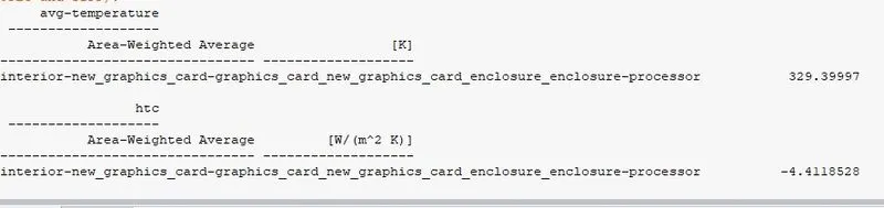
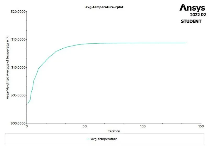
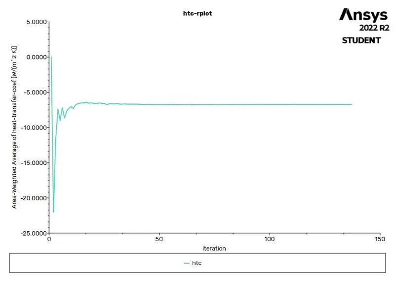
- Find out the maximum temperature and heat transfer coefficient attained by the processor.
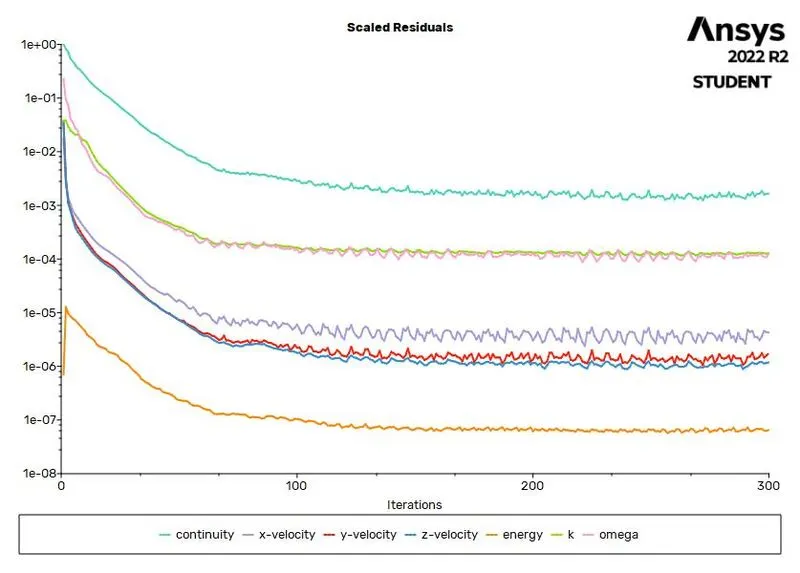
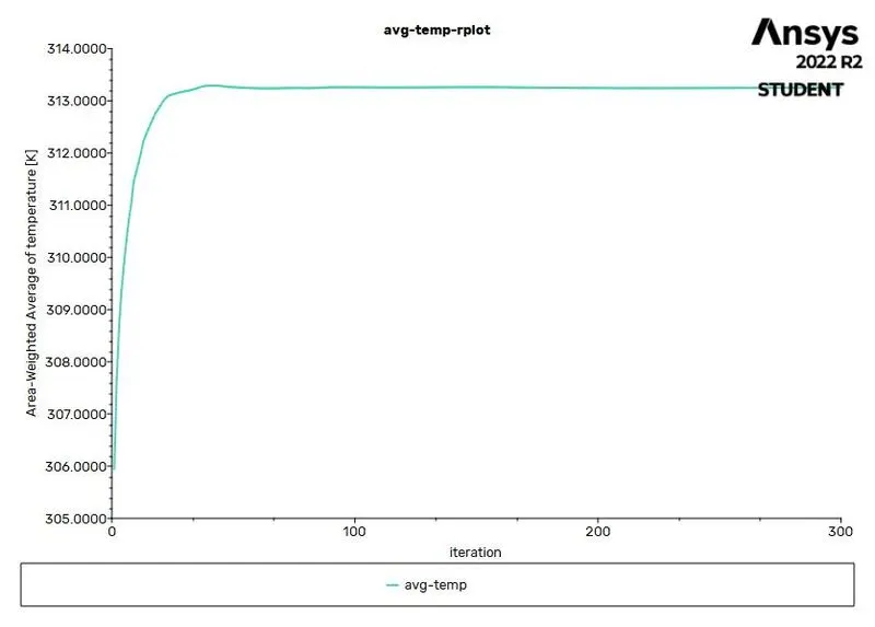
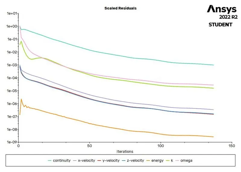
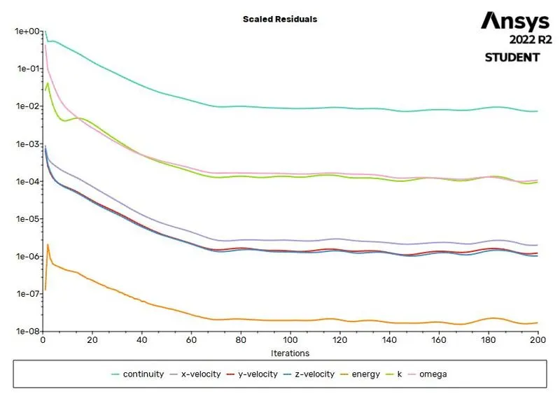
- Prove that the simulation has achieved convergence with appropriate images and plots.
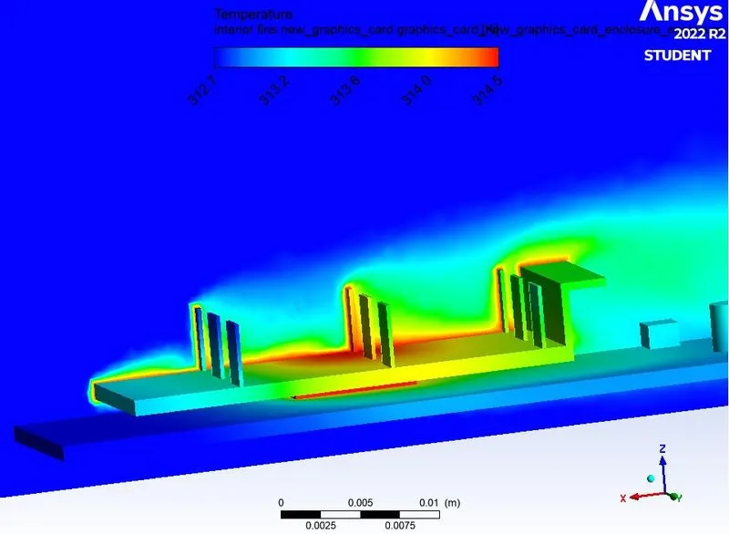
- Identify potential hotspots on the model.
Explanation
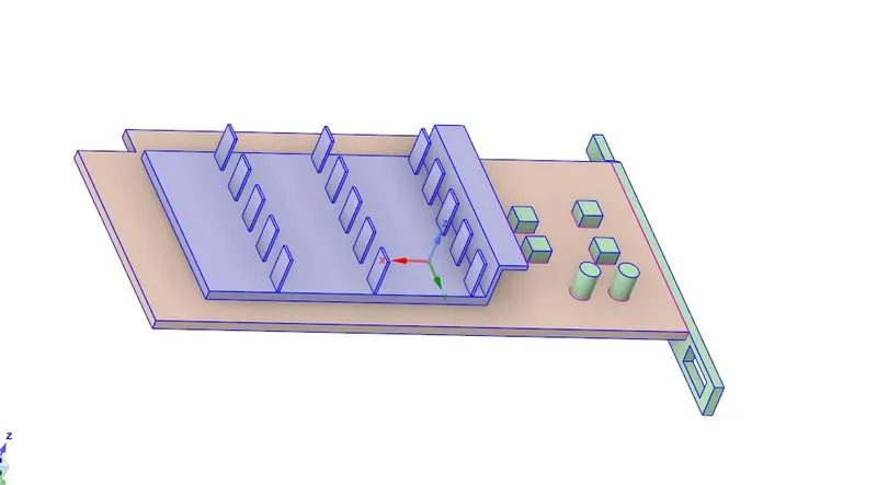
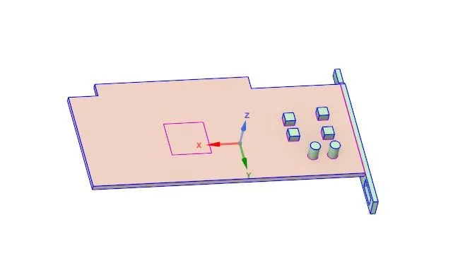
Spaceclaim geometry
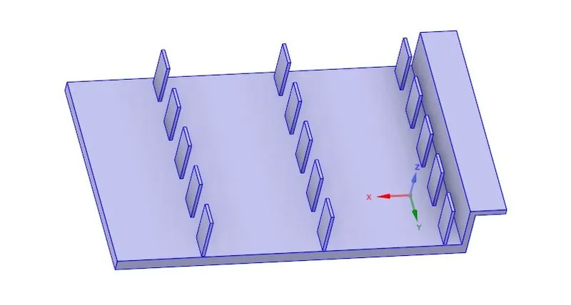
Fins
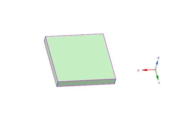
Processor
Base
Meshing
We are going to perform grid independent study with different cases from coarse mesh to finer mesh.
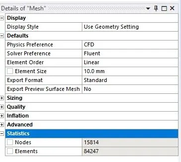
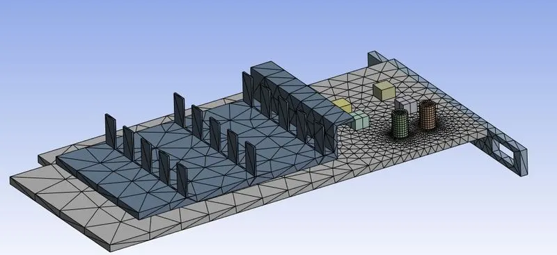
Coarse mesh setup
Here i created coarse mesh of 10mm and the total elements are 84247 and named the corresponding components by named selection.
Setup:
In setup i'm going to assign the materials for corresponding components, creating boundaries and model selections.
For this case i have enabled energy because we are going to deal with heat transfer and K-omega viscous model
Material creation:
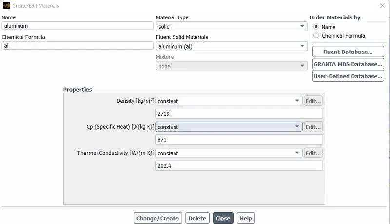
By using fluent database we can create new materials
Fins-Aluminium
Mostly fin materials are having high thermal conductivity like aluminium,copper in most of the applications aluminium is used for heat sinks.
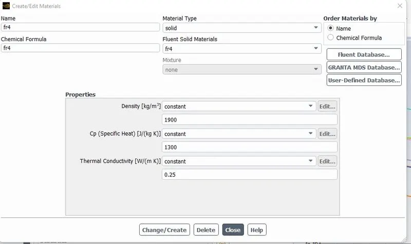
Pcb-FR4
FR4 is widely used in standard boards and applicable in high density uses. FR4 is also very good insulator.
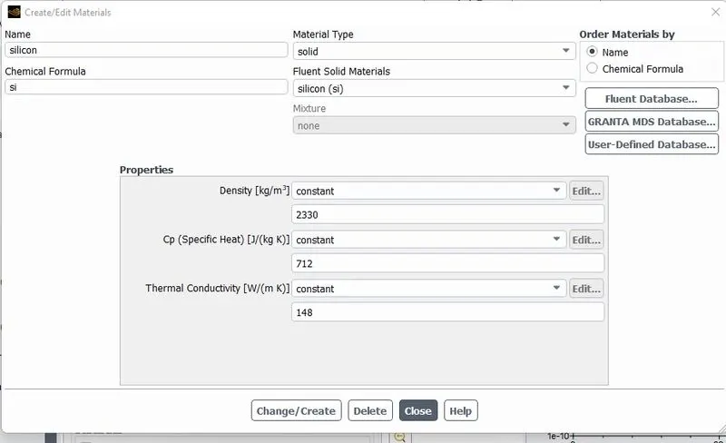
Processor-Silicon
Silicon is semiconductor mostly used in electronic devices.it conducts electricity under some conditions and acts as an insulator under others.
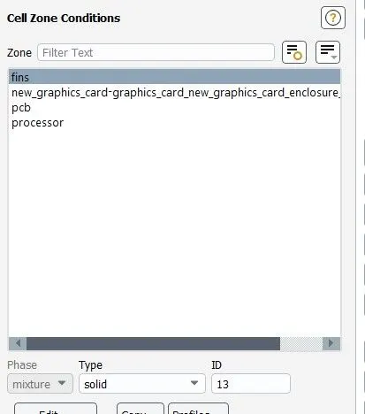
In cell zone conditions we can assign the materials to its respective components.
As per the requirement we have to find out the temperature attained by the processor, so here i enabled source trams
Here The processor is assumed as the heat source
Heat generated by processor=Power/Volume of processor
We assume the power is 1W
Volume of processor=64e^-9m^3
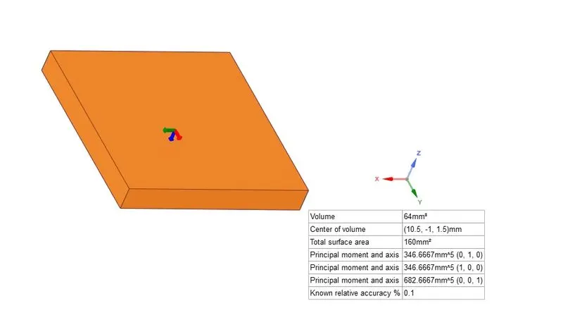
Heat generated by processor is 15625000W/m^3.
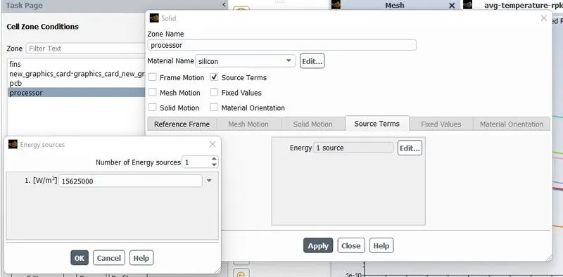
then we have to assign the velocity under the boundary condition in this case i have taken the velocity is 5m/s, as per the requirement we need to vary the velocity parameter, by varying the velocity heat transfer coefficient will increase, we will check it out by running the simulation.
Output:
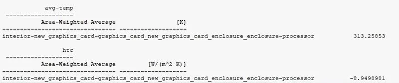
Residuals
Average temperature
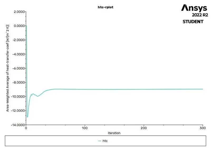
Heat transfer coefficient
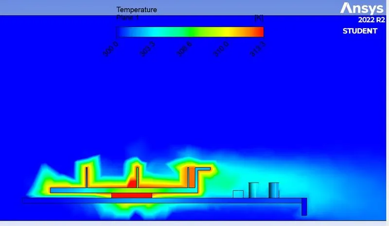
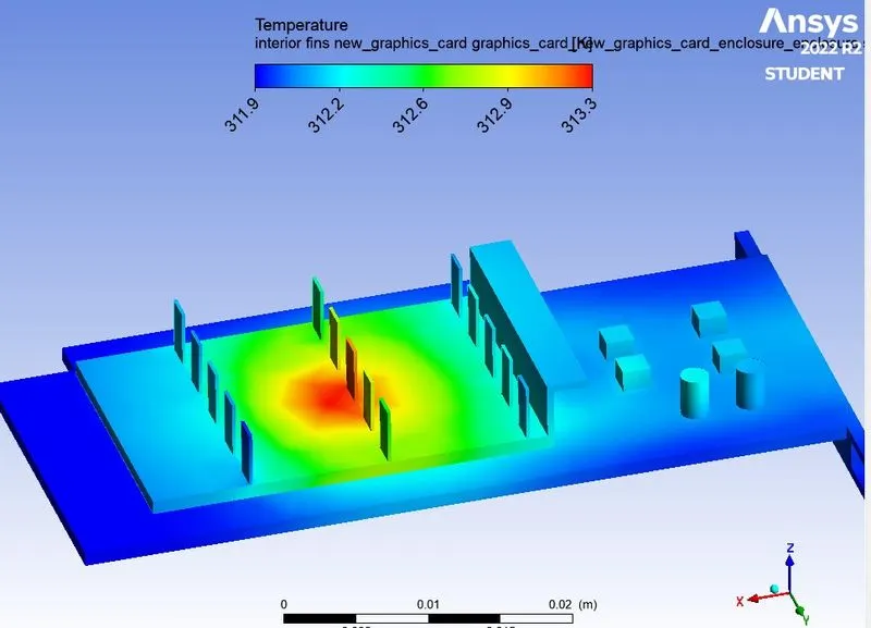
Temperature
Velocity
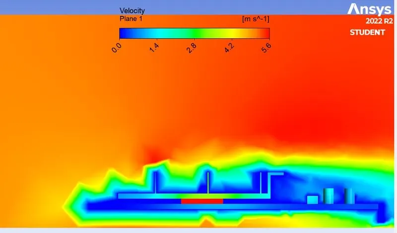
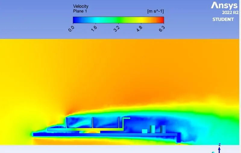
In coarse mesh case we can see that the variations near the surface in both temperature and velocity contour plots didnt captured well, so we will increase the mesh elements more finer, Based on this same setup by varying the velocity and mesh elements we will see the results.
Fine mesh
Velocity =1m/s
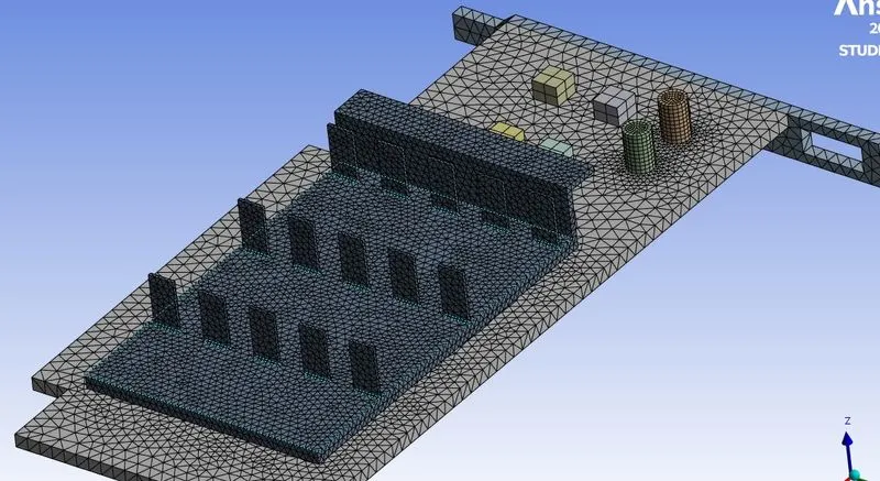
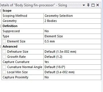
Here i have generated 0.5mm mesh for fins and processor by using body sizing
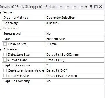
For circuit board 1mm mesh.
Total number of mesh elements= 470857
Output
Temperature
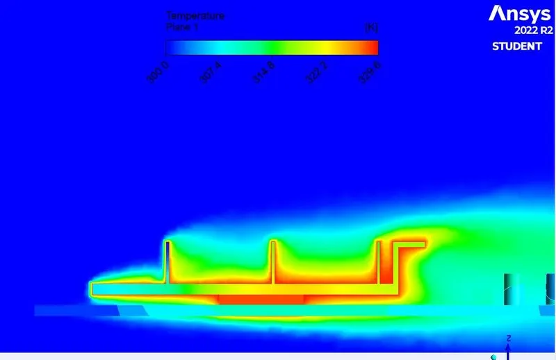
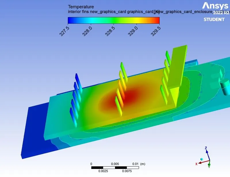
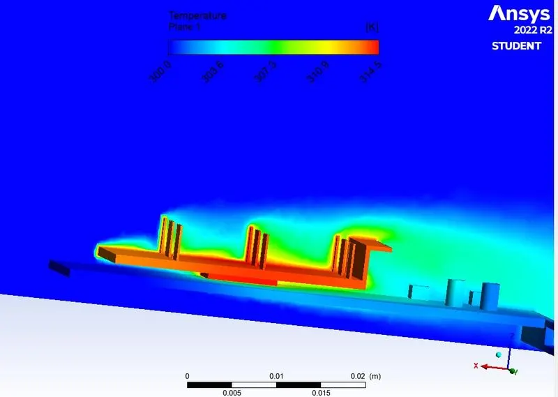
In temperature contour we can see that the heat is conducted fro processor to fin material and the convection occurs from fin to surrounding fluid. in the second contour we can see that hotspot at the fin material and the temperature at tip of the fin is very less compare to the base temperature.
Velocity
Case3 Fine mesh
Velocity=3m/s
Residuals
Average temperature
Heat transfer coefficient
Temperature
Velocity
Case-4
Velocity=5m/s
Output
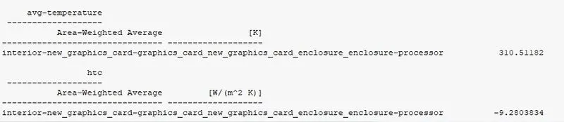
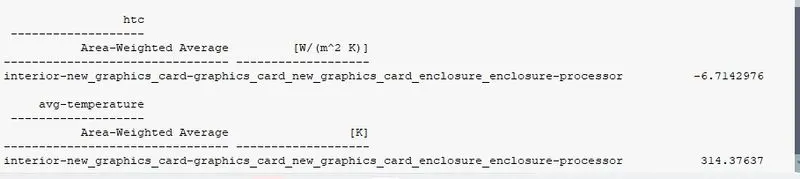
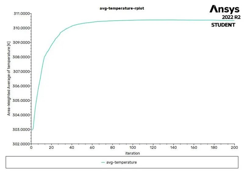
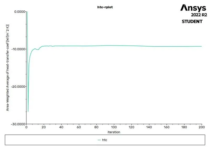
Here the heat transfer coefficient increases compare to coarse mesh with velocity 5m/s which is -8.98W/m^2K
Residuals
Average temperature
Heat transfer coefficient
Temperature contour
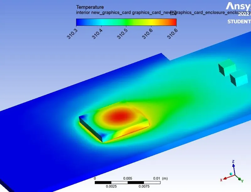
By increasing the velocity the rate of heat trasfer also increases.In temperature contour we can see that the heat is conducted from processor to fin material and the convection occurs from fin to surrounding fluid so this type of heat transfer is Conjugate heat transfer.
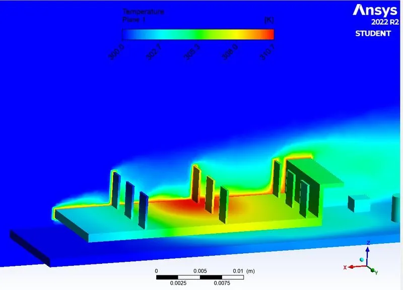
Velocity contour
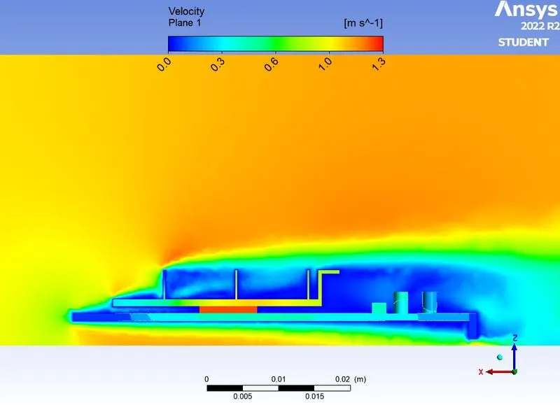
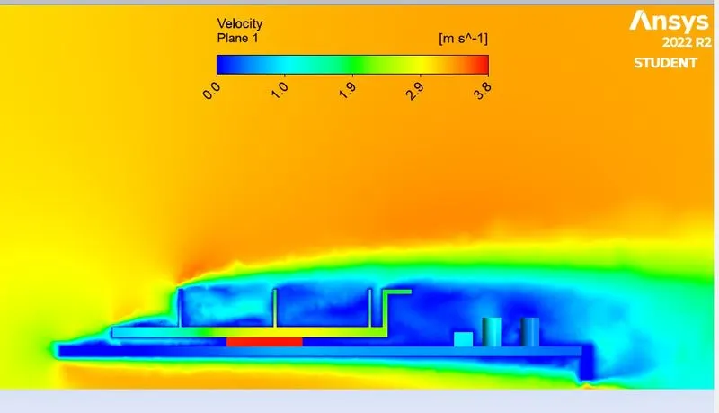
Here we can see thaat the high velocity air strikes the fin gets seperated then increases the velocity .