Week 6 - CHT Analysis on a Graphics card
CHT Anslysis on a Graphics card
Aim :- To perform a steady-state heat transfer analysis on a model of a graphics card. And to find the effect of different velocities on Temperature. Also we have to find out the maximum temperature and heat transfer coefficient attained by the processor.
Theory :-
Conjugate heat transfer is defined as the heat transfer between two domains by exchange of thermal energy. For a system the thermal energy available is defined by its temperature and the movement of thermal energy is defined by its heat flux through the outer walls. Heat transfer in solid happens through conduction and walls by convection and in liquid phase through convection. Conjugate Heat Transfer is used to describe the variation of temperature between the solids and fluids due to the exchange of thermal energy between them.
CHT provides the temperature prediction and the hotspot regions at the solid-fluid interface and we can also predict the heat transfer accurately for example- Conduction through solids, convection through fluid, and thermal radiation. It also provides the velocity and pressure distribution of fluid moving inside the solid. We can also use CHT in design optimization for improvement for heat transfer and cooling capacity.
Graphics card
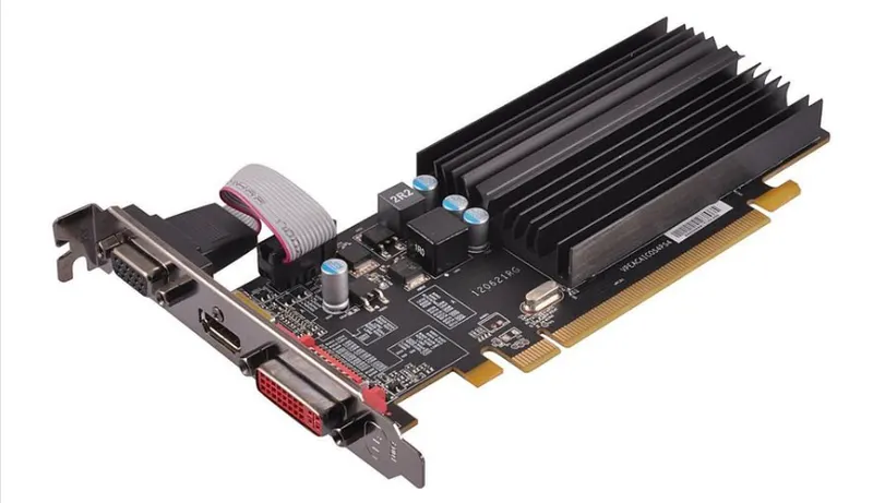
A graphics card (also called a video card, display card, graphics adapter, VGA card/VGA, video adapter, display adapter, or mistakenly GPU) is an expansion card which generates a feed of output images to a display device, such as a computer monitor. Graphics cards are sometimes called discrete or dedicated graphics cards to emphasize their distinction to integrated graphics. A graphics processing unit that performs the necessary computations is the main component of a graphics card, but the acronym "GPU" is sometimes also used to refer to the graphics card as a whole.
Geometry :-
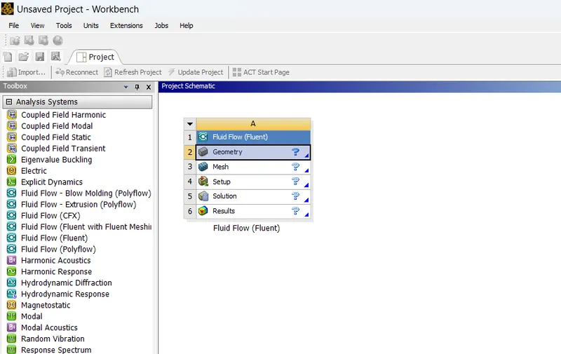
1. Start Ansys workbench and open new Fluid flow(Fluent) model. Double click on geometry and then Spaceclaim will be opened.
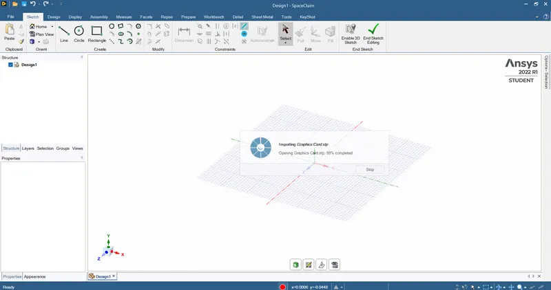
2. Import the downloaded Graphics card model to Spaceclaim.
Outer enclosure
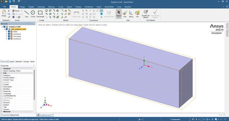
Graphics card
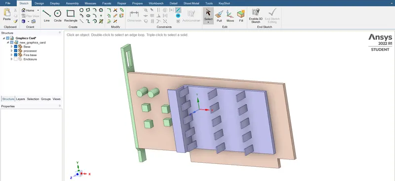
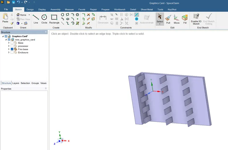
Fins
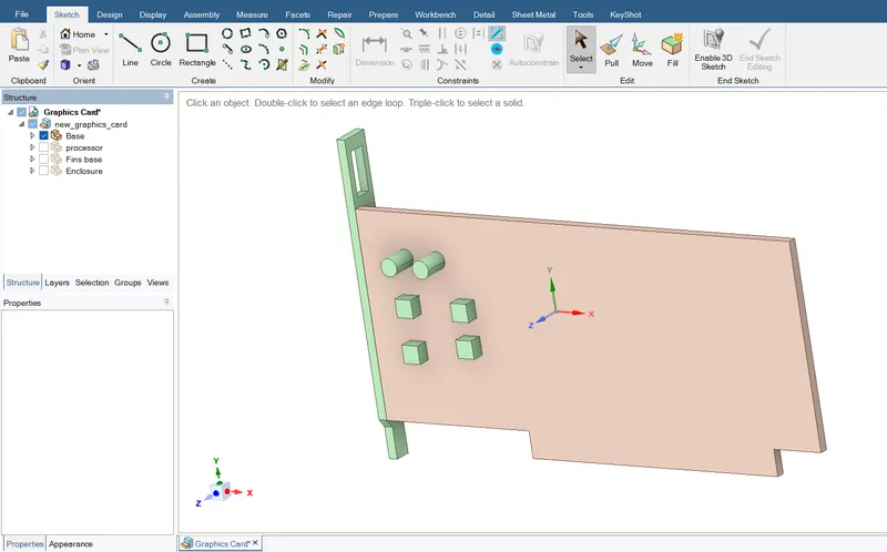
Base
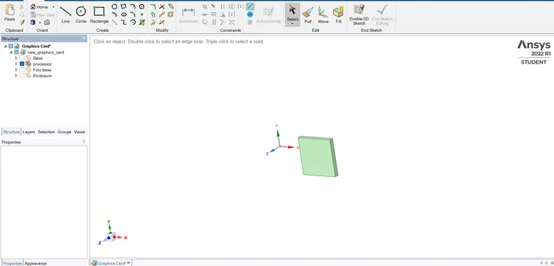
Processor
Meshing :-
Named selections :- We need to set namings for the various parts of graphics card and outer-enclosure. Fins,Base,Processor,
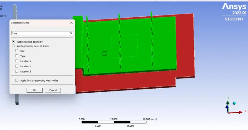
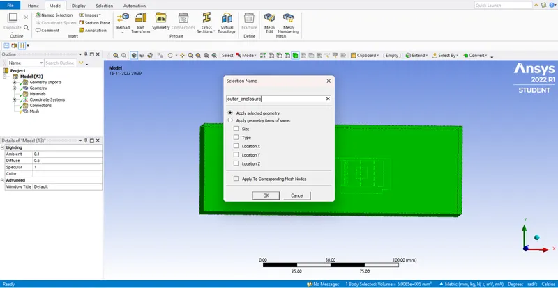
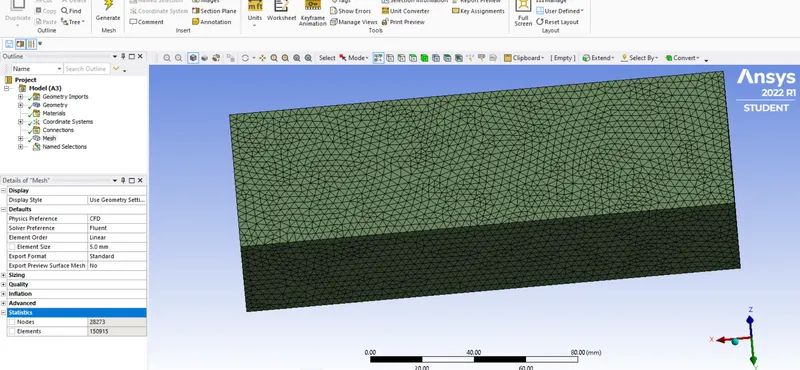
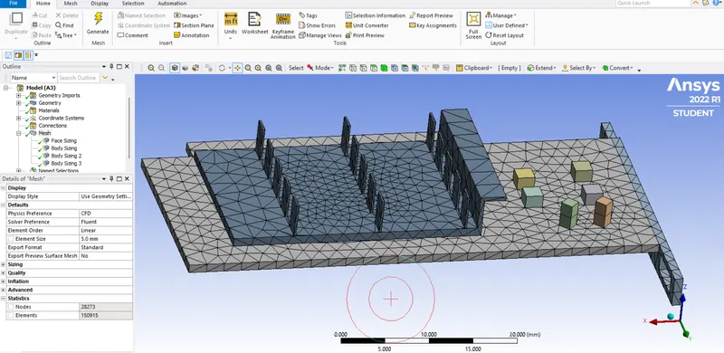
A Base mesh is generated using the standard values recommended by ansys. This mesh is used to obtain an initial solution which will help us to determine the location where mesh refinement is required.
Element order - Linear
Element size - 5mm
No.of Nodes - 28273
No.of Elements - 150915
Element quality :-
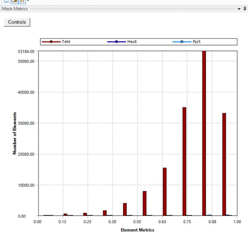
Refined mesh(since the base mesh couldn't capture all the geometry)
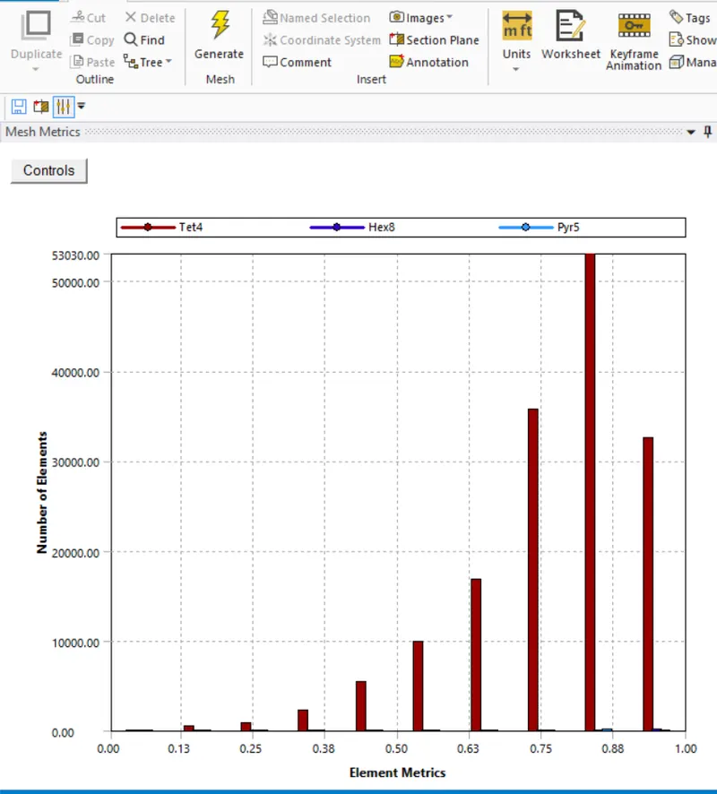
3mm for enclosure(Face sizing), 0.6mm for Fins(Body sizing), 0.8mm for Base(Body sizing), 0.2mm for Processor(Body sizing)
Element quality :-
Setup :-
Solver - Steady type, Pressure based, Turbulence model - K omega (SST)
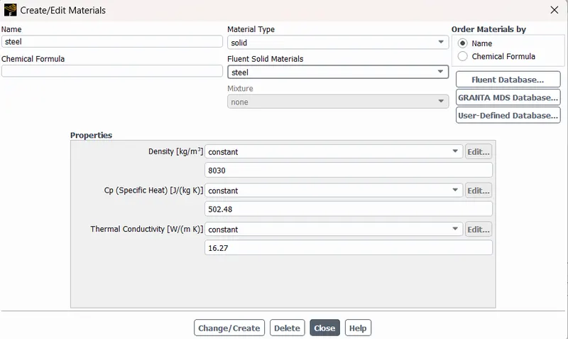
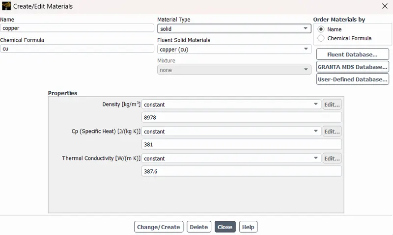
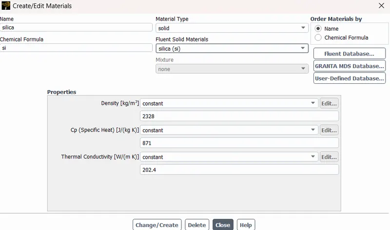
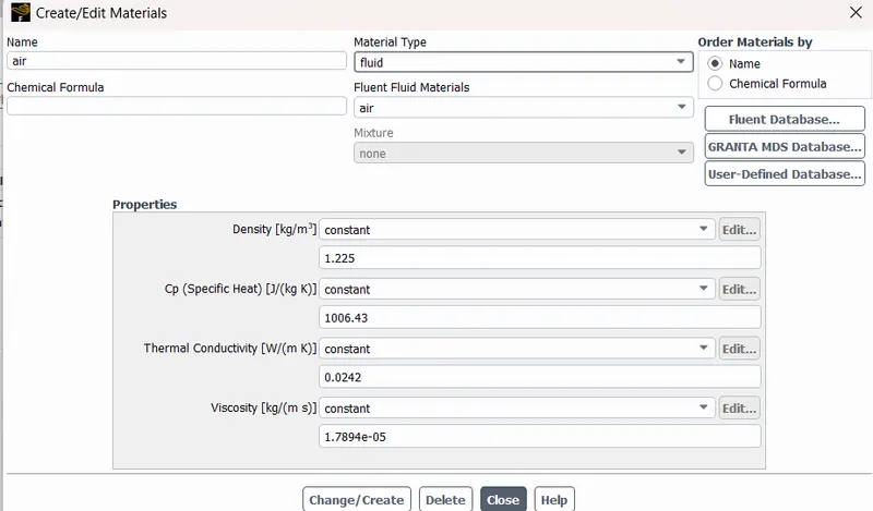
Materials - Different materials were used for different parts.
Base - Steel
Fins - Copper
Processor - Silica
Outer enclosure - Air (Fluid)
Cell Zone conditions :-
The Processor is the only source of heat. We have to calculate the heat generated by the processor.
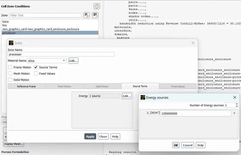
Heat generated = Graphics card power / Volume of the card = 80W/64mm^3 = 80*10^9/64 W/m^3 = 1250000000 W/m^3.
Boundary conditions :-
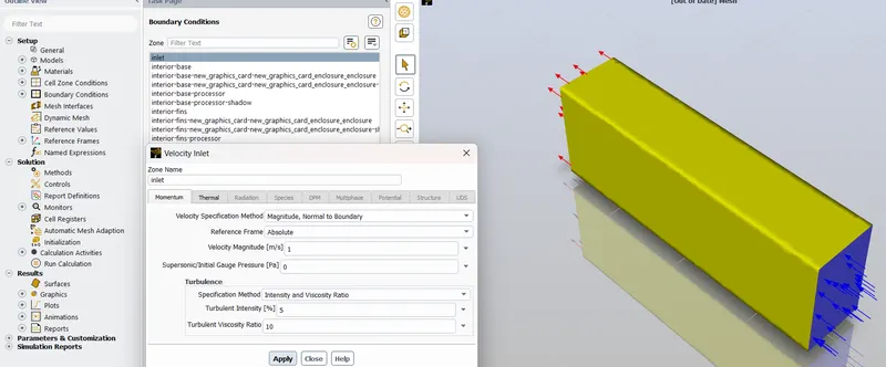
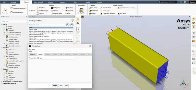
For Inlet, give velocity = 1m/s,3m/s & 5m/s respectively for 3 different cases.
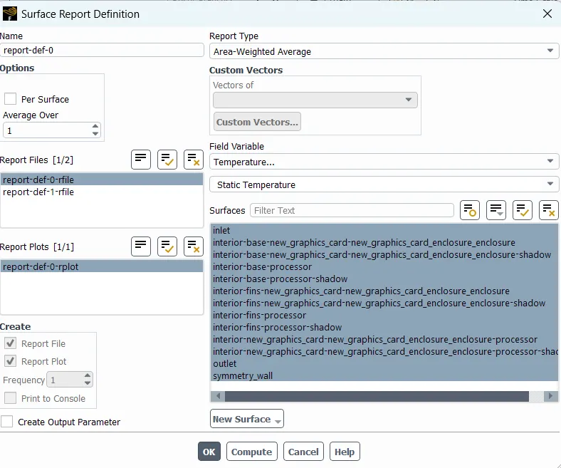
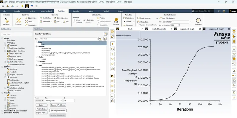
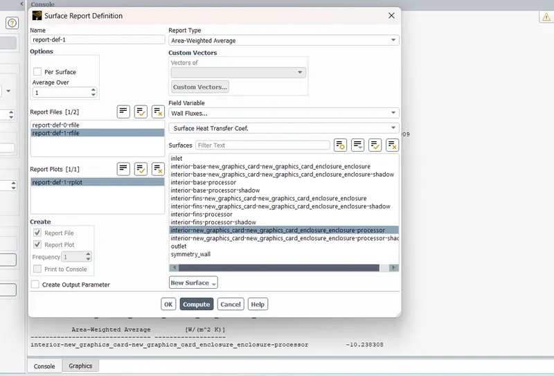
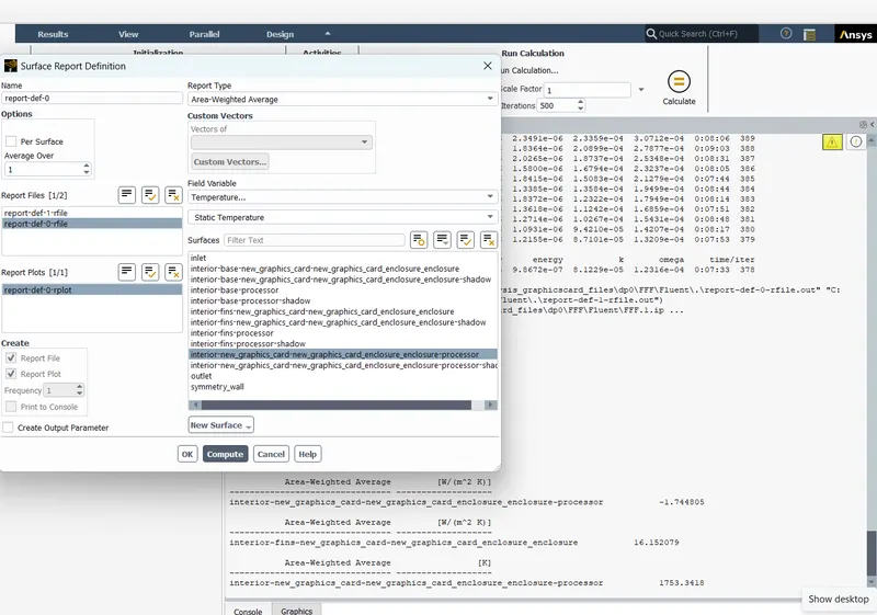
Make Report plots on both Temperature and Wall heat transfer coefficients all over the geometry, 'go to Solution - Definitions - New - Surface Report - Area weighted average - Temperature/Surface heat transfer coefficient
Export the 'Surface Heat transfer coefficient' variable to CFD postprocessing before closing the fluent. (We have to import the missing variables from Fluent data)
Now start hybrid initialization and start the calculation by giving 500 iterations.
Results :-
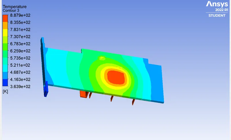
For Inlet velocity = 5m/s
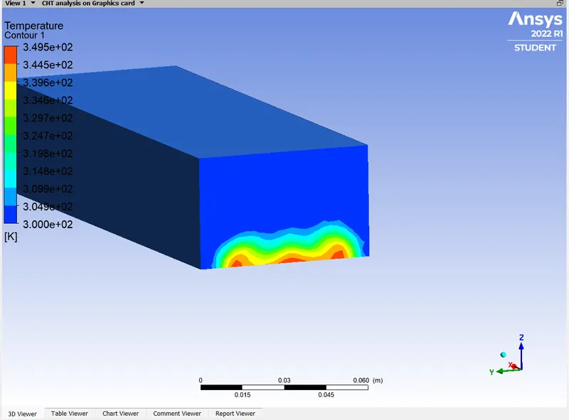
Hotspot region around the processor.
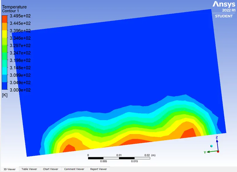
Temperature at the outlet
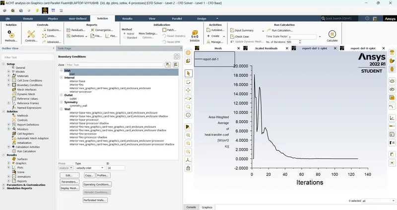
Convergence
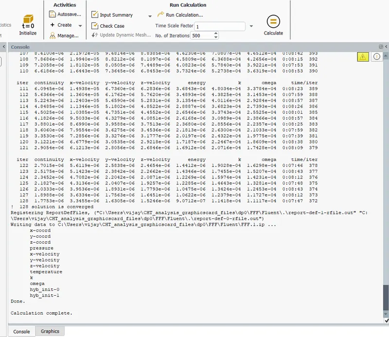
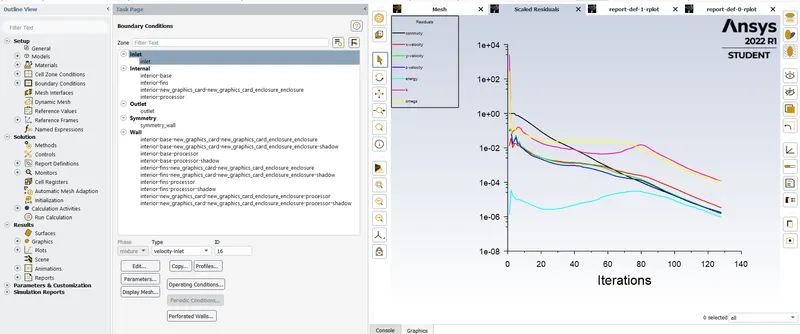
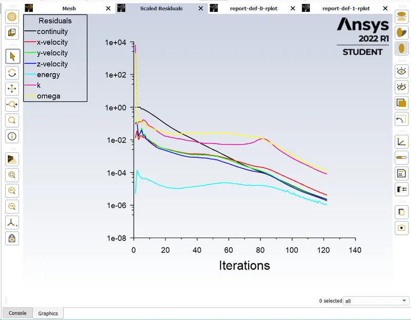
After 128 iterations our solution got converged.
Scaled residuals
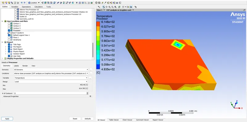
Temperature plot
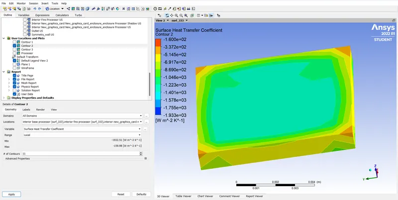
Surface Heat Transfer coefficient
Temperature at the processor
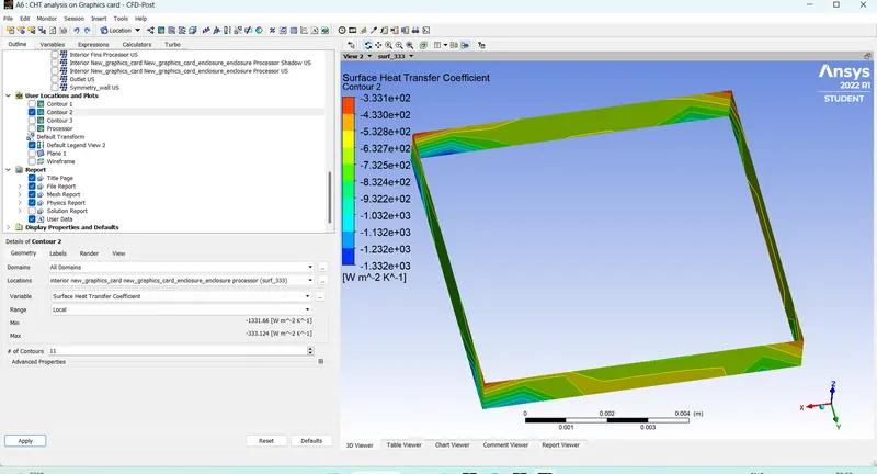
Surface heat transfer coefficient at processor
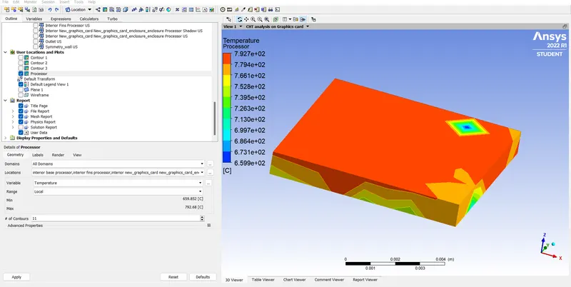
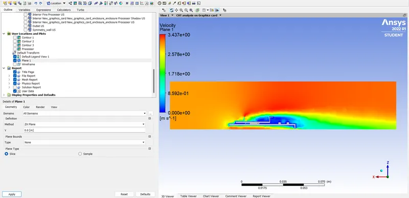
When Inlet velocity = 3m/s
Temperature at processor
Velocity Contour
Surface heat transfer coefficient at processor
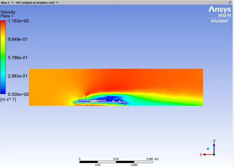
When inlet velocity = 1m/s
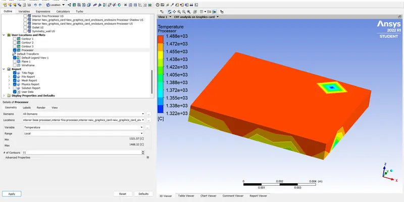
Temperature at the Processor
Surface heat transfer coeffiecient at the processor
Velocity Contour
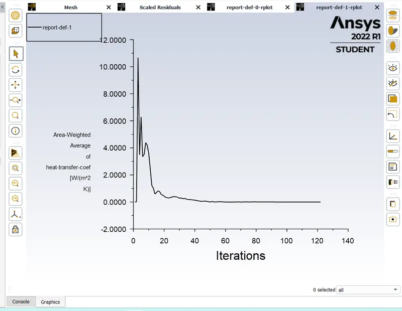
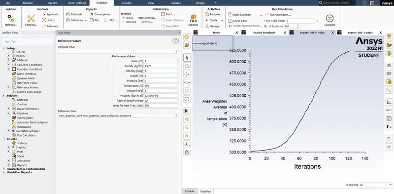
Compute the Temperature and Heat transfer coefficient values at the processor using Report plots.
Conclusion :-
| Velocity at the Inlet (m/s) | Temperature at the processor(K) | Heat transfer coefficient at the processor (W/m^2.K) |
| 1 | 1753 | 1.744 |
| 3 | 1058 | 4.99 |
| 5 | 880.4 | 10.238 |
From the above results we conclude that higher the velocity of the fluid entering at the inlet higher will be the heat transfer coefficient and the temperature change takes place rapidly (For constant power source). Due to the fluid flow, the visocisity creates heat. But it can be neglected due to its negligible value but should be taken into account for high velocity cases.