Week 6 - CHT Analysis on a Graphics card
Aim of the project.
To perform the conjugate heat transfer Simulations on the graphics card. A conjugate heat transfer analysis is useful where there are multiple models of heat transfer, like conduction and convection.
Set up:
Import the geometry from ANSYS Workbench. And modify the geometry as per our requirements through space clim.
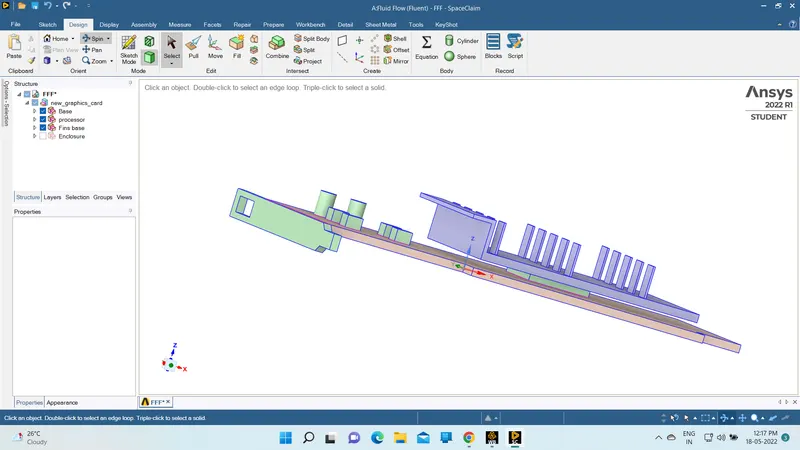
There are three major parts in the graphic card.
One is the base and the next one is the fin base and 3rd one is the processor.
Meshing
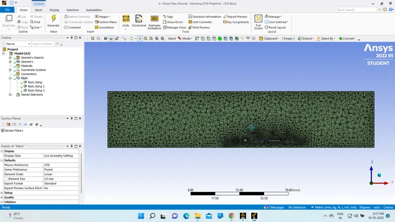
Mesh the geometry according to the requirements.
Enclosure meshing size is 0.3mm
fin base meshing size is 0.1mm
processor meshing size is 0.1mm
card base meshing size is 0.1mm
Materials
solid zones:
Aluminum for fins, silicon for the processor, and wood for base.
Fluid zones:
Air
The properties of all materials are standard one
Reference values
Heat generation for the processor is taken 75w / volume of the processor i.e 0.04*0.04*0.002
q = 2.3437e7 W/m^3
Simulations:
Case 1:
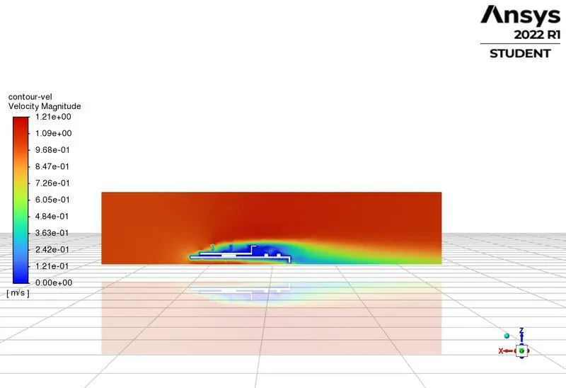
Velocity at 1m/s;
Velocity contours
Temp contours
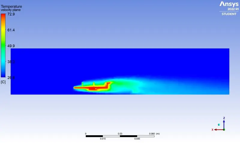
Heat transfer coefficient is 159.270 for 1m/s vel at finer mesh
Case 2:
Velocity at 3m/s
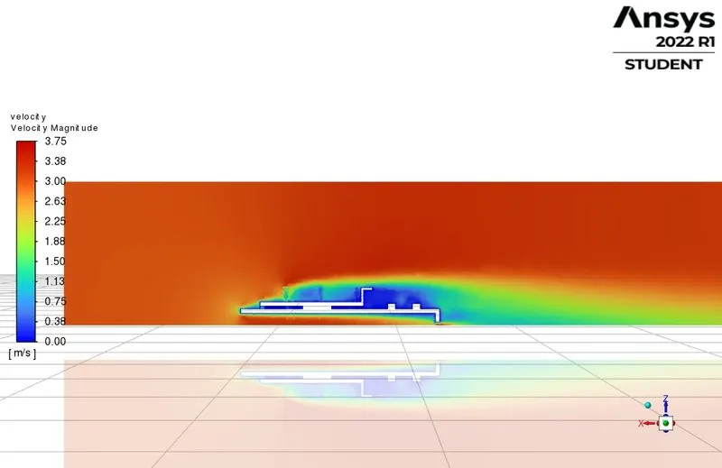
Temp contours
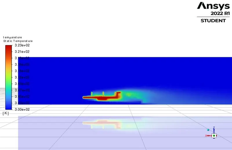
The heat transfer coefficient is 262.9701 for 3m/s vel
Case 3:
Velocity at 5m/s
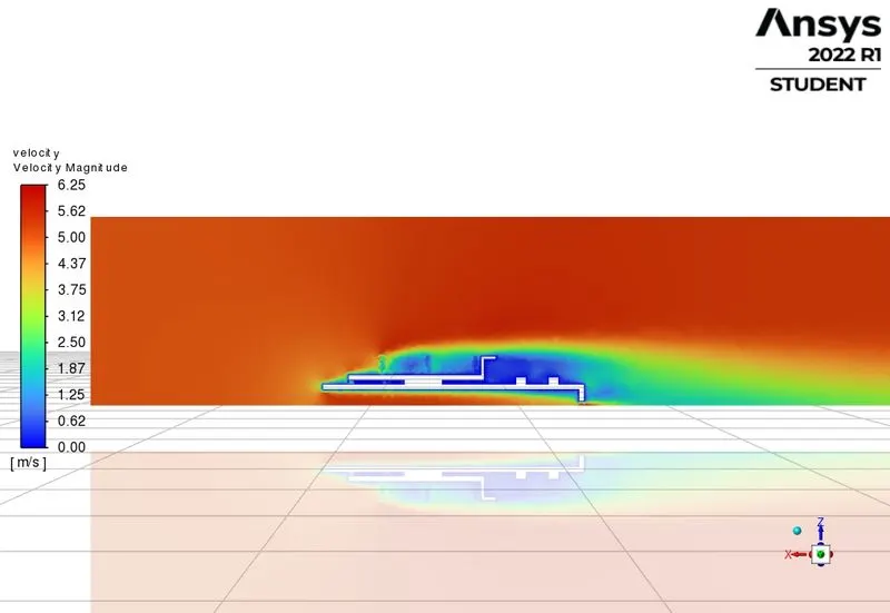
Temp contours
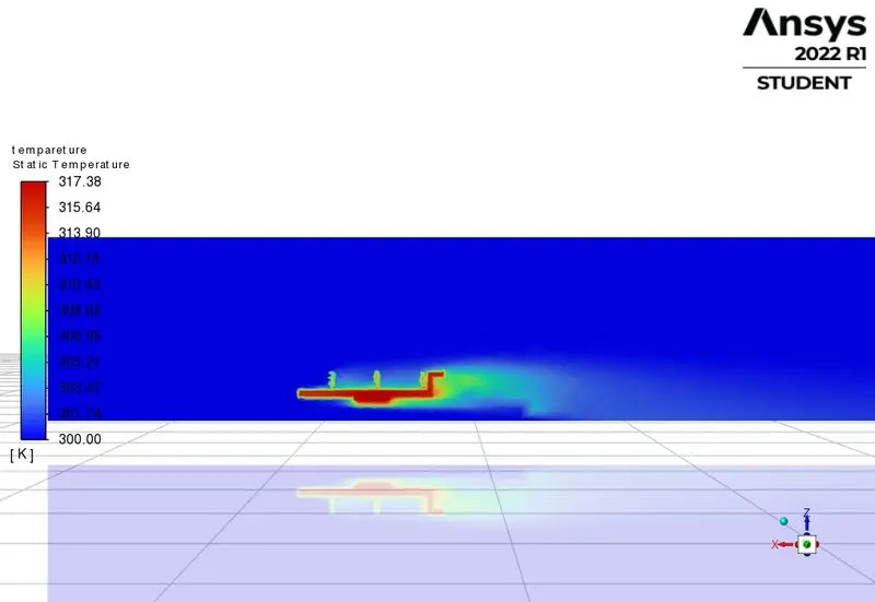
The heat transfer coefficient is 317.80618 for 3m/s vel
Simulation has achieved convergence
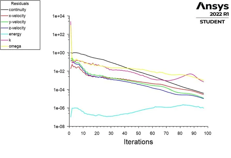
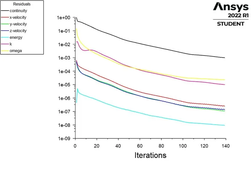
As iterations are going on the results would get better approximations as we see the above residuals. so we may say the simulations got converged
potential hotspots ;
The potential hotspots are near the adjacent to the processor like the fin base and the card base because the heat is dissipated across the fin wall and case base as we see in the temp contours.
Impressions:
As the airflow velocity is getting increased across the graphics card, the heat transfer coefficient would increase