Week 6 - CHT Analysis on a Graphics card
AIM
To simulate the flow over the graphic card and considering and analysis of conjugate heat transfer from heat source processor to fin body and base body , and making the analysis the result by giving the flow of air over the all body , fin body , base body and processor and catching out all results like temperate , pressure , wall heat transfer coefficient and velocity for both fine and coarse mesh .
Importance
1)it is used to simulate the flow over the body which produce heat and conduction take place in it
2)it used in many industrial areas where to analysis the heat transfer results like flow over the exhaust in cars , flow in turbines ,si engines cylinder .
3) In ic engines to calculated the results of piston and cylinders , get results of temperature , pressure on body
4)widely used in aerospace industry for analysis the results on engines , turbine blade , compressor blades and combustion chamber analysis , in ci engines .
4)widely used in analysis for thermal industries for steam turbine and compressor analysis , transfer of heat from hot heavy water to soft water .
5) it is used in rocket engines for transfer of heat from nozzles used in analysis in heat transfer calculation in convergence and divergence nozzles, and fluid pipes is passed through the outer surface of nozzle section .
In such simulation we are considering the graphic card of computer, fin and base body is attached to it we will take the results by providing enclosure around it and giving inlet and outlet to it .we compare the result by giving two meshes.
Solving approach and methods
- In space claim we import the step file , after importing we make the geometry clear and make prepare for further analysis, for that we remove the extra edges from it . then we given share topology for whole body with enclosure and fix it for all , enable share for all four part like processor , fin body , base body and enclosure .
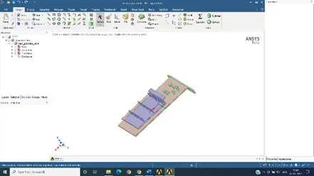
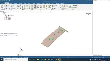
2)After opening in mesh section , we provide meshing for both size
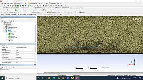
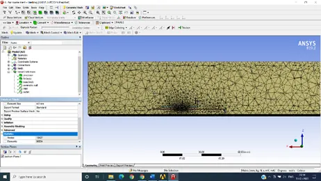
Fine mesh size is 1mm , for coarse mesh 4mm
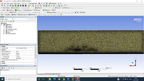
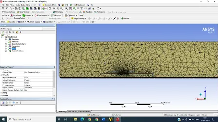
1mm mesh size 4mm mesh size
Applied proximity for 1 and check mesh, all the body for sharing with each other parts mesh is not coincide with the each other for different body, cut section is attached for both mesh
Names is given for all section
Processor, fin body, base body, outer symmetry wall, inlet and outlet respectively.
3)In fluent section we enable gravity at -y 9.81, and consider steady flow , pressure base solver . enabling energy equations , enabled k-epsilon method .In material section we consider air as flow ,
Key points to consider in such section ,
In cell zone section enable processor ,fin body and base body as solid body ,in processor section we click the source section , and giving the value of 187500000 w/m3 for heat source , we get from
We consider conduction rate is 12 and volume of processor 8x8x1=64mm3 .
- In boundary condition we give inlet velocity 7 m/s and pressure outlet for it for both mesh ,giving initializing we plane in post processor which is normal to y axis , and consider temperature , pressure and velocity on graphic card .
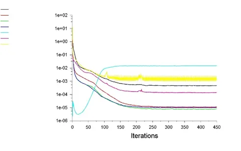
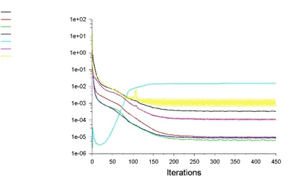
- we provide 600 iteration for both cases attached residual curve for both .
- For fine mesh of 1 mm
- for coarse mesh 4 mm
- In result section , temperature , pressure , velocity and heat transfer coefficient for both mesh is analyse for horizontal and vertical plane
All results is attached
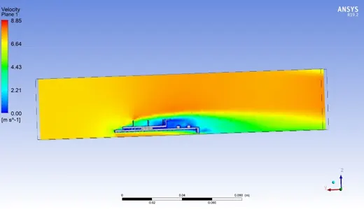
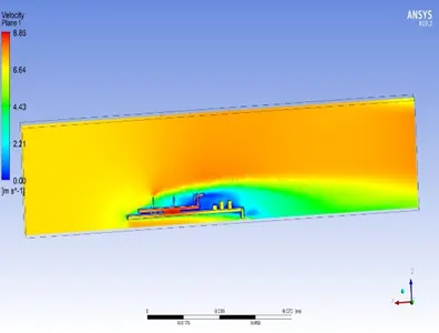
Velocity conture for fine mesh on vertical plane velocity conture for coarse mesh on vertical plane
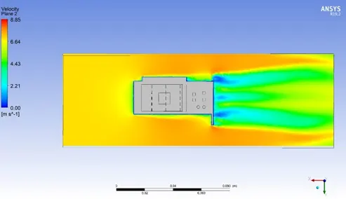
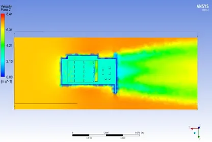
velocity conture for fine mesh for horizontal plane velocity conture for coarse mesh for horizontal plane
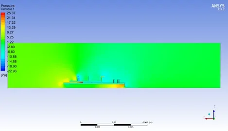
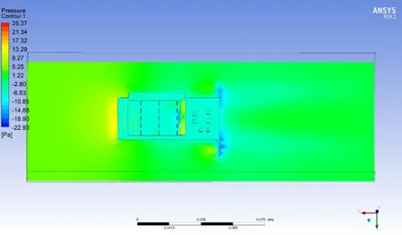
pressure conture on vertical plane for coarse mesh pressure conture on horizontal plane for coarse mesh
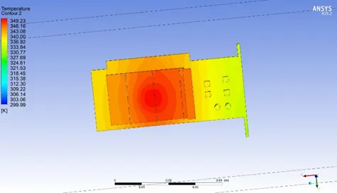
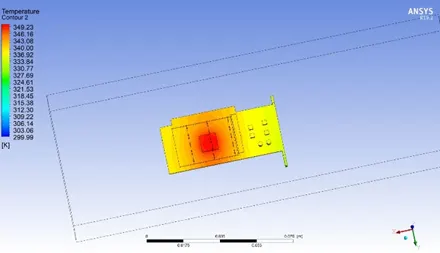
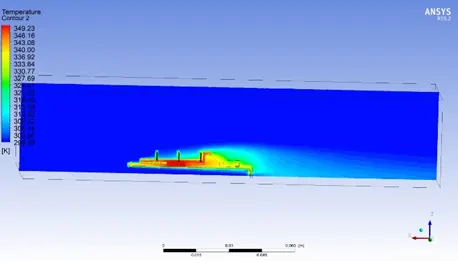
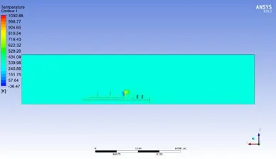
Temperature conture for full body in fine mesh temperature conture for processor and base body with fine
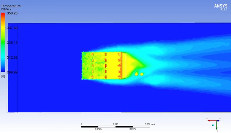
Temperature conture of fine mesh with horizontal plane on fin body.
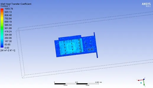
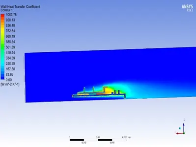
wall heat transfer coefficient with or without body for fine mesh
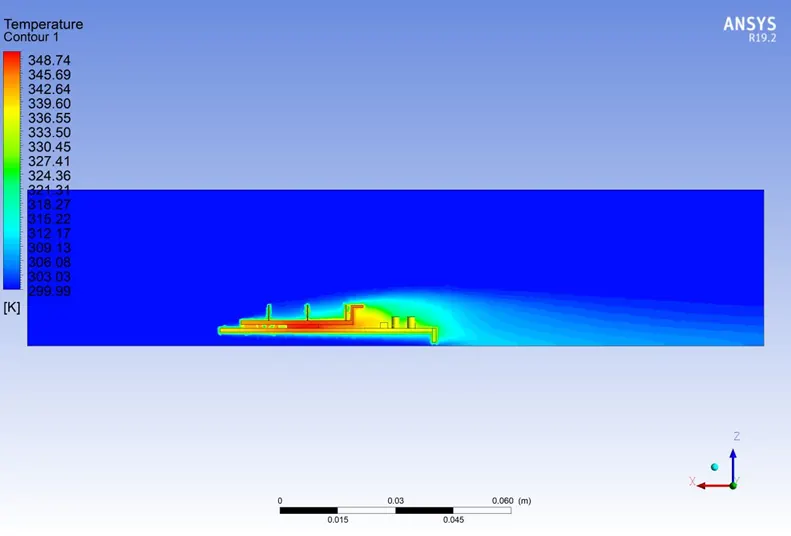
Temperature conture for fine mesh without body
Conclusion
1)By analysing for both mesh refine and coarse , it gives better results in refine mesh , for large mesh results are not accurate as given above .
2) showing lot of temperature and pressure difference for fine and coarse mesh .
3)Need accurate meshing for results , mashing for each parts and it should be proximate minimum 1, for large mesh it giving wrong results .
4)There is heat transfer from source processor hot body to fin body and base body , and air flow from outside with considerable velocity , it reduces the temperature of fin and give cooling to hot fin body , which reduce the overheating of processor temperature .by increasing the inlet velocity and inlet temperature of air flow which results in better cooling of body by heat transfer .
5) In such simulation we get the results how the contacted body transfer heat from one body to other body .
6) CHT study helps in analysis the hot point on the body and low temperature on many body. Which enable the analyst to make changes in body , to analyse the bearable temperature of bodies.
7)Hence for simulation require proper and accurate meshing for better results .