Week 6 - CHT Analysis on a Graphics card
Aim:
Perform a steady-state conjugate heat transfer analysis on a model of a graphics card. You can use appropriate materials of your choice for the simulation. Make sure to properly define the correct solid and fluid zones.
Objectives:
- Run the simulation by varying the velocity from 1m/sec to 5m/sec for at least 3 velocities and discuss the results.
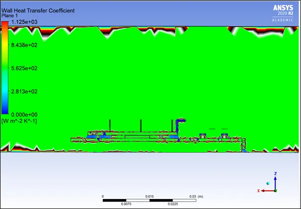
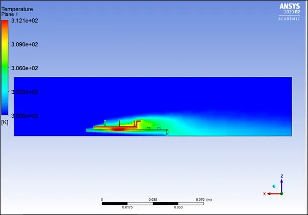
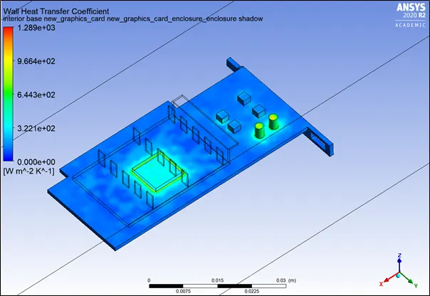
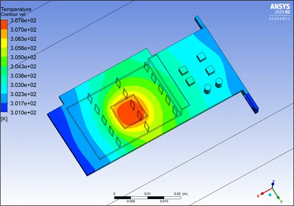
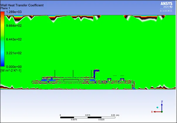
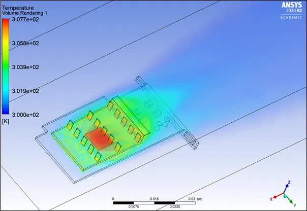
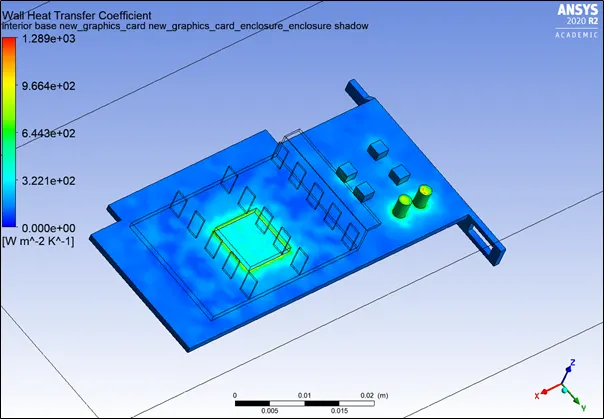
- Find out the maximum temperature and heat transfer coefficient attained by the processor.
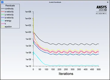
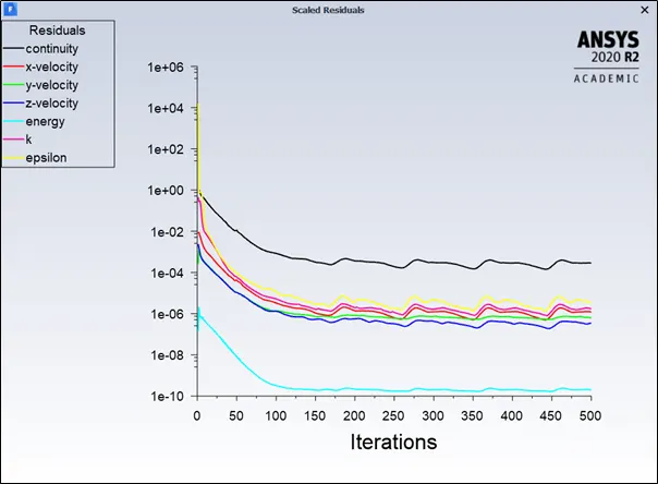
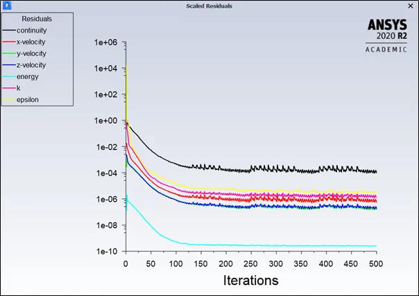
- Prove that the simulation has achieved convergence with appropriate images and plots.
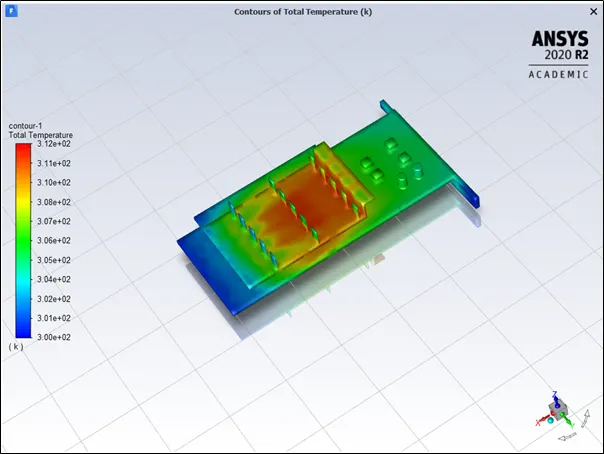
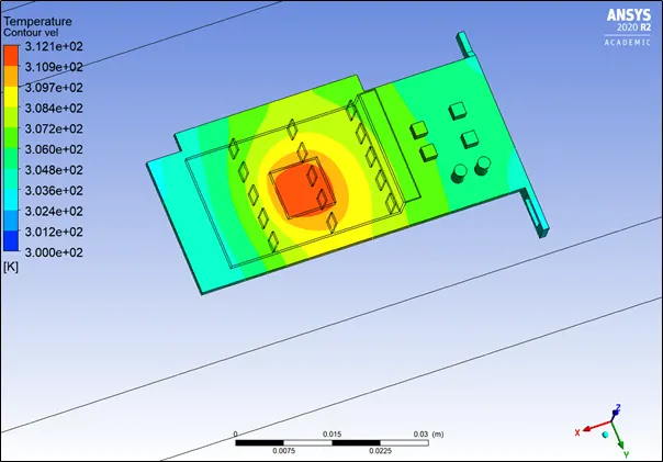
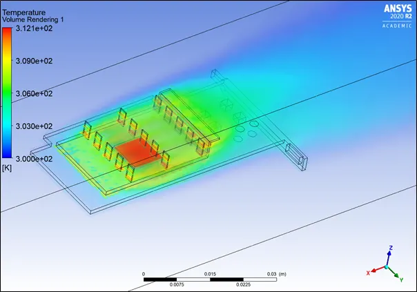
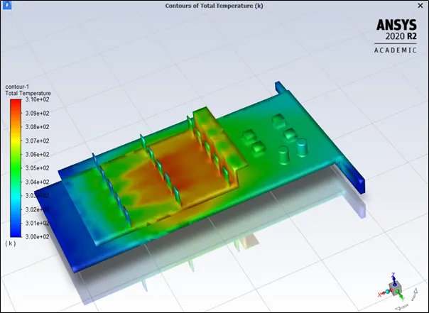
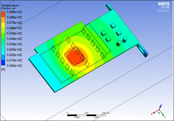
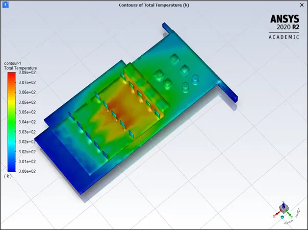
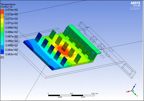
- Identify potential hotspots on the model.
- Geometry
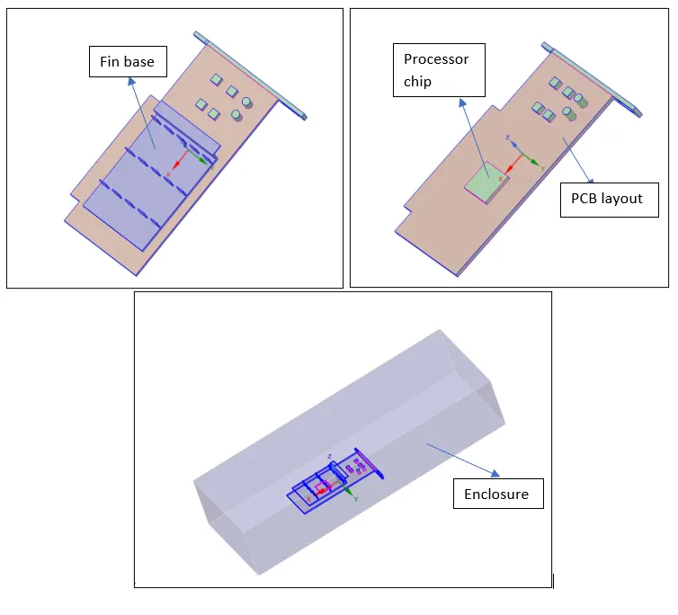
A geometry step file for graphics card was inserted in Ansys Spaceclaim environment. To generate air flow around the graphic card, an enclosure was created. Geometry is shown as below
II. Mesh Description
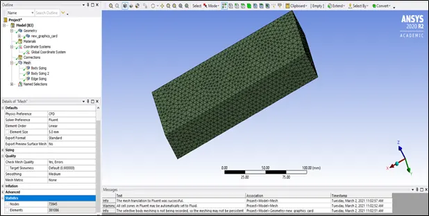
Base mesh size: 5 mm
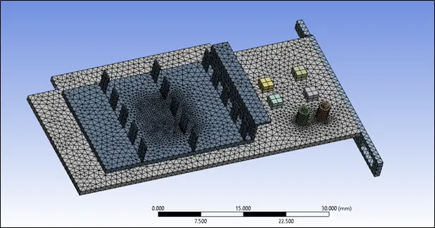
Body sizing: Fin base and graphic card base (PCB) were given mesh size of 1 mm
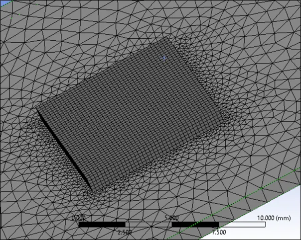
Body sizing 2: Processor chip was given mesh size of 0.2 mm
Edge sizing: This was introduced for cylindrical part (resistor, capacitor etc.)
Number of Nodes: 73845
Number of Elements: 381086
Same mesh was used for 3 different cases. Following are few snapshots of mesh used.
Named selection:

III. Physics Setup
a) Solver was selected as Pressure Based and Steady state simulation as the velocity in the problem statement was in the range of 2 m/s to 5 m/s.
b) Materials:
Fluid – Air
Solid – i) Aluminum (Fin Base material)
ii) Copper (Processor chip)
iii) Steel (PCB Layout)
c) Energy equations are considered
d) Turbulence model used was k-ɛ (realizable)
e) Cell zone conditions are given appropriately, solid for the base PCB, fin base and chip and fluid (air) were given to enclosure.
Heat generation source was given to chip: 1 W (64 mm3 is volume of processor chip)
: 1/64e-9 W/m3
: 15625000 W/m3
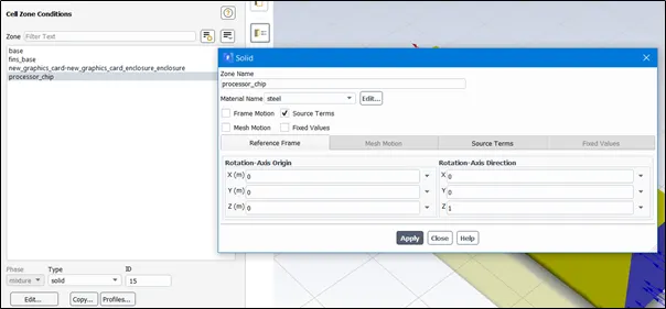
f) Boundary conditions: Different air velocities are used for different cases 2m/s, 3m/s and 5m/s.
IV. Results
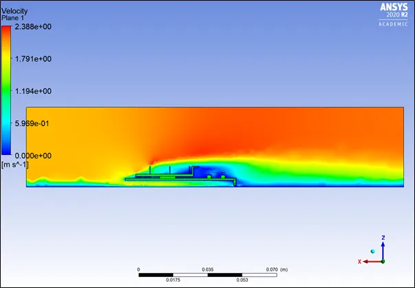
Case 1 : Inlet velocity 2m/s, Normal temperature was 300K
Solution was converged after 225 iterations
Case 2 : Inlet velocity 3m/s, Normal temperature was 300K
Solution converged after 300 iterations
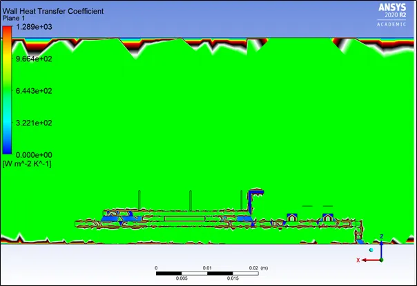
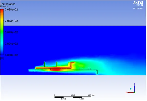
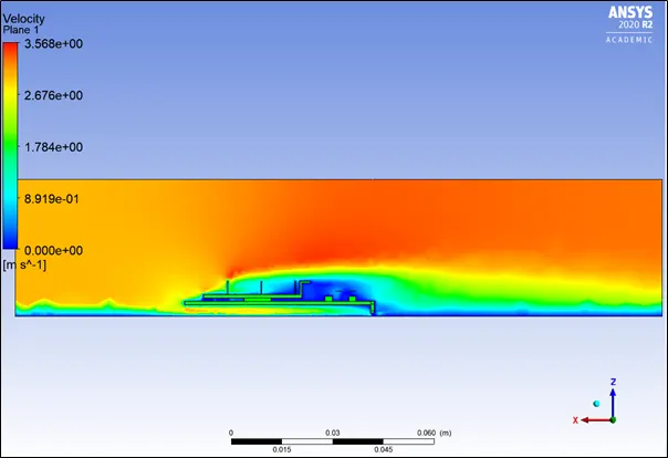
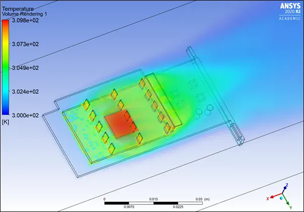
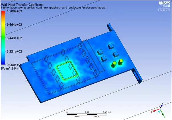
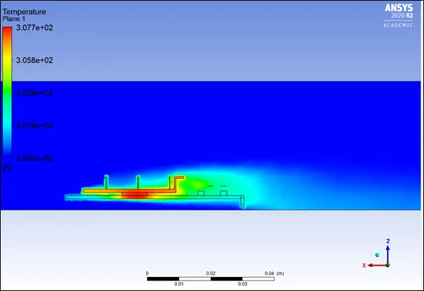
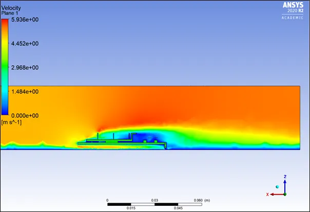
Case 3 : Inlet velocity 5m/s, Normal temperature was 300K
Solution converged after 350 iterations
V. Conclusion:
As velocity of incoming air increased, the maximum temperature reached was decreased. This is due to the fact that, as air velocity increases, heat transfer convective coefficient increases so heat transfer to the surrounding increases and temperature attained by the material decreases.
As per the direction of air velocity, heat transfer for fins changes from left to right as shown in the temperature contour on Fin-base section.
|
Case number |
Velocity |
Maximum temperature attained |
|
Case 1 |
2 m/s |
312 K |
|
Case 2 |
3 m/s |
309 K |
|
Case 3 |
5 m/s |
307 K |