Week-6 Challenge: EV Drivetrain
ANSWER:
AIM:
Types of power converter circuits are employed in electric and hybrid electric vehicle.
To find the steady state speed of EV if it have duty cycle of 70%.
Develop a mathematical model of a DC Motor for the below equation using Simulink.
ω= V/Kϕ -Ra/Kϕ^2 .T
Explain in brief about author’s perspective.
1. Which types of power converter circuits are employed in electric and hybrid electric vehicle.
They are three types of power converter
DC-DC converter
AC-DC converter
DC-AC converter
1.DC-DC converter('Chopper'):-
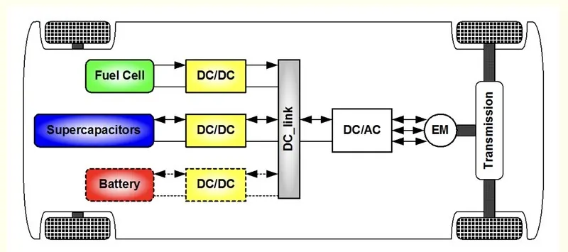
DC/DC converters can be designed to transfer power in only one direction, from the input to the output. However, almost all DC/DC converter topologies can be made bi-directional. A bi-directional converter can move power in either direction, which is useful in applications requiring regenerative braking.
DC-DC converters are high-frequency power conversion circuits that use high-frequency switching and inductors, transformers, and capacitors to smooth out switching noise into regulated DC voltages. Closed feedback loops maintain constant voltage output even when changing input voltages and output currents. At 90% efficiency, they are generally much more efficient and smaller than linear regulators. Their disadvantages are noise and complexity.
2.AC-DC converter ('Rectifier'):-
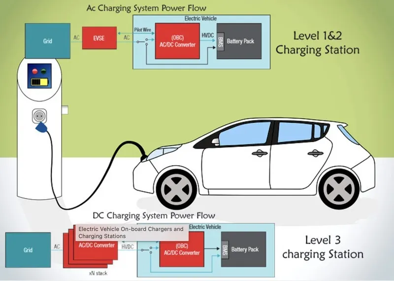
AC to DC converters are most commonly used in Plug-in Hybrid Electric Vehicles (PHEV) & Plug-in Electric Vehicles (PEV). These vehicles get their propulsion power from an external electricity source (charging stations) which is alternating current. The battery needs to be charged using a direct current source. For this purpose, AC to DC converter is employed in a PHEV & PEV. This means that most power loss is associated with conduction. To solve this problem, metal-oxide-semiconductor field-effect transistors (MOSFETs) or insulated gate bipolar transistors (IGBTs) are used as the switching devices. While MOSFETs with high withstanding voltage have high on-resistance, IGBTs have low on-resistance regardless of the withstanding voltage applied to the power device in the insulation circuit.
3.DC-AC converter('Inverter'):-
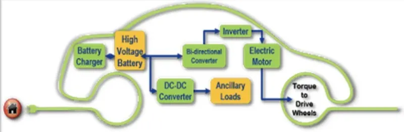
AC-DC converters (rectifiers), DC-DC converters, and DC-AC converters (inverters). Auxiliary units, such as pressure pumps, air-conditioning units, and auxiliary batteries, require a DC-AC inverter or a DC-DC converter at a lower power rating. A DC-AC power inverter converts a DC input voltage to the required magnitude and frequency of AC output voltage. Generally, AC power is more efficient, reliable and widely utilized in many commercial, domestic, and industrial applications, such as the renewable energy system (RES), motor drives system (MDS), and uninterruptible power supplies (UPSs).
2.An Electric Vehicle's powertrain with 72V battery pack in shown in the diagram below. The duty ratio for acceleration operation is 'd1' and for the braking operation the duty ratio is 'd2'.?
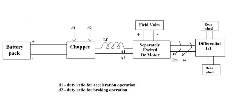
The other parameters of the electric vehicle is given below
Rated Armature voltage= 72 V
Rated armature current= 400 A
Ra= 0.5Ω,
KΦ= 0.7 Volt second
Chopper Switching frequency= 400 Hz
The vehicle speed-torque characteristics are given by the below equation

What is EV steady state speed if duty cycle is 70%
Solution:-
Here it's given that the parameters of the electric vehicle.
Rated Armature voltage= 72 V
Rated armature current= 400 A
Ra= 0.5Ω,
KΦ= 0.7 Volt second
Chopper Switching frequency= 400 Hz
Tv=24.7+0.0051ω2 taking this equation as "1"
For the duty cylce of 70%(0.7)
Volatge (V)= Rated Armature voltage*duty cycle
= 72*0.7
= 50.4V
So here we get the voltage as "50.4V" for 70% duty cycle
As we know the torque equation =
T = VKϕ/Ra – ((Kϕ)2/Ra)*ω
T=((50.4*0.7)/0.5)-((0.7)2/0.5)*ω
By solving we get
T=70.56-0.98ω taking this equation as "2"
Comparing both equation "1" & "2"
ie; T=Tv
70.56-0.98ω=24.7+0.0051ω2
0.0051 ω2 + 0.98 ω +24.7 -70.56 = 0
0.0051 ω2 + 0.98 ω -45.8=0
By solving the Quadratic equation we get two values for ω
ω=38.915 , ω=-231.072
since the value of speed will be positive integer so speed= 38.915 rad/sec
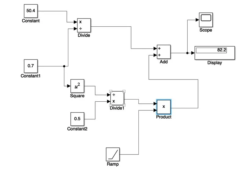
3.Develop a mathematical model of a DC Motor for the below equation using Simulink.
ω= V/Kϕ -Ra/Kϕ^2 .T
Here we are using the block of
Addition
Constant
Square
Product
Division
Volatge (V)=50.4V
Ra= 0.5Ω,
KΦ= 0.7
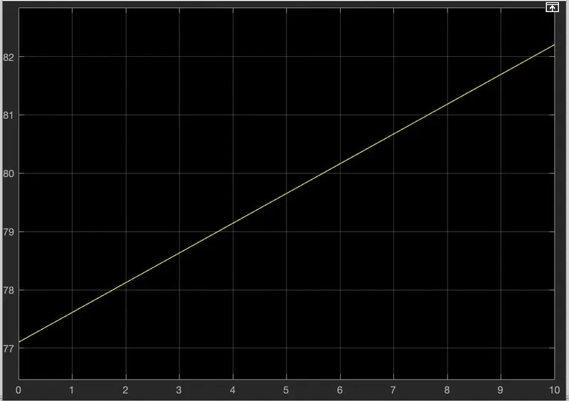
value of Torque value (T) in ramp as slop=0.5.
By applying the above values to the simulation we get the result as:
4. Refer to the blog on below topic:
Explain in brief about author’s perspective.
* He explains that all engines were similar and it was up to the user to select according to their requirement and the working of both 3 phase induction motor and a brushless DC motor.
* The author has done comparison between these two
* Ac Induction motor have some advantages like:
- It has no magnets.
- The motor has the ability to start under load.
- No inverter is needed.
* Some disadvantages of Induction motors are:
- They cannot operate from DC: AC is a must.
- Shaft speed is proportionate to line frequency
When operated from utility power, they have limited starting torque and somewhat limited running peak torque capabilities, when compared to DC type machines.
In the course of time, DC brush motors are replaced by DC Brushless or Induction Motors.
* Brushless DC motor have some advantages like:
- Much less rotor heat is generated with the DC brushless drive.
- The peak point energy efficiency for a DC brushless drive will typically be a few percentage points higher than for an induction drive.
* Disadvantages of Brushless DC motor are:
- As machine size grows, the magnetic losses increase proportionately and part load efficiency drops
- The major limitation being, the Induction Motor can not operate from DC, and AC is a must.
Finally the author couldn't choose which drive is better than the other but makes it clear that DC brushless drives will likely continue to dominate in the hybrid and coming plug-in hybrid markets, and that induction drives will likely maintain dominance for the high-performance pure electrics.