Week-6 Challenge: EV Drivetrain
QUESTION 1
AIM : Which types of power converter circuits are employed in electric and hybrid electric vehicle
OBJECTIVES :
- Power electronics is about that deals with the process of high voltages and currents to deliver power that supports a variety of needs.
- Power supply in one form is processed using power semiconductor switches and control mechanisms to another form by supplying a regulated and controlled power.
- When switched mode power supplies are a common application of power electronics where power density reliability and efficiency are of prime importance objectives.
About the power electronic converters:
- Power electronic converters play the major role of taking electrical energy from the power system and turning it into a suitable form needed by a motor.
- The power electronic converter may be described according to the given power source and the driving motor.
Various types of power electronic converters:-
They are mainly classified into 4 types they are,
- AC to DC Converter (Controlled Rectifier)
- DC to AC Converter (Inverter)
- AC to AC Converter (AC voltage regulator)
- DC to DC Converter (DC Chopper)
referencce : https://electronicscoach.com/types-of-power-electronic-converters.html
Let us now understand each type separately.
AC to DC Converters :
A type of converter that changes input AC signal into a DC is known as AC to DC converter. We have already learned in basic electronics that the devices that convert the AC signal into DC signal are known as rectifiers.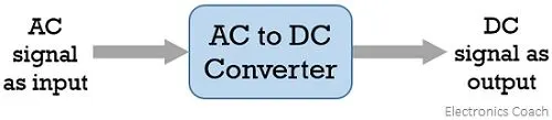
circuit diagram :
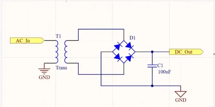
AC to DC Converter is further classified as:
- Diode Rectifiers:
- This rectifier circuit changes applied ac input voltage into a fixed dc voltage. Either a single-phase or three-phase ac signal is applied at the input.
- These are mainly used in electric traction and in electrochemical processes like electroplating along with in battery charging and power supply. These are also used in welding and UPS related services.
- Phase Controlled Rectifiers:
- Unlike diode rectifiers, phase-controlled rectifiers are designed to convert a fixed value of ac signal voltage into a variable dc voltage.
- Here line voltage operates the rectifier hence these are sometimes known as line commutated ac to dc converters. Similar to diode rectifiers, here also the applied ac signal can be a single-phase or three-phase ac signal.
- Its major applications are in dc drives, HVDC systems, compensators, metallurgical and chemical industries as well as in excitation systems for synchronous machines.
DC to DC Converters :
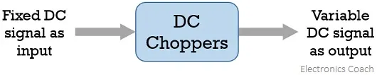
- The converters that convert the dc signal of fixed frequency present at the input into a variable dc signal at the output are also known as choppers.
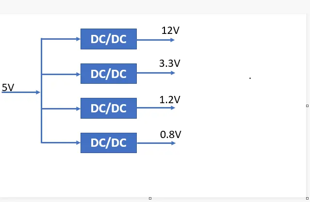
- Here the achieved output dc voltage may have a different amplitude than the source voltage. Generally, power transistors, MOSFETs, and thyristors are the semiconductor devices used for their fabrication.
- The output is controlled by a low power signal that controls these semiconductor devices from a control unit.
- Here forced commutation is required to turn off the semiconductor device. Generally, in low power circuits power transistors are used while in high power circuits thyristors are used.
- Choppers are classified on the basis of the type of commutation applied to them and on the basis of the direction of power flow.
- Some major uses of choppers are in dc drives, SMPS, subway cars, electric traction, trolley trucks, vehicles powered by battery, etc.
DC to AC Converters :
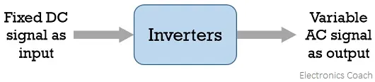
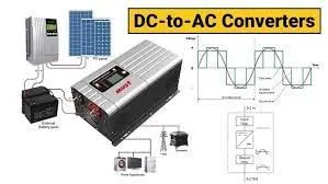
- The devices that are designed to convert the dc signal into ac signal are known as inverters.
- The applied input is a fixed dc voltage that can be obtained from batteries but the output obtained is variable ac voltage. The voltage and frequency of the signal obtained are of variable nature.
- Here the semiconductor device i.e., the thyristor is turned off by using either line, load, or forced commutation.
- Thus, it can be said that by the use of inverters, a fixed dc voltage is changed into an ac voltage of variable frequency. Generally, the semiconductor devices used for its fabrication are power transistors, MOSFETs, IGBT, GTO, thyristors, etc
refer :
https://sciencing.com/dc-ac-power-converter-work-5202726.html
- Inverters mainly find applications in induction motor and synchronous motor drives along with UPS, aircraft, and space power supplies.
- In high voltage dc transmission system, induction heating supplies as well as low power systems of mobile nature like flashlight discharge system in photography camera to very high power industrial system.
- Like choppers, in inverters also conventional thyristors are used in high power applications and power transistors are used in low power applications.
AC to AC Converters :
An ac to ac converter is designed to change the ac signal of fixed frequency into a variable ac output voltage.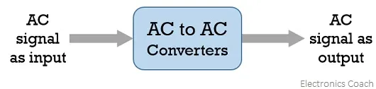
refer : https://www.elprocus.com/ac-to-ac-converter-working-and-supplies/
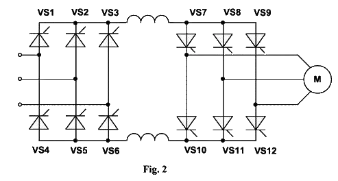
There are two classifications of ac to ac converters which are as follows:
- Cycloconverters:
- A cycloconverter is a device used for changing ac supply of fixed voltage and single frequency into an ac output voltage of variable voltage as well as different frequency.
- However, here the obtained variable ac signal frequency is lower than the frequency of the applied ac input signal. It adopts single-stage conversion.
- Generally, line commutation is mostly used in cycloconverters however forced or load commutated cycloconverters are also used in various applications.
- These mainly find applications in slow-speed large AC traction drives such as a rotary kiln, multi MW ac motor drives, etc.
- AC Voltage Controllers (AC voltage regulators):
- converters designed to change the applied ac signal of fixed voltage into a variable ac voltage signal of the same frequency as that of input.
- For the operation of these controllers, two thyristors in an antiparallel arrangement are used. Line commutation is used for turning off both the devices.
- It offers the controlling of the output voltage by changing the firing angle delay.
- The major applications of ac voltage controllers are in lighting control, electronic tap changers, speed control of large fans and pumps as well.
QUESTION 2
AIM : To find An Electric Vehicle's powertrain with 72V battery pack in shown in the diagram below. The duty ratio for acceleration operation is 'd1' and for the braking operation the duty ratio is 'd2'
Given data:-
voltage= 72 Volts
Rated armature current= 400 Amps
Ra= 0.5Ω, Motor constant = 0.7 Volt/sec
Chopper Switching frequency= 400 Hz
duty cycle =70%
Solution:
We have the formula
ouput volatge= battery volatge*duty cycle i.e = 72*0.7= 50.4 volts
so the vehicle voltage = 50.4 volts
Now taking the torque equation= Tv=Vv.kø/Ra-Kø^2/Ra.w_________ 1
now sub the given values in above equation 1
i.e Tv= 50.4*0.7/0.5-0.7^2/0.5*w
By sloving we get 70.56-0.97w^2
But in the question the vehicle speed torque characteristics is given as,
Tv=24.7-0.0051w^2________2
Now equating the above equations 1 and 2 we get
24.7-0.0051w^2 = 70.56-0.97w^2
0.0051w^2+0.97w-45.81=0
so now sustituting the above equations in quadratic equation formula
x = −b + √(b2 − 4ac)/2a = -0.97+-√ 0.97^2-4(0.0051)(-45.85)/2*(0.0051)
we get 39.19 rad/sec
Question:3
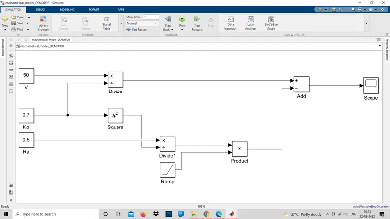
Aim: To Develop a mathematical model of a DC Motor for the below equation using Simulink.
ω">ωω= V/Kϕ">ϕϕ -Ra/Kϕ">ϕϕ^2 .T
Given data: V= 50 ,Kø=0.7,Ra= 0.5
simulink model of a dc motor :
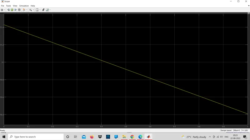
output :
question 4
AIM : Refer to the blog on below topic:
Induction Versus DC brushless motors by Wally Rippel, Tesla
- The above topic shows that the author ( wally rippel) describes about the induction vs brushless motors .
- In the intiall stage the author said that he was engineer at aerovironment wher he used to help develop the EV1 for general motors and he was featured in the documentary movie who killed the electric car and he also worked for the jet propulsion lab on Ev battery research.
- Intially the author explain about the ICE in automobile industry he said the in new coming generations the EV will play the key role in the auto mobile industry mainly he mentioned about the Dc brush less motor and induction motor.
- He thought that the brush motor should be replaced by the brush less motor or induction motor and he aslo thought that batteries should be replaced by the Litium-ion batteries
- He said that above mentiod motors and batteries are going to use in the future in Ev.Because the brushless and induction motor as some advantages wihich overcomes the problems in present ICE.
Brushless DC motor:
- The motor converts supplied electrical energy into mechanical energy.
- Various types of motors are in common use. Among all these Brushless DC motors (BLDC) feature high efficiency and excellent controllability and are widely used in many applications.
- The BLDC motor has power-saving advantages relative to other motor types.
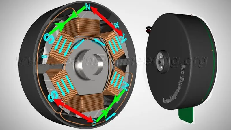
- We can expect to see the BLDC motors used in a wider range of applications in the future. For example they will probably be widely used to drive service robots small robots that deliver services in fields other than manufacturing.
Advantage of brush less motor:
The main advantages of a brushless motor over brushed motors are high power-to-weight ratio high speed nearly instantaneous control of speed (rpm) and torque high efficiency and low maintenance.
The author also said that the brushless dc motor prouduces zero starting torque which connected to fixed frequency.
Induction motor:
- The author said that the in future generation the induction motor drives a forerunner of the 3-phase induction motor motor was invented by Nikola tesla sometime before 1889.
- unlikely the stators for the 3-phase induction motor and the DC brushless motor are virtually identical.
- Both have three sets of distributed windings that are inserted within the stator core.
- The essential difference between the two machines is with the rotor.
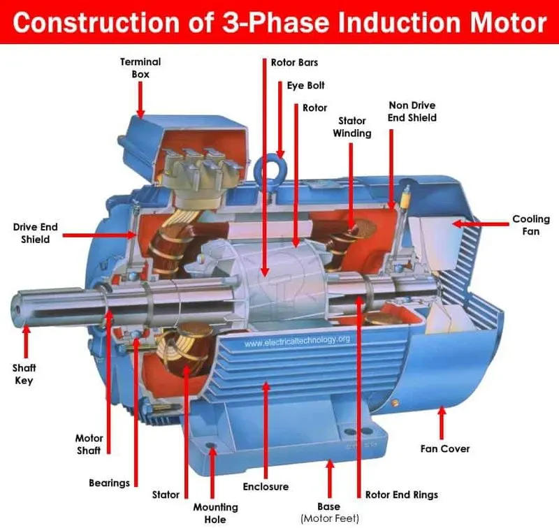
- An induction motor is also called as asynchronous motor is an ac motor in which the current in the rotor needed to produce torque is obtained by electromagentic induction from the magentic feild of the stator winding.
- An induction motor can be made without electrical connections to the rotor.
Advantage of Induction motor:
- It can be operated in harm conditions. Unlike synchronous motors a 3 phase induction motor has a high starting torque good speed regulation and reasonable overload capacity. the induction motor is a highly efficient machine with full load efficiency varying from 85 to 97 %
- And main disadvantage of the induction motor is The power factor of the motor is very low during light load conditions. During light load conditionsit operates at a very low power factor.
- From the total discussion the author said that brushless dc motor is going to play the key role in EV and aslo in HEV in upcoming days in automobile industry.
Conclusion:
We have succesfully completed the above required tasks
In case-1 we find the different types of power converters circuit used in electric and hybrid electric vehicle.
In case-2 we have find An Electric Vehicle's powertrain with 72V battery pack in shown in the diagram below. The duty ratio for acceleration operation is 'd1' and for the braking operation the duty ratio is 'd2'
In case-3 we have prepared the mathematical model for dc motor using matlab simulink
In case-4 we have refred the blog on Induction Versus DC brushless motors by Wally Rippel, Tesla