Week-6 Challenge: EV Drivetrain
Question 1:
Answer:
Different types of power converter circuits are
AC to DC Converter (Controlled Rectifier)
DC to DC Converter (DC Chopper)
AC to AC Converter (AC voltage regulator)
DC to AC Converter (Inverters)
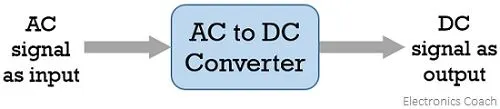
AC to DC Converter (Controlled Rectifiers)
A type of converter that changes input AC signal into a DC is known as AC to DC converter. We have already learned in basic electronics that the devices that convert the AC signal into DC signal are known as rectifiers
DC to DC Converter (DC Chopper)
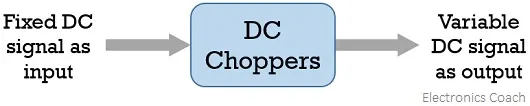
The converters that convert the dc signal of fixed frequency present at the input into a variable dc signal at the output are also known as choppers. Here the achieved output dc voltage may have a different amplitude than the source voltage. Generally, power transistors, MOSFETs, and thyristors are the semiconductor devices used for their fabrication. The output is controlled by a low power signal that controls these semiconductor devices from a control unit.Here forced commutation is required to turn off the semiconductor device. Generally, in low power circuits power transistors are used while in high power circuits thyristors are used.
DC to AC Converter (Inverters)
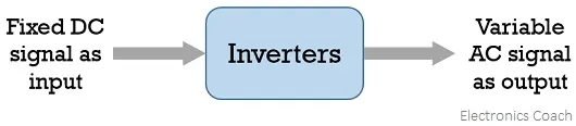
The devices that are designed to convert the dc signal into ac signal are known as inverters. The applied input is a fixed dc voltage that can be obtained from batteries but the output obtained is variable ac voltage. The voltage and frequency of the signal obtained are of variable nature. Here the semiconductor device i.e., the thyristor is turned off by using either line, load, or forced commutation.Thus, it can be said that by the use of inverters, a fixed dc voltage is changed into an ac voltage of variable frequency. Generally, the semiconductor devices used for its fabrication are power transistors, MOSFETs, IGBT, GTO, thriators etc.Inverters mainly find applications in induction motor and synchronous motor drives along with UPS, aircraft, and space power supplies. In high voltage dc transmission system, induction heating supplies as well as low power systems of mobile nature like flashlight discharge system in photography camera to very high power industrial system.Like choppers, in inverters also conventional thyristors are used in high power applications and power transistors are used in low power applications.
An ac to ac converter is designed to change the ac signal of fixed frequency into a variable ac output voltage.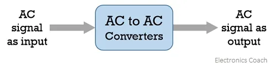
Cycloconverters: A cycloconverter is a device used for changing ac supply of fixed voltage and single frequency into an ac output voltage of variable voltage as well as different frequency. However, here the obtained variable ac signal frequency is lower than the frequency of the applied ac input signal. It adopts single-stage conversion. Generally, line commutation is mostly used in cycloconverters however forced or load commutated cycloconverters are also used in various applications.
These mainly find applications in slow-speed large AC traction drives such as a rotary kiln, multi MW ac motor drives, etc.
AC Voltage Controllers (AC voltage regulators): The converters designed to change the applied ac signal of fixed voltage into a variable ac voltage signal of the same frequency as that of input. For the operation of these controllers, two thyristors in an antiparallel arrangement are used. Line commutation is used for turning off both the devices. It offers the controlling of the output voltage by changing the firing angle delay.The major applications of ac voltage controllers are in lighting control, electronic tap changers, speed control of large fans and pumps as well.
Question 2:
Answer:
Given voltage=72v
armature resistance Ra=0.5
volt second kϕ=0.7
also Tv=24.7+0.0051w^2
T=Vkϕ/Ra-w*kϕ^2/Ra ------------- a
Sub value of Tv in equation a we get
24.7+0.0051w^2=100.8-0.98w-----------b
Dividing equation b by 0.0051 we get
w^2+192.1w=14921.5 ---------------------- c
solving equation c by
x = (-b ± √ (b² - 4ac) )/2a
w=
Question :3
Answer:Here the constant blocks are used to get armature resistance Ra Torque T voltage v and volt second kϕ
Each are obtained seperately and given to multilication block and the result is given to divide block then given to subtract block finaly the result obtained will be speed w.The variables are defined in work space using script .
Question 4:
Answer:In this blog the differences betweem brushless dc motor and induction motor is given
Both have different features and so its difficult to say whichone is better .The rotor includes two or more permanent magnets that generate a DC magnetic field (as seen from the vantage point of the rotor). In turn, this magnetic field enters the stator core (a core made up of thin, stacked laminations) and interacts with currents flowing within the windings to produce a torque interaction between the rotor and stator. As the rotor rotates, it is necessary that the magnitude and polarity of the stator currents be continuously varied – and in just the right way - such that the torque remains constant and the conversion of electrical to mechanical energy is optimally efficient.
Brushless dc motor is easy to control,its peak efficiency is high,it is suitable during low speed and high torque and during slow speed since the current and voltage is low the heating effect will also be low.Rotor cooling is easier and peak point efficiency is generally higher for this drive. The DC brushless drive can also operate at unity power factor.
Disadvantages of brushless dc motor
A brushless DC motor produces no starting torque when directly connected to fixed frequency utility power. They really need the aid of an inverter whose “phase” is maintained in step with the angular position of the rotor.With DC brushless, as machine size grows, the magnetic losses increase proportionately and part load efficiency drops. With induction, as machine size grows, losses do not necessarily grow. Also the permanent magnets are costly
Induction motor
Currents flowing in the stator windings produce a rotating magnetic field that enters the rotor. The frequency of this magnetic field as “seen” by the rotor is equal to the difference between the applied electrical frequency and the rotational “frequency” of the rotor itself. Accordingly, an induced voltage exists across the shorted structure that is proportionate to this speed difference between the rotor and electrical frequency. In response to this voltage, currents are produced within the rotor conductors that are approximately proportionate to the voltage, hence the speed difference. Finally, these currents interact with the original magnetic field to produce forces – a component of which is the desired rotor torque.The induction motor is used for high performance application.
Advantages
The motor has the ability to start under load. No inverter is needed. induction machines have no magnets and B fields are adjustable, since flux density is proportionate to V/f (voltage to frequency). This means that at light loads the inverter can reduce voltage such that magnetic losses are reduced and efficiency is maximized. Thus, the induction machine when operated with a smart inverter has an advantage over a DC brushless machine , magnetic and conduction losses can be controlled such that efficiency is optimized.
Disadvantage
Induction machines are more difficult to control.They cannot operate from DC. Shaft speed is proportionate to line frequency. Hence, when used with utility power, they are constant speed machines. Finally, when operated from utility power, they have limited starting torque and somewhat limited running peak torque capabilities, when compared to DC type machines.