Week-6 Challenge: EV Drivetrain
Which types of power converter circuits are employed in electric and hybrid electric vehicle?
Power electronics is one of the enabling technologies propelling the shift from conventional gasoline/diesel engine powered vehicles to electric, hybrid, and fuel cell vehicles
The converter acts as the link or the transforming stage between the power source and the power supply output. There are several kings of converters based on the source input voltage and the output voltage and these falls into four categories namely the AC to DC converter known as the rectifier, the AC to AC clycloconverter or frequency changer, the DC to DC voltage or current converter, and the DC to AC inverter.
Bi directional dc-dc converters.
Specific to these converters is that the energy flows in both directions of the converter. These converters are commonly used in various applications and they are connected between two levels of DC voltage, where energy is transferred from one level to another.
BUCK BOOST TYPE
The buck boost is a type of dc-dc converter that has an output voltage magnitude that is either greater than or less than the input voltage magnitude. It is equivalent to a flyback converter using a single inductor instead of a transformer.
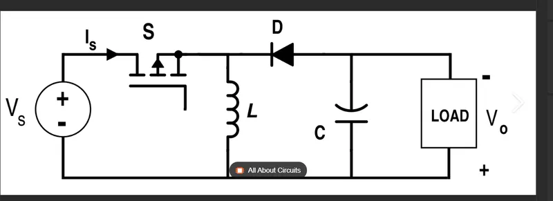
Two different topologies are called buck–boost converter. Both of them can produce a range of output voltages, ranging from much larger (in absolute magnitude) than the input voltage, down to almost zero
CUK CONVERTER
it is a type of buk boost convert but with low rippled currents
Similar to the boost buk converter with inverting topology, the output voltage of non-isolated Ćuk converter is typically inverted, with lower or higher values with respect to the input voltage
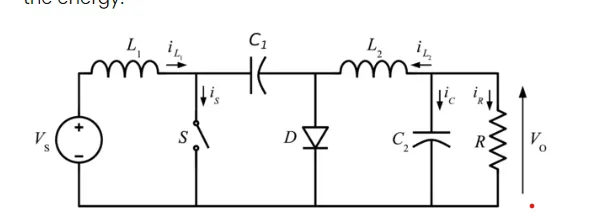
FULL BRIDGE CONVERTER.
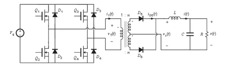
A Bridge Converter is a DC to DC converter topology (configuration) employing four active switching components in a bridge configuration across a power transformer. This has lower losses than a bridge rectifier.
A full bridge converter is one of the commonly used configurations that offer isolation in addition to stepping up or down the input voltage. Other functions may include reversing the polarity and providing multiple output voltages simultaneously.
2. An Electric Vehicle's powertrain with 72V battery pack in shown in the diagram below. The duty ratio for acceleration operation is 'd1' and for the braking operation the duty ratio is 'd2
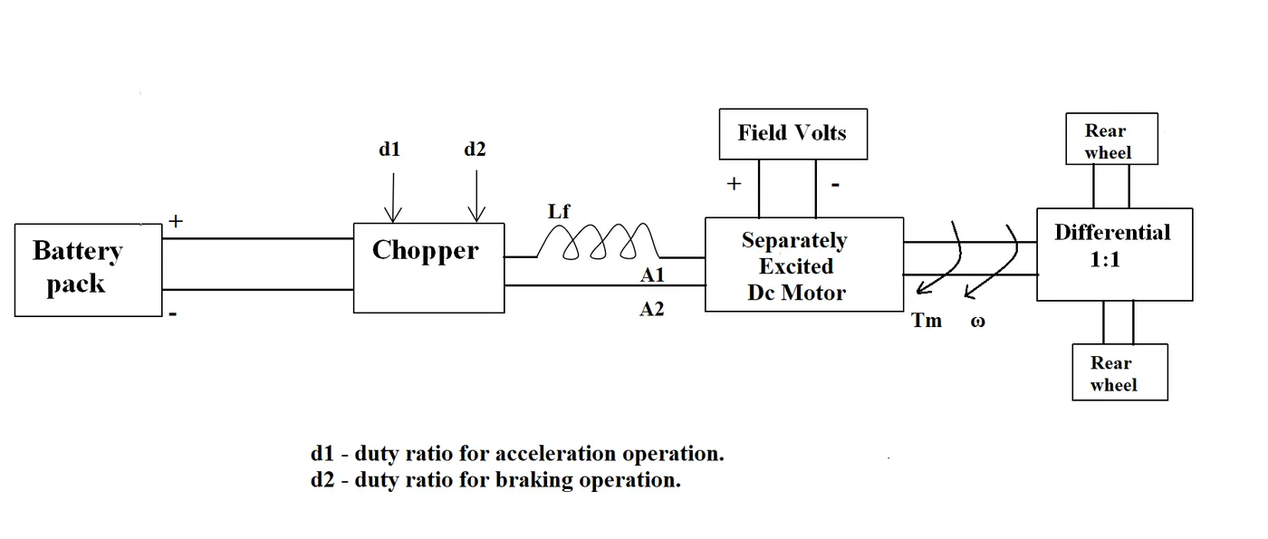
The other parameters of the electric vehicle is given below,
Motor and Controller Parameters:
Rated Armature voltage= 72 V
Rated armature current= 400 A
Ra= 0.5Ω, KΦ= 0.7 Volt second
Chopper Switching frequency= 400 Hz
The vehicle speed-torque characteristics are given by the below equation

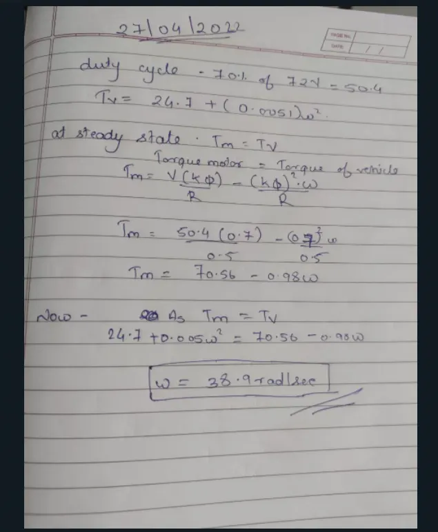
What is EV steady state speed if duty cycle is 70%?
3. Develop a mathematical model of a DC Motor for the below equation using Simulink.
ωω= V/Kϕϕ -Ra/Kϕϕ^2 .T
4)
4. Refer to the blog on below topic:
Induction Versus DC brushless motors by Wally Rippel, Tesla
Explain in brief about author’s perspective.
Both DC brushless and induction drives use motors having similar stators. Both drives use 3-phase modulating inverters. The only differences are the rotors and the inverter controls. And with digital controllers, the only control differences are with control code. (DC brushless drives require an absolute position sensor, while induction drives require only a speed sensor; these differences are relatively small.)
With brushless machines, the rotor includes two or more permanent magnets that generate a DC magnetic field (as seen from the vantage point of the rotor). In turn, this magnetic field enters the stator core (a core made up of thin, stacked laminations) and interacts with currents flowing within the windings to produce a torque interaction between the rotor and stator. As the rotor rotates, it is necessary that the magnitude and polarity of the stator currents be continuously varied – and in just the right way - such that the torque remains constant and the conversion of electrical to mechanical energy is optimally efficient. The device that provides this current control is called an iNVERTER Without it, brushless motors are useless motors.
Induction machines are more difficult to control. The control laws are more complex and difficult to understand. Achieving stability over the entire torque-speed range and over temperature is more difficult with induction than with DC brushless. This means added development costs, but likely little or no recurring costs.
One of the main differences is that much less rotor heat is generated with the DC brushless drive. Rotor cooling is easier and peak point efficiency is generally higher for this drive. The DC brushless drive can also operate at unity power factor, whereas the best power factor for the induction drive is about 85 percent. This means that the peak point energy efficiency for a DC brushless drive will typically be a few percentage points higher than for an induction drive.