Week-6 Challenge: EV Drivetrain
1) Which types of power converter circuits are employed in electric and hybrid electric vehicles?
* Four main power converter circuits are used in electric and hybrid electric vehicles.
* AC to DC converter:
This type of converter takes an AC power supply and converts it to a DC power supply.
Power generated from a power plant is transmitted to our homes at a voltage of 230V ata a frequency of 50HZ which we can use to power our electrical appliances, but our appliances operate on a DC supply and not on a AC supply, for this we can use converter for this application.
It has a n alternative waveform which repeatedly reverses direction.
In case of electric vehicles or hybrid electric vehicles, the battery which operates with a DC power supply is charged at home or a charging station where power is supplied in AC form from the electric grid.
So, chargers for these vehicles are a very easy example for AC to DC converter.
* DC to AC converter:
This type of converter takes DC supply and convetrts it to an AC power supply.
Power which is supplied from a bettery can have its form changed to AC type for use in homes.
Power generated by solar panels are stored in batteries in the form of DC form and this can power a house which uses an AC supply so wwe vcan utilise this power from the mains.
This type is referred to as an inverter and is widely usex in homes and in electric vehicles or hybrid electric vehicles.
* DC to DC converter:
This type is similar to a transformer in that it can change the voltage from its current level to another level.
It can take an input supply of voltage and increase it or do the exact oposite and decrease it similar to a step up or step down transformer.
This kind of converter is called as Chopper.
There are two types of DC to DC conveters:
** Isolated type
- Buck
- Boost
- Buck/Boost
- Cuk
- Charge Pump
** Non Isolated type
- Flyback converter
- Forward converter
* AC to AC converter:
This type of converter takes an input AC waveform with a particular voltage and frequency and outputs a different AC waveform with another voltage and frequency.
The output voltage or the frequency can be changed depending on the application.
There are four main AC to AC converters:
- Cycloconverters
- AC to AC convert with DC link
- Matrix converter
- Hybrid matrix converter
2) An Electric Vehicle's powertrain with 72V battery pack in shown in the diagram below. The duty ratio for acceleration operation is 'd1' and for the braking operation the duty ratio is 'd2'.
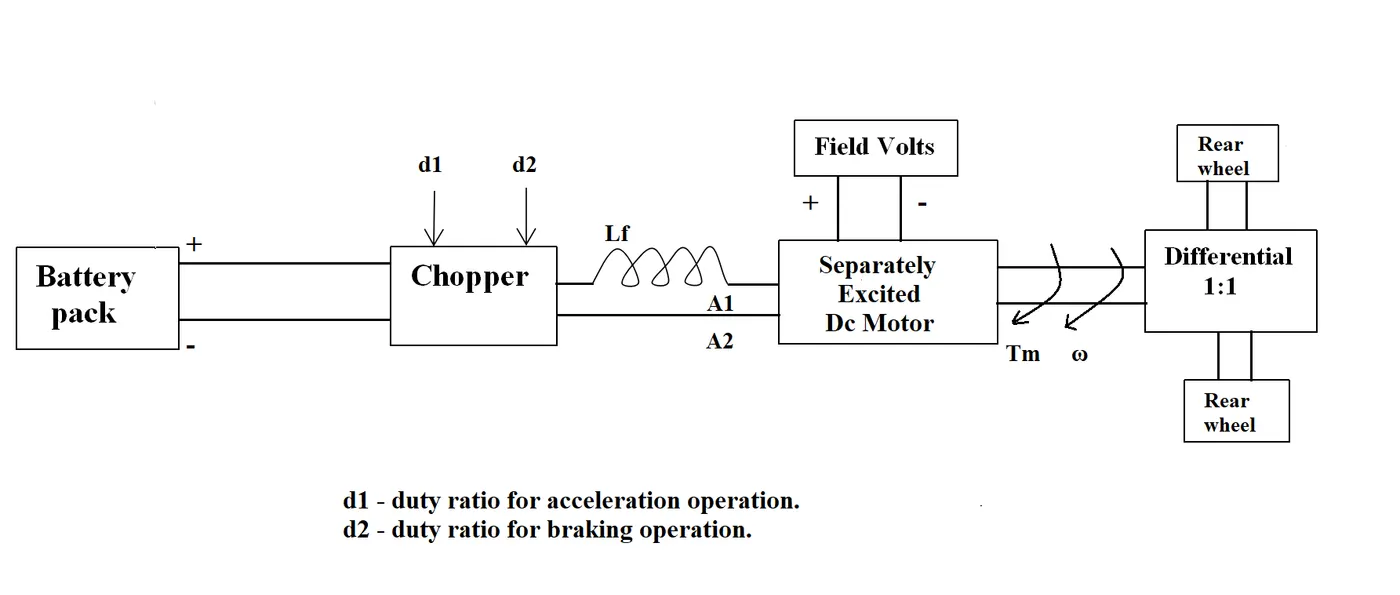
The other parameters of the electric vehicle is given below,
Motor and Controller Parameters:
Rated Armature voltage= 72 V
Rated armature current= 400 A
Ra= 0.5Ω, KΦ= 0.7 Volt second
Chopper Switching frequency= 400 Hz
The vehicle speed-torque characteristics are given by the below equation

What is EV steady state speed if duty cycle is 70%?
* We must find the speed in rad/sec and we can use the other expression given below,
T=((V*K)/R) - ((K^2)*W/R)
where,
T=torque
V=armature voltage
R=resistance
W=speed rad/sec
Now, we can compare the two equations or expressions,
24.7+0.0051*W^2 = ((V*K)/R) - ((K^2)*W/R)
24.7+0.0051*W^2 = (72*0.7*0.7)/0.5 - (0.7^2/0.5)*W
24.7+0.0051*W^2 = 70.56-0.98*W
W^2+192.15*W-8992.15=0
The above expression is similar to ax^2+bx+c.
and, therefore to find the roots we use the formula that we use to find the roots to the expression ax^2+bx+c.
** W = 38.95 rad/sec (speed value cannot be negative, so avoid the negative answer)
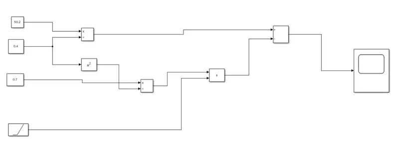
3) Develop a mathematical model of a DC Motor for the below equation using Simulink.
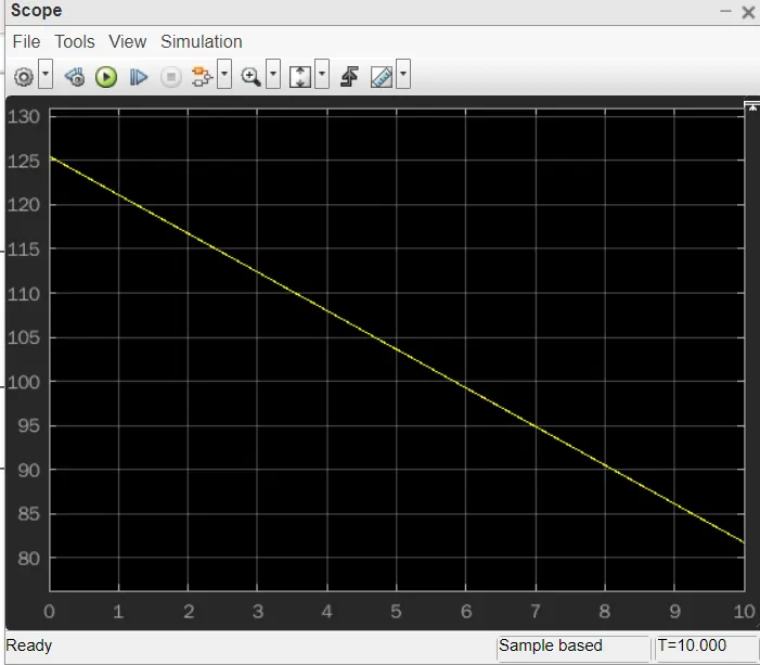
ω= V/Kϕ -Ra/Kϕ^2 .T
* Let us develop a mathematical model for the given expression using simulink:
let us consider,
V=50.2V
Kϕ=0.4
Ra=0.7
T=Torque as linearly increasing signal
* Simulink model:
* Graph or Result obtained:
4) Refer to the blog on below topic:
Induction Versus DC brushless motors by Wally Rippel, Tesla
Explain in brief about author’s perspective.
* The author writes this blog to show up the differences between the commonly used motor drives in the automobile industry, the Induction motor and the DC brushless motor.
Author Wally Rippel goes in to detail about the differences in the construction, cost between both of them etc...
In the ending of the first paragraph author writes 'there is no one best engine type' and this matters a lot while choosing an engine.
He also finishes the blog stating that ther is no winner among the two types.
From the blog we can understand that even both of the types are similar to each other they also have their very own drawbacks and benefits as well.
For the induction dirves, there rotor has no magnets but instead stacked steel laminations with buried peripheral conductors which form a shorted structure.
Induction motor can be used directly with power from the main and does not require an inverter to start the drive and generate the starting torque.
Induction motor drives cannot run on a DC power supply and are dependent on an AC power supply.
Dc brushless drive use permanent magnets and cannot change the strength of their magnitic filed.
When the torque required is minimum the magnetic field strength should also be minimum to reduce losses.
The induction drives do not have permanent magnest and so they can vary thier magnetic field strength.
CONCLUSION:
Finally Rippel has stated the differences between Induction dirves and the DC brushless drives.
He has also mentioned the advantages and disadvantages of both the types.
If one wants good performance with lesser cost then he can choose the Induction motor dirve.
If one wants high power factor easy control then he can choose the DC brushless drive.
The author believes that to the increasing performance of the vehicles one fine day bothe of them can be used together within the hood of a vehicle.
This can resukts in a new and a trendy kind of vehicle that combines the characteristics of both the drives.