Week-6 Challenge: EV Drivetrain
1) Which types of power converter circuits are employed in electric and hybrid electric vehicle?
Electric vehicles have low running costs as they have less moving parts for maintaining and also very environmentally friendly as they use little or no fossil fuels (petrol or diesel). While some EVs used lead acid or nickel metal hydride batteries, the standard for modern battery electric vehicles is now considered to be lithium ion batteries as they have a greater longevity and are excellent at retaining energy, with a self discharge rate of just 5% per month. Despite this improved efficiency, there are still challenges with these batteries as they can experience thermal runaway, which have, for example, caused fires or explosions in the Tesla model S, although efforts have been made to improve the safety of these batteries.
Power electronic systems form the heart and soul of the transportation electrification field. A basic understanding of the operation of power electronic systems is critical and involves gaining a basic knowledge of the switched-mode power converters [3]. The other aspects that need to be looked into, especially in DC-DC converters, include the steady-state operation, analysis, and simulation of the circuits. From the hardware perspective, a good understanding of the power semiconductor switching devices like diodes and switches like IGBTs or MOSFETs is essential. The system modeling has to account for the estimation of losses and efficiency.
DC-DC power converters can be employed to interface the elements in the electric powertrain by boosting or chopping the voltage levels. AC-DC converters are commonly used in PHEVs. A full-bridge DC-DC converter is the most commonly used circuit configuration for power conditioning, especially when electrical isolation is essential. The power converter comprises several components such as power semiconductor switches, gate drivers, cooling systems, inductors, capacitors, transformers, sensors, control boards, mechanical housing, etc. They are integrated and interact with each other to achieve electrical power conversion effectively, efficiently, and reliably. A sample power converter structure is illustrated in Figure 1 [2]. It is important to note that the functionality, volume, and cost of these components affect the characteristics and performance of the power converter.
the following are parts of power electronics used in electric vehicle as well as hybrid electric vehicle:-
1) AC- DC convertor (transformer,MOSFET,Bridge rectifier).
2) buck and boost convertor.
3) invertor.
4) DC-DC convertor.
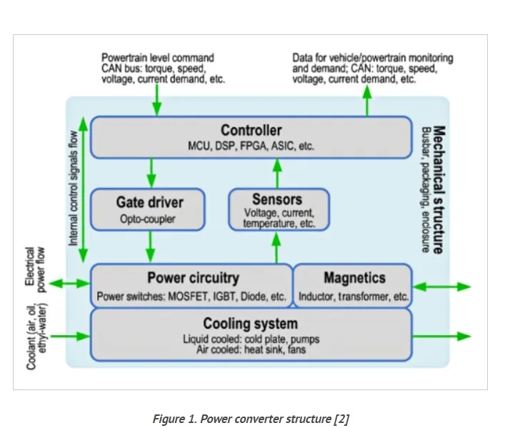
The power semiconductor switches used in automotive applications are mostly IGBTs for systems rated between 200 and 1200 V, and MOSFETs for converters rated at lower voltage like 12 or 48 V. In the last decade, wide-bandgap devices based on silicon carbide (SiC) or gallium nitrate (GaN) have been developed to enhance the performance of power converters. Compared to the conventional silicon-based power switches, the SiC-based devices offer improved switching characteristics, higher voltage operation, and better thermal properties. This translates into lower switching losses and higher thermal conductivity, which in turn reduces the cooling requirements.
The passive components used in a power converter mainly consist of capacitors and magnetic components. Capacitors improve the power quality of the converter by filtering the input and output currents and prevent the ripple component from entering the battery. The passive magnetic components include the power inductors, high-frequency transformers, and chokes or EMI filters. Power inductors are primarily employed in boost converters and battery chargers, whereas high-frequency transformers are used in auxiliary power converters. The design of the magnetic component and the core material govern the size and efficiency of the overall converter.
The cooling system is another critical component that helps with the reliability and power density aspects of the power converter. It prevents the components from operating at a harmful temperature. The heat generated by the losses incurred from the power switches and passive components needs to be evacuated from the module or the component first and then from the power converter. To enable higher power density and overcome possible issues during such a process, cooling is essential. For low-power applications, forced air cooling can be used. For high-power applications, liquid cooling is preferred due to its heat dissipation capability, and it can be used in traction inverters. The cooling performance of the switches can be enhanced by integrating as many features as possible in the power modules.
2)
An Electric Vehicle's powertrain with 72V battery pack in shown in the diagram below. The duty ratio for acceleration operation is 'd1' and for the braking operation the duty ratio is 'd2'.
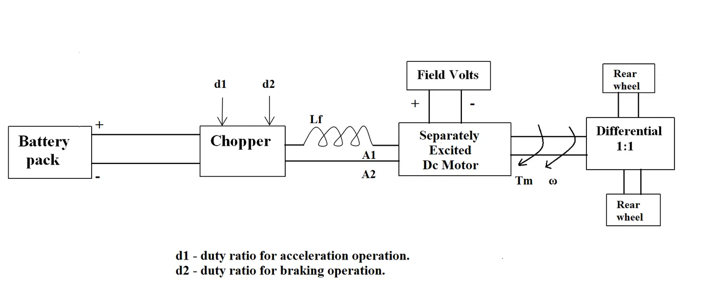
the other parameters of the electric vehicle is given below:
motor and controller parameters:
Rated Armature voltage = 72 v.
Rated Armature current = 400A.
Ra = 0.5 ohm
K = o.7 volt second
Chopper Switching Frequency = 400 Hz
The vehicle speed torque char are given by the given equation:-
Tv = 24.7 + (0.0051)w^2
Duty cycle = 70 %.
Solution:-
Vehicle output voltage (Vv) is givenby:-
Vv = battery Voltage (v) * Duty Cycle.
Vv = 72 * 0.70
Thus, Vehicle Voltage = 50.4 V.
Now, equation for vehicle torque is given by:-
Ts= (Vs- w.Ks).K / Ra
Where;
Tv = vehicle Torque (N-m)
Vv = Vehicle voltage (volts)
W = steady state speed of vehicle(rps)
K = Motor constant
Ra = Armature Resistance
Substituting all these values in equation, we get:
Tv = (50.04 - 0.7 * w) * 0.7 / 0.5
Tv= 70.56 - 0.98*w
Tv = 24.7 + 0.0051.w^2
Solving these two equations,
70.56 - 0.98*w = 24.7 + 0.0051* w^2
We get a Quadratic equation:
0.0051 * w^2 + 0.98 * w - 46.94 = 0
Since quadratic equation we get two values of :
w= 38.85 rad/s and w = -230.95 rad/s
we take the positive value:
Steady state speed of vehicle = 38.95 rad/s.
3) Develop a mathematical model of a DC Motor for the below equation using Simulink.
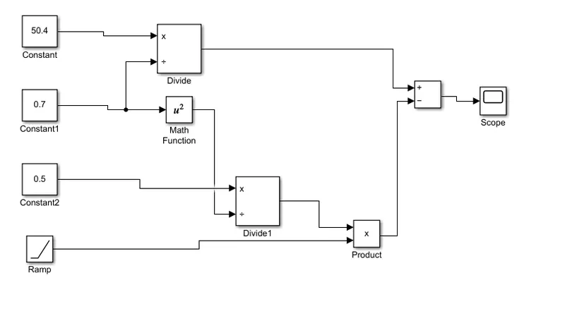
ωω= V/Kϕϕ -Ra/Kϕϕ^2 .T
Here the equation is presented in the form of the simulink model and following are blocks used for making model:-
1) constant.
2) ramp signal block.
3) arithmetic function block
4) math function
5) scope.
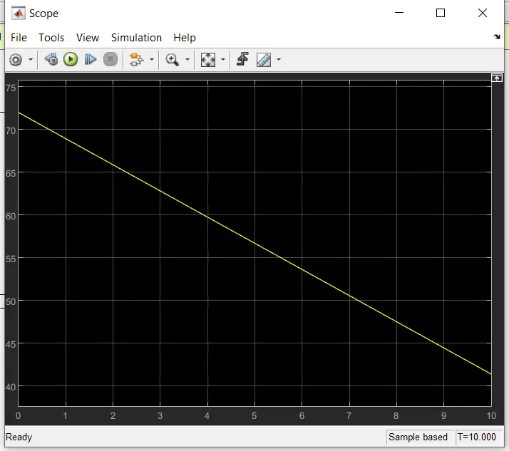
this is a speed torque char of dc motor, it shows the starting torque is 71 Nm, torque becomes zero when speed 70.5.
Google drive link:- https://drive.google.com/file/d/1U90xbNzL3oxsx0JPv0-WxQse6DCxq8wS/view?usp=sharing
4)
Refer to the blog on below topic:
Induction Versus DC brushless motors by Wally Rippel, Tesla
Explain in brief about author’s perspective.
wally ripple first explain working of bldc motor and ac induction motor.
Brushless DC motor, the rotor includes two or more permanent magnets that gernerate a DC magnetic field. In turn, this magnetic field enters the stator core and interacts with current flowing within the winding to produce a torque interaction between the rotor and stator. As the rotor rotates, it is necessary that the magnitude and polarity of the statpr currents be continuosly varied and in just the right way such that the torque remains constant and the conversion of electrical to mechanical energy is optimally efficient.
The device that provides this current control is calledd an inverter and without it brushless motors are useless motors.
Indusction motors has stator winding, but its rotot does not have permanent magnets like dc motors, rotors conatain laminated steels stacks, its a self starting motor, does not require inverter for starting. In constrast, a brushless dc motor producesno starting torque when directly connected to fiexed frequency utility power. They have limited starting torque and somewhat limited running peak torque capabilities, when compared to DC type machine.
DC brushless drives requires an absolute position sensor, while induction drives require only a speed sensor, there differences are relatively small brushless drive, the strenght of the magnetic filed produces by the permanent magnets would be adjustable.with DC brushless, as machine size grows, the magnetic losses increase proportionately and part load efficiency drops nad with induction size grows, losses do not necessarily grow.
his conclusion is that dc brushless drives will likely continue to dominate in the hybrid and coming plug-in hybrid markets and that induction drives will likely maintain dominance for the high performanance pure electric. The hardware is common for both drives could mean that we will see induction and dc brushless live and work side by side during the coming golden era of hybrid and electric vehicles.