Week-6 Challenge: EV Drivetrain
1. Which types of power converter circuits are employed in electric and hybrid electric vehicle?
Power electronics
Definition: A study that utilizes electronic power devices from converting one form of electric power into another form of electric power with proper control is known as Power Electronics. Basically, in power electronics, solid-state electronics, is used that performs the action of control and convert of the electric power.
Power Electronics is regarded as an important subfield of electrical and electronics engineering.
The pictorial representation given below provides an idea about the operation of a power electronics-based system: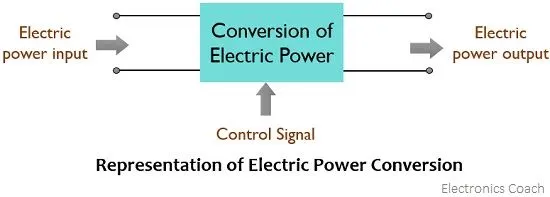
A power converter is an electrical circuit that changes the electric energy from one form into the desired form optimized for the specific load. A converter may do one or more functions and give an output that differs from the input. It is used to increase or decrease the magnitude of the input voltage, invert polarity, or produce several output voltages of either the same polarity with the input, different polarity, or mixed polarities such as in the computer power supply unit.
In a hybrid and other electric vehicles (EVs), two key elements work together to manage power and recharge the circuits. Here is how these critical components—the inverter and converter—work in tandem.
Broadly speaking, an inverter is an electrical device that converts electricity derived from a DC (Direct Current) source to AC (Alternating Current) of the type that can be used to drive a device or appliance. In a solar power system, for example, the power stored by batteries charged by solar panels is converted to standard AC power by the inverter,1 which provides the power to plug-in outlets and other standard 120-volt devices.
An inverter serves the same kind of function in a hybrid or EV car, and the theory of operation is relatively simple.2 DC power, from a hybrid battery, for example, is fed to the primary winding in a transformer within the inverter housing. Through an electronic switch (generally a set of semiconductor transistors), the direction of the flow of current is continuously and regularly flip-flopped (the electrical charge travels into the primary winding, then abruptly reverses and flows back out). The in/outflow of electricity produces AC current in the transformer's secondary winding circuit. Ultimately, this induced alternating current electricity provides power for an AC load—for example, an electric vehicle's (EV) electric traction motor.
A rectifier is a similar device to an inverter except that it does the opposite, converting AC power to DC power.
More properly called a voltage converter, this electrical device actually changes the voltage (either AC or DC) of an electrical power source.2 There are two types of voltage converters: step up converters (which increases voltage) and step down converters (which decreases voltage). The most common use of a converter is to take a relatively low voltage source and step-it-up to high voltage for heavy-duty work in a high power consumption load, but they can also be used in reverse to reduce voltage for a light load source.
The main devices of power electronics devices required in an electric vehicle are:-
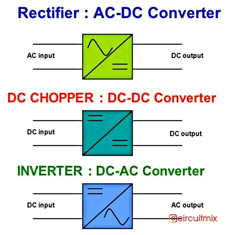
1. Rectifiers: The rectifiers are used in AC-DC conversion stages of Plug in EVs(PEV) where the grid electricity is firstly met with this device. The grid voltage obtained from the plug is 110V/60Hz or 220V/50Hz single-phase ac input in household application of PEV. Rectifiers are analysed in ideal circuit topology and uncontrolled or controlled power switch topologies.
2. Power Converters: Power converters are classified according to their input and output types namely DC-DC Converters and AC-AC Cycloconverters. DC-DC Converters are designed to increase or decrease the input voltage stage to desired value at the output. Therefore, a device known as Buck Converter or step-down converter decreases the output value according to a high input voltage while Boost Converter or step-up converter generates an increased output voltage. The cycloconverters are used to convert input power at one frequency to output power at a different frequency. This can also be achieved by inverter.
Besides the unidirectional dc-dc converters, Bidirectional Converter Topologies are also being used. When the EV driver switched into braking mode the batteries are charged by electric motor owing to bidirectional structure of converter. Therefore, the bidirectional dc-dc converter will be the key device in EVs.
3. Controller and Sensors: Almost all the power electronics in PEV require control signals as met in industrial applications. Conventional linear control such as PID controller can no longer satisfy the stringent requirements placed on high-performance EV’s. The required control signals are generated by Microcontrollers and commutate power electronic devices with switches to provide fixed speed or torque. Pulse Width Modulation technique is adopted by controllers To obtain the instant control action, interface electronic devices are used besides Current and Voltage sensors located in the related parts.
4. Inverters: In EVs, Inverters are used for DC-AC conversions. They are used to provide the required AC voltage and/or current for ac motors from DC battery supply, and consequently, the inverter control algorithms perform motor control operations in terms of torque and speed. Inverters are considered as voltage source inverters (VSI) and current source inverters (CSI) according to the type of output generation where VSIs are widely used in many industrial applications.
The Latest Power Electronics in EV propulsion is used in the form of a Resonant DC-link Inverter for ac motor driving operations. These resonant dc-link inverters have either a parallel or series resonant circuit, thus providing either zero-voltage-switching (ZVS) or zero-currentswitching (ZCS) condition. It facilitates the inverter to operate in soft-switching mode to decrease the switching losses and to increase the efficiency. The auxiliary circuit helps enable the load to be swung to the opposite rail to assure zero turnon voltage. If the auxiliary circuit is not included, then it is very difficult to ensure zero turn-on voltage due to load current constraints.
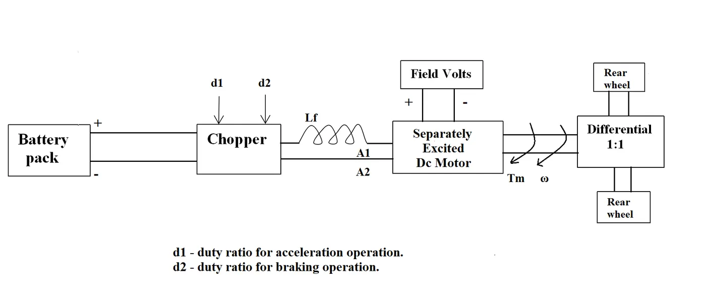
2. An Electric Vehicle's powertrain with 72V battery pack in shown in the diagram below. The duty ratio for acceleration operation is 'd1' and for the braking operation the duty ratio is 'd2'.
The other parameters of the electric vehicle is given below,
Motor and Controller Parameters:
Rated Armature voltage= 72 V
Rated armature current= 400 A
Ra= 0.5Ω, KΦ= 0.7 Volt second
Chopper Switching frequency= 400 Hz
The vehicle speed-torque characteristics are given by the below equation

What is EV steady state speed if duty cycle is 70%(0.7)?
solution-
the average volatge is given by the product of the battery voltagge and the duty cycle
Vs= V × dc
Vs = 72 × 0.7
Vs = 50.4
the Average voltage is 50.4 V ,
The vehicle speed-torque characteristics are given by the below equation
-----------------------------eq1
the derived formula for the motor speed characteristics.-
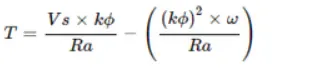
by substituting the given values in above formula- we get
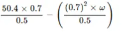
T= 70.56- 0.98.W-----------------------------eq2
by comparing equation 1and 2
70.56-0.98.w=24.7+(0.0051).w^2
0.0051w^2+ 0.98w-45.86=0
By using quadratic equation formula we get

as the speed value cannot be negative
w= 38.92 rad/s.
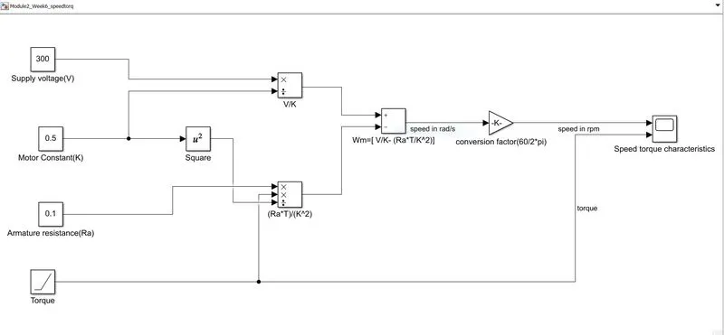
3. Develop a mathematical model of a DC Motor for the below equation using Simulink.
ω= V/Kϕ -Ra/Kϕ^2 .T
4. Refer to the blog on below topic:
Induction Versus DC brushless motors by Wally Rippel, Tesla
Explain in brief about author’s perspective.
the author;s provide very excellent information about difference and uses between induction motor and brushless dc motor. according to them DC brushless drives will likely continue to dominate in the hybrid and coming plug-in hybrid markets, and that induction drives will likely maintain dominance for the high-performance pure electrics. The question is what will happen as hybrids become more electrically intensive and as their performance levels increase? The fact that so much of the hardware is common for both drives could mean that we will see induction and DC brushless live and work side by side during the coming golden era of hybrid and electric vehicles.
difference between induction motor and Brushless dc motor -accorging to wally rippel
there is a difference between brushless and induction motor is the control.The dc brushless require a position sensor but an induction motor requires only a speed sensor .
Less rotor heat is generated in dc brushless drive and rotor cooling is easier and peak point efficiency is generally higher in induction drive.
Both DC brushless and induction drives use motors having similar stators. Both drives use 3-phase modulating inverters. The only differences are the rotors and the inverter controls. And with digital controllers, the only control differences are with control code. (DC brushless drives require an absolute position sensor, while induction drives require only a speed sensor; these differences are relatively small.
One of the main differences is that much less rotor heat is generated with the DC brushless drive. Rotor cooling is easier and peak point efficiency is generally higher for this drive. The DC brushless drive can also operate at unity power factor, whereas the best power factor for the induction drive is about 85 percent. This means that the peak point energy efficiency for a DC brushless drive will typically be a few percentage points higher than for an induction drive.
In contrast, induction machines have no magnets and B fields are “adjustable,” since B is proportionate to V/f (voltage to frequency). This means that at light loads the inverter can reduce voltage such that magnetic losses are reduced and efficiency is maximized. Thus, the induction machine when operated with a smart inverter has an advantage over a DC brushless machine – magnetic and conduction losses can be traded such that efficiency is optimized. This advantage becomes increasingly important as performance is increased. With DC brushless, as machine size grows, the magnetic losses increase proportionately and part load efficiency drops. With induction, as machine size grows, losses do not necessarily grow. Thus, induction drives may be the favored approach where high-performance is desired; peak efficiency will be a little less than with DC brushless, but average efficiency may actually be better.
Induction machines are more difficult to control. The control laws are more complex and difficult to understand. Achieving stability over the entire torque-speed range and over temperature is more difficult with induction than with DC brushless. This means added development costs, but likely little or no recurring costs.