Week-6 Challenge: EV Drivetrain
AIM:
- To study about types of power converters used in the EV and HEV Vehicles.
- To find out Steady state speed for an Electric Vehicles Powertrain.
- Develop mathematical model for the DC motor by using the equation `omega=(V)/(Kϕ )-(Ra)/(Kϕ^2 ) *T`
- To find differences in Induction motor and Dc Brushless motor using author's perpesctive.
OBJECTIVE:
- To indentify the types of power converter circuits emplyoyed in electric and hybrid electric vehicle.
- To calculate the steady state speed of an EV with given inputs if duty cycle s 70%.
- To create mathematical model for the DC motor by using the equation `omega=(V)/(Kϕ )-(Ra)/(Kϕ^2 ) *T`.
- Refer the below blog on given topic:
Induction Versus DC brushless motors by Wally Rippel,Tesla, Explain in brief about author’s perspective.
STUDY 1: Power convereter circuits used in the EV and HEV vehicles.
POWER ELECTRONIC CONVERTERS:
- Power elecronic converters are used everywhere in normal daily routines at home,commercial workplaces or in an industrial environment.Due to the high power handling with higher efficiencies.These converters become an integral part of industrial electric drives,high electric [power supplies,electric traction systems and automobile control equipments.
- Power electronics technology also deals with processing and controlling the flow of electrical energy in order to supply voltages and currents is a form that optimally suited for end user's requirements.
- a power electronic converter uses power electronic components such as SCR's,TRIAC's,IGBT's,etc.to control and convert the electric power.The main aim of the converter is to produce conditioning power with respect to a certain application.
- Thw block diagram of a power converter is shown below figure.It consist of an electrical energy source,power electronic circuit,control circuit and an electrical load.This converetr changes energy from one form of electrical energy to other from of electrical energy.
- The power electronic circuit consist of both part power circuit and control circuit.Power circuit transfers energy rom source to load and it consist of power electronics switches like SCR or TRIAC,transformers,electric choke,capaciotors,fuses and sometime resistors too.
- The control circuit or block regulate the elements in the power part of the converter.This block is built with a complex low power electronic circuit that consist of either analog or digital circuit assembly.
- Power electronic converters perform various basic power conversion functions.This converter is a single power conversion stage that can perform any of the functions in AC and DC power conversion systems.
Power converter Circuit for EV and HEV:
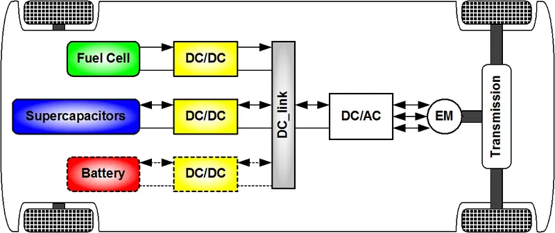
Non-isolated converters
- The non-isolated converters type is generally used where the voltage needs to be stepped up or down by a relatively small ratio (less than 4:1). And when there is no problem with the output and input having no dielectric isolation. There are five main types of converter in this non-isolated group, usually called the buck, boost, buck-boost, Cuk and charge-pump converters. The buck converter is used for voltage step-down, while the boost converter is used for voltage step-up. The buck-boost and Cuk converters can be used for either step-down or step-up. The charge-pump converter is used for either voltage step-up or voltage inversion, but only in relatively low power applications.
Isolated converters
- Usually, in this type of converters a high frequency transformer is used. In the applications where the output needs to be completely isolated from the input, an isolated converter is necessary. There are many types of converters in this group such as Half-Bridge, Full-Bridge, Fly-back, Forward and Push-Pull DC/DC converter. All of these converters can be used as bi-directional converters and the ratio of stepping down or stepping up the voltage is high.
Types of power converter circuits:
a. AC to DC Converters or Rectifiers:
- The task of turning alternating current into direct current is called rectification, and the electronic circuit that does the job is called a rectifier. The most common way to convert alternating current into direct current is to use one or more diodes, those handy electronic components that allow current to pass in one direction but not the other.
- Although a rectifier converts alternating current to direct current, the resulting direct current isn't a steady voltage. It would be more accurate to refer to it as "pulsating DC: Although the pulsating DC current always moves in the same direction, the voltage level has a distinct ripple to it, rising and falling a bit in sync with the waveform of the AC voltage that's fed into the rectifier. This converter circuit can be observed in EV charger.
- There are three distinct types of rectifier circuits as follows,
- Half wave rectifier: The simplest type of rectifier is made from a single diode. This type of rectifier is called a half-wave rectifier because it passes just half of the AC input voltage to the output.
- Full-wave rectifier: A full-wave rectifier uses two diodes, which enables it to pass both the positive and the negative side of the alternating current input. The diodes are connected to the transformer.
- Bridge rectifier: The problem with a full-wave rectifier is that it requires a centre-tapped transformer, so it produces DC that's just half of the total output voltage of the transformer.
b. DC to DC converter:
- A DC-to-DC converter is an electronic circuit or electromechanical device that converts a source of direct current (DC) from one voltage level to another. It is a type of electric power converter. Power levels range from very low (small batteries) to very high (high-voltage power transmission).
- DC/DC converters can be designed to transfer power in only one direction, from the input to the output. However, almost all DC/DC converter topologies can be made bi-directional. A bi-directional converter can move power in either direction, which is useful in applications requiring regenerative braking.
Used in auxiliay of Electric vehicles.
c. AC to AC converters:
- AC to AC converters is used for converting the AC waveforms with one particular frequency and magnitude to AC waveform with another frequency at another magnitude. This conversion is mainly required in case of speed controlling of machines, for low frequency and variable voltage magnitude applications as well.
d. DC to AC converters or Inverters:
- DC to AC converters is mainly designed for changing a DC power supply to an AC power supply. Here, DC power supply is comparatively stable as well as positive voltage source whereas AC oscillates approximately a OV base stage, typically in a sinusoidal or square or mode. The common inverter technology used in electronics is to convert a voltage source from a battery into an AC signal. Generally, they operate with 12 volts and commonly used in applications like automotive, lead-acid technology, photovoltaic cells, etc.
STUDY 2:
TO FIND STEADY-STATE SPEED IF DUTY CYCLE IS 70% -
Given:
Rated Armature voltage=72V
Rated armature current=400A
Ra=0.5Ω, `Kphi=0.7`Volt Second
Chopper switching frequency=400Hz
Actual voltage=0.7*72=50.4V
Solution:-
Speed-Torque equation of motor,
`omega=(V)/(K*phi)-(R_a/(K*phi))^2*T_m`
`T_a=((V*K*phi)/(R_a)-(K*phi)^2/R_a)omega`
`omega`=Steady state speed of the vehicle.
V=actual voltage
`T_v`=Vehicle torque
`K*phi`=Motor Constant
`R_a=`Armature Resistance
`T_v=((50.4*0.7)/0.5-(0.7)^2/0.5)*omega`
w.r.t
`omega=-b+-sqrt(b^2-4*a*c)/(2*a)`
`omega=-0.98+-sqrt((0.98^2+(4*0.0051*45.86))/(2*0.0051)`
`omega=-231.071`rad/sec
`omega=38.914`rad/sec`
STUDY 3:
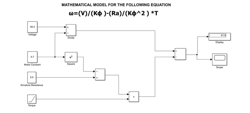
Rated armature Voltage=50.4V
Ra=0.5O Ohm
`K*phi`=0.7 Volt Second
Torque was increased from 0 to 10 in 10 Sec
Output:
The simulation is run for 10 seconds and the following output was obtained.
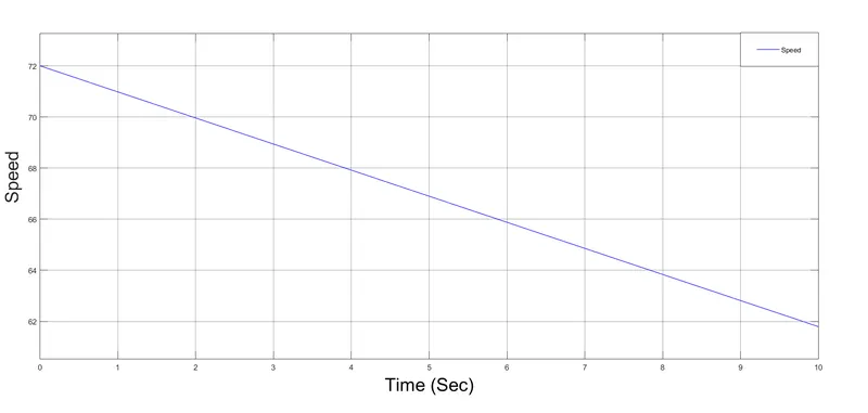
In the above snapshot we can see that with increase in torque the speed decreases.
STUDY 4:
- According to the blog ' Induction versus DC Brushless motors by Wally Rippel,Tesla', the author wants to highlight topics related to EV technology,especially related to DC brushes and motors.
- According to author's DC (direct current) is replaced by DC Brushless motors or by Induction motors.Also lead-acid battery is replaced by lithium-ion batteries for EV's.He said that there will be the future of both the components inuction and brushless DC motors depends upon their demands and uses.
DC Brushless motor:
- The technology behind the DC brushless motor is that it has more than 2 permanent magnet which generates a DC magnetic field.For better torque generation in rotor and stator,a current flow in winding and this happen due to magnetic field near the stator.According to him, the brushless motor needs a proper flow of current into stator and rotor if it will not in proper way then the current will not generate and there will be decrease in the torque.To maintain the electrical to mechanical converson there should be smooth flow of current otherwise this brushless motor is not useful.A Brushless motor doesn't create any starting torque.
- The advantage of a DC brushless motor is that there is low heat generation in the rotor,its cooling capacity is better as compared to inducton motor drive,also peak power efficiency is high .Another difference is that the DC Brushless drive can also operate at unity power factor.Whereas the best power factor for the induction drive is about 85%.This means that the peak point energy efficiency for a DC Brushless drive will typically be a few percentage pouints that for an induction drive.
Induction motor:
- The technology behind the induction motor is that it basically uses a `3phi`induction motor which was discovered by Nicola Tesla in 1889.In induction motor there is the use of the steel laminated device instead of magnets.Current flowing in the stator windings produce a rotatting magnetic field that enetrs the rotor.In an Induction motor current interact with the magnetic field to produce a force which is required for rotor torque.The Induction motor is compatible with any power sourcs.An induction motor can't operate operate from DC voltage it always require AC voltage.
- The Induction Motor doesn't have any magnets and in this B fileld is adjustable.in an Induction Motor B field is proportionate to `V/f` (Voltage to frequency0.This technology is used to reduce the magnetic losses and the overall efficiency will be increased.In an Induction Motor has many advantages that it does not have any magnetic losses and conduction losses,due to which efficiency will maintain at maximum peak.This all lead to increasing the performance,induction motor is very useful and efficient for high performance.In an induction motor,the peak efficiency is less but it works smoothy better.The controlling of Induction motor or mechanism is mre complex.also the torque generation is low the motor temperature incrases when it works at high speed.
CONCLUSION:
- We have discussed about the different types of power converter circuits employed in electric and hybrid electric vehicles.
- The EV steady state speed of an EV drivetrain was found out with the given input values.
- We have studied a blog on the topic Induction Versus DC Brushless motors by Wally Rippel,Tesla and explained about the author's perspective.