Week-6 Challenge: EV Drivetrain
Q1. Which types of power converter circuits are employed in electric and hybrid electric vehicle?
Power Converter:
- Power electronics is the application to the control and conversion of electric power.
- A power converter is a process of converting electric energy from one form to another.
- A power converter is an electro-mechanical device for converting electrical energy.
- A power converter can convert alternating current (AC) into direct current (DC) and vice versa; change the voltage or frequency of the current or do some combination of these.
- There are three types of Power converter circuits used in EV's and HEV's are given below:
- AC to DC (Rectifier)
- DC to AC (Inverter)
- DC to DC
- AC to DC (Rectifier):
A rectifier is an electrical device that converts alternating current (AC), which periodically reverses direction, to direct current (DC), which flows in only one direction. The process is known as rectification since it "straightens" the direction of the current.
- DC to AC (Inverter):
- An inverter is a device that converts DC power to the AC power used in an electric vehicle motor.
- The inverter can change the speed at which the motor rotates by adjusting the frequency of the alternating current.
- It can also increase or decrease the power or torque of the motor by adjusting the amplitude of the signal.
- The resulting AC frequency obtained depends on the particular device employed. Inverters do the opposite of "converters" which were originally large electromechanical devices converting AC to DC.
- The input voltage, output voltage and frequency, and overall power handling depend on the design of the specific device.
- The inverter does not produce any power; the power is provided by the DC source.
iii. DC to DC:
- A DC-to-DC converter is an electronic device or electromechanical device that converts a source of direct current (DC) from one voltage level to another.
- It is a type of electric power conversion. Power levels range from very low (small batteries) to very high (high-voltage power transmission).
- DC-to-DC converters change dc power from an onboard 200-800V high voltage battery into lower dc voltages (48V or 12V) to power headlights interior lights, wiper and window motors, fans, pumps, and many other systems within electric vehicles (EV) and hybrid electric vehicles (HEV).
- DC-to-DC converters are used in portable electronic devices such as cellular phones and laptop computers, which are supplied with power from batteries primarily.
- An Electric Vehicle's powertrain with 72V battery pack in shown in the diagram below. The duty ratio for acceleration operation is 'd1' and for the braking operation the duty ratio is 'd2'.
The other parameters of the electric vehicle is given below,
Motor and Controller Parameters:
Rated Armature voltage= 72 V
Rated armature current= 400 A
Ra= 0.5Ω, KΦ= 0.7 Volt second
Chopper Switching frequency= 400 Hz
The vehicle speed-torque characteristics are given by the below equation
What is EV steady state speed if duty cycle is 70%?
ANS:-
Motor and Controller Parameters:
Rated Armature voltage= 72 V
Rated armature current= 400 A
Ra= 0.5Ω, KΦ= 0.7 Volt second
Chopper Switching frequency= 400 Hz
The vehicle speed-torque characteristics are given by the below equation
 -------------------equation 1
Also we have a derived formula of speed torque characteristics is below:
T= [((Vs X kϕ )/Ra)-(((kϕ)^2)/Ra) * ω]
By substituting all given parameters in above equation we get,
T=[70.56-0.98*ω]
Putting above equation in equation 1 we get,
[0.0051*ω²+0.98ω-45.86=0]
By using quadratic equation formula,we get,
ω=-b±√b²-4*a*c)/2a
ω=38.92 rad/sec & -231.07 rad /sec
we can consider only positive result
so steady state speed is 38.92 rad/sec.
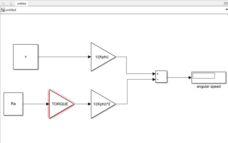
3. Develop a mathematical model of a DC Motor for the below equation using Simulink.
[ ω= V/Kϕ -Ra/Kϕ^2 .T]
ANS:-
mathematical model:-
Q4. Refer to the blog on below topic:
Induction Versus DC brushless motors by Wally Rippel, Tesla
Explain in brief about author’s perspective.
ANS :-
- According to the blog 'Induction vs DC Brushless motors by Wally Rippel, Tesla', the writer states the changes in the world years ago and the latest technological trends that are happening.
- He then explains about the DC Brushless motors and Induction motors.
- DC Brushless Machines:-
- According to him, the rotor has two or more permanent magnets that generate a DC magnetic field.
- This magnetic field will enter the stator core which interacts with the currents flowing in the windings to produce an interaction between rotor and stator.
- It needs a proper flow of current into the rotor and stator if it's not connected properly the current will not generate and the torque decreases.
- During the Electric and mechanical conversion when the rotor is rotating, the magnitude and polarity of the stator current will continuously vary such that the torque remains constant and optimal efficiency is achieved. Induction Motor:
- The 3-phase induction motor was invented by Nikola Tesla sometime before 1889.
- The stators for the 3-phase induction motor and the DC brushless motor are virtually identical.
- Both have three sets of distributed windings that are inserted within the stator core. The essential difference between the two machines is with the rotor.
- Unlike the DC brushless rotor, the induction rotor has no magnets.
- They have just stacked steel laminations with buried peripheral conductors that form a shorted structure.
- Currents flowing in the stator windings produce a rotating magnetic field that enters the rotor.
- The frequency of this magnetic field as seen by the rotor is equal to the difference between the applied electrical frequency and the rotational frequency of the rotor itself.
- An induced voltage exists across the shorted structure that is proportionate to this speed difference between the rotor and electrical frequency.
- The currents are produced within the rotor conductors that are approximately proportionate to the voltage, hence there's a speed difference.
- Finally, these currents interact with the original magnetic field to produce forces.
- When a 3-phase induction motor is connected to utility type 3-phase power, torque is produced at the outset.
- The motor has the ability to start under load. No inverter is needed. The fact that induction motors are directly compatible with conventional utility power is the main reason for their success.
- In contrast, a brushless DC motor produces no starting torque when directly connected to fixed frequency utility power.
- They really need the aid of an inverter whose phase is maintained in step with the angular position of the rotor.
- Differences:
- He then explained that there were only a few brushless drives in the past but now most of the Hybrid Electric Vehicles use it.
- There's a difference between brushless and inverter controls is the control. The Dc brushless requires a position sensor but an induction motor requires only a speed sensors.