Week-6 Challenge: EV Drivetrain
1. Which types of power converter circuits are employed in electric and hybrid electric vehicle?
Hybrid-Vehicle
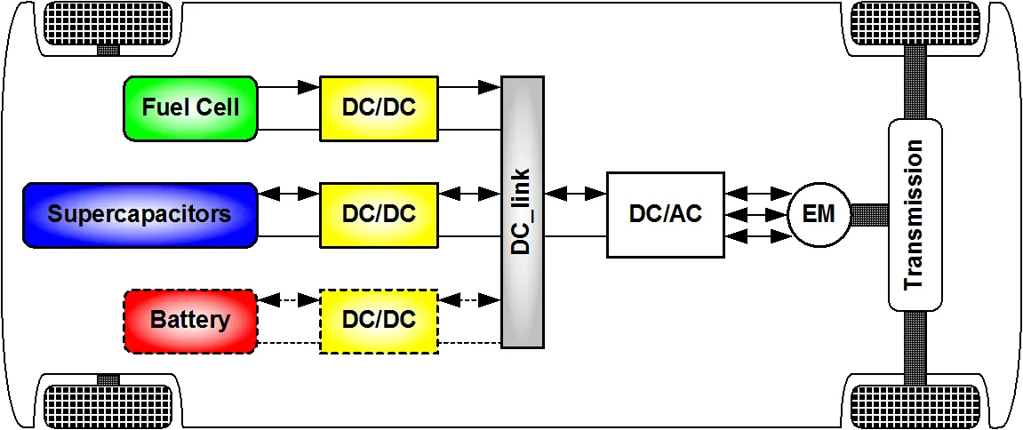
Electric Vehicle
The most common DC/DC - DC/AC converters can be grouped as follows:
1. Non-isolated converters
The non-isolated converters type is generally used where the voltage needs to be stepped up or down by a relatively small ratio (less than 4:1). And when there is no problem with the output and input having no dielectric isolation. There are five main types of converter in this non-isolated group, usually called the buck, boost, buck-boost, Cuk and charge-pump converters. The buck converter is used for voltage step-down, while the boost converter is used for voltage step-up. The buck-boost and Cuk converters can be used for either step-down or step-up. The charge-pump converter is used for either voltage step-up or voltage inversion, but only in relatively low power applications.
2. Isolated converters
Usually, in this type of converters a high frequency transformer is used. In the applications where the output needs to be completely isolated from the input, an isolated converter is necessary. There are many types of converters in this group such as Half-Bridge, Full-Bridge, Fly-back, Forward and Push-Pull DC/DC converters. All of these converters can be used as bi-directional converters and the ratio of stepping down or stepping up the voltage is high.
The selection of converters are completely based on cost and space constraints.
They were numerous topolgies that being used in electric vehicle based on enivronment requirement will change with emphasis on the soft-switching converters for DC motor drives, soft-switching inverters and multilevel inverters for AC motor drives. When a DC/DC converter is added to the electric propulsion system between battery and inverter, the voltage of the DC-bus can be maintained constant and the battery current can be maintained with relatively small ripples.
These converters include the pulse-width-modulated (PWM), resonant, quasi-resonant, multi-resonant, and non-linear resonant switch converters. Recently, soft-switched PWM converters have been gaining popularity.
The development of inverters for AC motor drives has become one of the key research areas in electric propulsion. The wish list of those inverters include efficiency over 95%, power density over 3.5 W/cm3, switching frequency over 10 kHz, dv/dt below 1000 V/µs, zero EMI, and redundancy with limp-home mode. To achieve this wish list, there are two major research directions, namely the soft-switching inverters and the multilevel inverters.
2. An Electric Vehicle's Drivetrain with 72V battery pack in shown in the diagram below. The duty ratio for acceleration operation is 'd1' and for the braking operation the duty ratio is2'. The other parameters of the electric vehicle is given below,
Motor and Controller Parameters:
Rated Armature voltage= 72 V
Rated armature current= 400 A
Ra= 0.5Ω, KΦ= 0.7 V-s
Chopper Switching frequency= 400 Hz
The vehicle characteristics are given by the equation
TTR=24.7+0.0051w2
What is EV steady state speed if duty cycle is 70%?
Ans:
the paramters given for separately exicted machine in the problem are
Rated armature voltage =72V // supply voltage // terminal voltage Vt
Rated Armature current = 400A // current consumed by rotor
Armature resisttance Ra =0.5 Ohm
constant flux KΦ= 0.7 V.s
speed-torque equation
ω=Vt/kϕ−Ra(kϕ)2τ
ω=50.4/0.7−0.5*T/(0.7)^2
ω=72−1.02T
T=70.58-0.98w
from vehicle characterstics equation T=24.7+0.0051w2
70.58-0.98w=24.7+0.0051w2
0.0051w2+0.98w-45.88=0;
at steady state the ev speed at 70% duty cycle wil be 371.75 rpm or -2206.71 rpm
Induction Versus DC brushless motors by Wally Rippel, Tesla
about author’s perspective:
The fact is BLDC is taking over the motoring applications in this technology era..
the word inverter technology is appearing in market which is infact BLDC motor because BLDC uses DC energy and converts it into controllable three phase supply to the motor.
its the voltage is being transformed from DC to AC thats why it is called as inverter motor.
The three phase induction motor is powered by ac source and works on induction which is difficult to control torque and speed only, the only control possibility is V/F control.
But in bldc dc link is used to maintain the voltage level and through switches in inverter, we can control the speed and torque with the help of position sensors via duty cycle and frequency or backemf through microcontroller.
Compared to induction motors, bldc is having high efficiency and less heat as stator part only is energized.
User can control torque and speed individually with the help of pwm modulation. while in ac induction, it is very complex and difficult to control.
eventhough BLDC is costilier than 3 phase induction motor, but due to increase in demand and production, BLDC motor is now cheaper than Induction motor
In this way BLDC dominated the todays motoring application, the name says its an DC motor but in actually it is an ac motor controlled by DC invertronics whose rotor is made of permanent magnets.