Week-6 Challenge: EV Drivetrain
Aim:
Understanding the EV drivetrain concepts .
Objective :
- Explain the power converters employed in EV and HEV.
- Find out the EV steady state speed if duty cycle is 70% for the given parameters.
- Prepare the simulink model for the given equation :
`ω= V/(Kϕ) -(Ra*T)/(Kϕ^2)`
- Explain in brief the author’s perspective in the given article.
Solution :
- Explain the power converters employed in EV and HEV.
Power converter circuits: Power electronic technology deals with processing and controlling the flow of electrical energy in order to supply voltages and currents in a form that optimally suited for end user’s requirements. The circuits which are used for converting are known as Power converter circuits.
The power electronic circuit consists of both power part and control part. Power part transfers the energy from source to load and it consists of power electronic switches (SCR or TRIAC), transformers, electric choke, capacitors, fuses and sometimes resistors.
The architecture of an EV drivetrain includes ESSs, converters, controllers, modulations, optimization and an electric motor.ESSs, including a battery, supercapacitors(SCs), a fuel cell(FCs) are connected to a DC-DC converter through a suitable controller and modulation schemes. The connection from the DC-DC converter to the electric motor is established through a high voltage (HV) DC bus follows by a DC-AC converter as shown in the figure below.
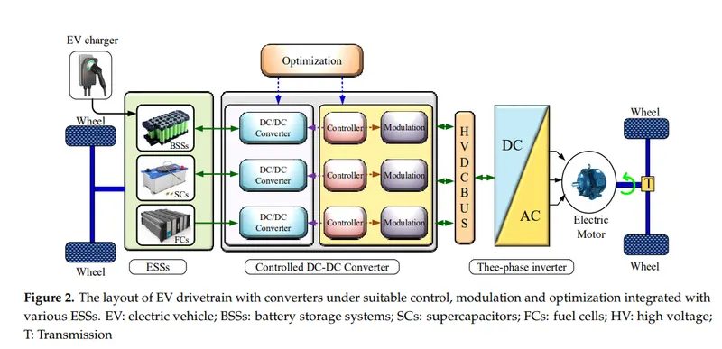
ESSs are responsible for delivering stable and consistent power to the motor; however, they suffer from unregulated behavior, voltage drops, and slow dynamic responses.
The battery storage system (BSS) exhibits compact size, high energy density and mature reliability and hence is suitable to provide a lifelong energy supply. The SCs offer low energy density but they have fast charging and discharging capabilities which make them ideal for delivering power instantaneously at high acceleration. Thus, the hybrid energy storage system combining BSSs and SCs can bring benefits in terms of long lifecycle, fast response, and low stress to the batteries; however, the cost of the entire storage system increases. In the case of FCs, they provide high energy density but have shortcomings including high cost, slow dynamic response, and limited supporting infrastructure.
The aim of the optimization in a converter is to achieve a low ripple current and reduce
converter loss, the number of components and development time
Depending on the type of function performed, power electronic converters are categorized into following types.
- AC to DC converter
- DC to AC converter
- DC to DC converter
- AC to AC converter
- AC to DC converter: This converter is also known as rectifier. It converts AC supply from the main lines to DC supply for theload. This converter contains various components like transformer, switching unit, filter and control block. The transfroms adjusts the primary AC source supply to the input of rectifier stage. The rectifier converts the low voltage AC supply into DC supply. Rectifiers are majorly classified into two types. They are:
Uncontrolled diode rectifiers
Controlled rectifiers
- DC to AC converters: This converter is also known as an inverter. These converters are connected between DC source of fixed input, and variable AC load. Most commonly, these DC to AC converters are called inverters. An inverter is a static device that converts fixed DC supply voltage to variable AC voltage. Here the fixed DC voltage is obtained from batteries or by DC link in most power electronic converters. The output of the inverter can be variable/ fixed AC voltage with variable/fixed frequency. These can be single phase or three phase inverters depending on the supply voltage. These converters are mainly divided into two groups.
One is PWM based inverters and other multilevel inverters.
Further, these are classified voltage source inverters and current source inverters. Each type is subdivided into different types such as PWM, SVPWM, etc.
Multilevel inverters are more popular in industrial applications.
- DC to DC converters: This converter is also known as chopper. Many DC operated applications need different levels of DC voltage from a fixed DC source. Some of these applications include subway cars, DC traction systems, control of large DC motors, battery-operated vehicles, trolleybuses, etc. They require variable DC to produce variable speed, so a power conversion device is needed. The output of the chopper can be less or greater than the input and also it can be fixed or variable. These can be unidirectional or bidirectional devices based on the application it is intended for. DC choppers are classified into three basic types based on input and output voltage levels. They are:
- Step-down or buck converter
- Step-up chopper or boost converter
- Buck or boost converter
- AC to AC converters: This converter is also known as cycloconverter or matrix converter. AC to AC converters connect an AC source to AC loads by controlling the amount of power supplied to the load. This converter converts the AC voltage at one level to the other by varying its magnitude as well as the frequency of the supply voltage. These are used in different types of applications including uninterrupted power supplies, high power AC to AC transmission, adjustable speed drives, renewable energy conversion systems and aircraft converter systems. There are two types of converters. They are:
- AC to AC voltage converters
- AC to AC frequency converters
- Usage of these converters in EV and HEV: These converters are used for various applications in EV and HEV vehicles.
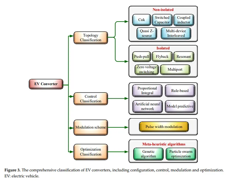
While the detail classification of the converters can be seen in following figure :
2. Find out the EV steadt state speed if duty cycle is 70%:
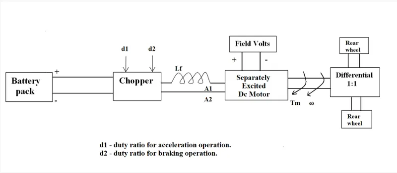
Given data :
Rated Armature voltage (Vbatt) = 72 V
Rated armature current (Ia) = 400 A
Armature resistance (Ra) = 0.5Ω
KΦ= 0.7 Volt second
Chopper Switching frequency= 400 Hz
Duty cycle (d) = 70% = 0.7
Torque speed characteristic is given as`T = 24.7 + (0.0051 * ω^2)` -- eqn1
Solution :
We know the motor characteristics given as :
`ω = (V/Kϕ) - ((T*R)/(Kϕ)^2)`
Substituting the values in the equation 2.
ω = ((72 * 0.7)/0.7) - ((T * 0.5)/(0.7)^2)
ω = 72 - (0.5T/0.49)
72 - ω = 0.5T/0.49
0.49(72 - ω) = 0.5T
35.28 - 0.49ω = 0.5T
T = 70.56 - 0.98ω ----eqn 2
Substitute equation 1 in equation 3
24.7 + (0.0051 * ω^2) = 70.56 - 0.98ω
0.0051 * ω^2 + 0.98ω = 70.56 - 24.7
0.0051 * ω^2 + 0.98ω - 45.86 = 0
It is polynomial equation with second degree. By solving we get the postive value as
ω = 38.915
Therefore, the steady state speed of EV if duty cycle 70% is 38.915 rad/s
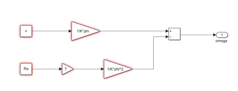
3. Prepare the simulink model for the equation
`ω= V/(Kϕ) -(Ra*T)/(Kϕ^2)`
4. Authors perspective in brief for the article https://www.tesla.com/blog/induction-versus-dc-brushless-motors:
- At the starting of the article, the author explains the fact that none is best in the world of this automobile. He states the example of the ICE engine types as flathead, inline, V configuration, and many other. Each engine configuration holds its importance based on its purpose and condition. Same like he explains the battery technologies that started with the lead-acid battery and now its lithium.
- Getting the main content of the article, he starts explaining the construction of the DC brushless and induction motors.
- He starts with a DC brushless motor. When the motor runs, it is necessary that the magnitude and polarity of the stator currents be continuously varied and the torque should be constant and electrical to mechanical conversion is optimally efficient. This can be done by the inverter and motors are useful without these.
- Induction rotor doesn't have magnets,they have stator windings that produce the magnetic field and the rotor contains stacked steel laminations with buried peripheral conductors which forms a small structure.
- Both motors contain the same type of stators which contains three sets of distributed windings.The main difference between these two is rotor.
- When induction motors are used, there is no need of inverters. Induction motors are directly compatible with conventional utility power, where, inverters are needed for DC brushless motors to develop torque. The phase is maintained in step with the angular position of the rotor.
- He then tells a point wherein the if the induction motor is coupled with the smart inverter, the motor is then good to with EV vehicles with all the advantages of the DC motors like running on battery and variable speed.While the disadvantage of the DC motors is that they cannot be connected with the utility power and they need inverter everytime.
- Further he makes some comparison between the two motors emphasising more importance to the induction motor like losses are less (unlike the eddys, hysteresis and I^2R losses in DC motors )if run with a smart inverter, cost of the machine is less as compared to the other. One important point he denotes is that in induction motor as the machine size grows the overall losses won't grow and it will be a favorable choice to go with an induction motor where high performance is needed.
- Now, he discuss the major drawback of the induction motor like heating issues and unity power factor. The unity power factor is 85% in case of induction motor while the DC machine is able to operate at unity power factor. Other things he mentioned is that peak torque possibilities is less in induction motor.
- Lastly, the author wants to conclude his idea though the induction motor with some extra attachments has some advantages over DC machines still cannot cope up with the future applications in EV due the difficulty in controlling the induction motors. He then specifically mentions that DC brushless drives will likely continue to dominate in the hybrid and coming plug-in hybrid markets, and that induction drives will likely maintain dominance for the high-performance pure electrics.
Power factor :
In simplest terms, VI product defines power in DC, where only component that matters is resistance. In AC, there is capacitance and inductance, apart from resistance. So the product VI no more represents real active power, but is termed as apparent power. It is only resistive component of this power, which represents active power, or work done.
The ratio of active power to apparent power is called as power factor. When power factor is unity, or 1, it means the entire apparent power is being used for active work being done, or active power.
This is the ideal condition desirable, but not attained in practice most of the time. In power systems from utility, this generally varies between 0.9 to o.98, depending on load.