Week-6 Challenge: EV Drivetrain
Which types of power converter circuits are employed in electric and hybrid electric vehicle?
Description : Power Converters ---> The task of a power converter is to process and control the flow of electric energy by supplying
voltages and currents in a form that is optimally suited for the user loads.
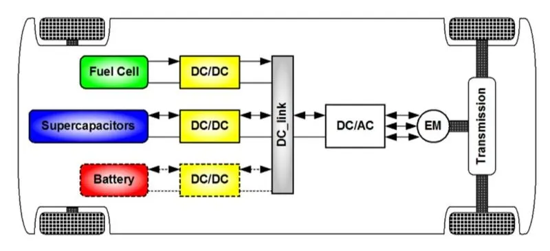
The power semiconductor devices or power electronic converter fall generally into six categories :
-AC to DC Converter (Controlled Rectifier)
-DC to DC Converter (DC Chopper)
-AC to AC Converter (AC voltage regulator)
-DC to AC Converter (Inverter)
-Static Switches
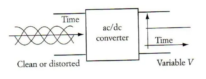
AC to DC Converter (Controlled Rectifier): An AC to DC converter circuit can convert AC voltage into a DC voltage. The DC output voltage can be controlled by varying the firing angle of the thyristors. The AC input voltage could be a single phase or three phase.
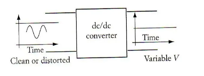
DC to DC Converter (DC Chopper) : These converters can converter a fixed DC input voltage into variable DC voltage or vice versa. The DC output voltage is controlled by varying of duty cycle.
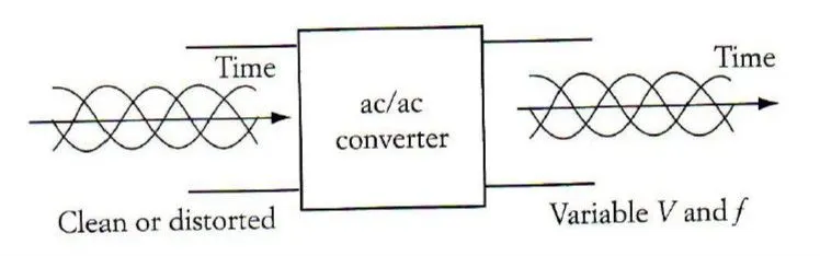
AC to AC Converter (AC voltage regulator): This converters can convert from a fixed ac input voltage into variable AC output voltage. The output voltage is controlled by varying firing angle of TRIAC. These type converters are known as AC voltage regulator.
DC to AC Converter (Inverter) : DC to AC converters are called as inverters. An inverter is a static device that converts fixed DC supply voltage to variable AC voltage.
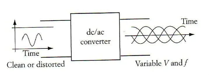
Here the fixed DC voltage is obtained from batteries or by DC link in most power electronic converter. The output of the inverter can be variable/ fixed AC voltage with variable/fixed frequency.
This conversion from DC to AC along with variable supply is produced by varying the triggering angle to the thyristors.
Objective 2:
An Electric Vehicle's powertrain with 72V battery pack in shown in the diagram below. The duty ratio for acceleration operation is 'd1' and for the braking operation the duty ratio is 'd2'.
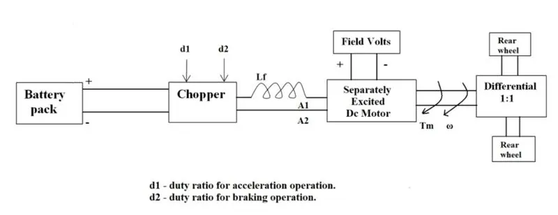
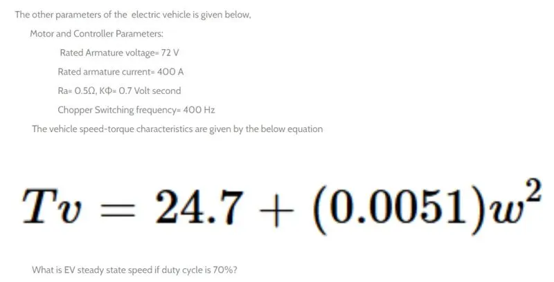
Solution: The steady state speed is that speed where the characterstic speed torque equation for vehicle is intersecting the characterstic motor torque and speed equation.
The characterstic torque speed equation for vehicle is
`T=24.7+(0.0051)omega^2`
The characterstic speed and motor torque is
`omega = v/(k*phi)-R_a/(k*phi)^2*T`
where, T is the toruqe produced by motor
V = rated armature voltage
R_a = armature resistance
K*phi = motor constant
Rearranging the above equation
`(v/(k*phi)-omega)*(k*phi)^2/R_a = omega
Now by equating both the equation we can obtain 'Steady angular speed'
`(v/(k*phi)-omega)*(k*phi)^2/R_a = 24.7 +(0.0051)omega^2`
V_actual = V* duty ratio
V = 72 * 70/100 = 72*0.7
`((72*0.7)/(0.7)-omega)*(0.7)^2/0.5 = 24.7 +(0.0051)omega^2`
We get a quadratic equation
`0.0051*omega^2+0.98*omega -45.86 = 0`
Solving the above equation we get
`omega`= 38.915 rad/s and -231.072 rad/s
We can simply ignore the negative root i.e -231.072 rad/s
Therefore, the steady state speed for 70% duty cycle is 38.915 rad/s.
Objective 3: Refer to the blog on below topic:
Induction Versus DC brushless motors by Wally Rippel, Tesla
Explain in brief about author’s perspective.
Explaination:
In this blog the author discuss about pros and cons of DC brushless and Induction motor (w.r.t electric vehicles)
Now a days both DC brushless motor and Induction motors are widely being used.
DC brushless motor consists of sets of permanent magnets while in Induction motors permanent magnets are absent.
In BLDC motor the magnetic field due to permanent magnets interacts with the current flowing in the windings to produce torque between rotor and stator.
In induction motor instead of magnets there are just stacked steel laminations with buried peripheral conductors that form a “shorted structure. Current flowing in the stator winding produces the rotating magnetic field
BLDC motor requires a inverter to be started it cannot be directly connected to the main power. While Induction motor can be directly connected to main source.
Rotor heat is less in DC brushless drive compared to Induction motor.
DC brushless drives require an absolute position sensor, while induction drives require only a speed sensor; these differences are relatively small.
In BLDC "B" magnetic fiels is not adjustable due to which there is more eddy losses while in induction motor magnetic field is adjustable.
Induction machines are more difficult to control. The control laws are more complex and difficult to understand. Achieving stability over the entire torque-speed range and over temperature is more difficult with induction than with DC brushless.
Conclusion: Both DC brushless motor and Induction motor will continue to dominate the hybrid EV industry. And both will be used for upcoming era according to suitable requirements.