Meshing of hood
OBJECTIVE: To mesh the hood of the vehicle along with its component like latch reinforcements, hinge reinforcements and the inner body according to the following quality criteria.
Target element length = 5mm
|
S.N |
Quality Criteria |
Value |
|
1 |
Aspect Ratio |
5 |
|
2 |
Skewness |
45 |
|
3 |
Warping |
15 |
|
4 |
Taper |
0.5 |
|
5 |
Min. Length |
2mm |
|
6 |
Max. Length |
8mm |
|
7 |
Min angle Quad |
45 |
|
8 |
Max angle Quad |
135 |
|
9 |
Min angle Tria |
20 |
|
10 |
Max angle Tria |
120 |
PROCEDURE: I have worked separately on each component and most of the steps are common for every component which are as follows:
STEP1 : Geometry is imported by going to Tool bar>Import Solver Deck>Import Geometry>File type>STEP>Location where the file is saved.
STEP2 : Since 2D meshing is to be performed therefore solids were deleted after importing the geometry.
STEP3 : Manual geometry cleanup is performed on the parent component and mid surface is extracted by going to Menu pages > Geometry> mid surface. Here in extraction option, ‘Offset’ is selected since here we are dealing with the components having lots of fillets.
These extracted mid surface are collected in separate collectors and appropriate properties including material, card image, thickness etc are assigned.
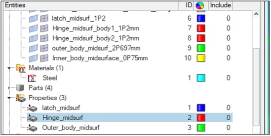
STEP4 : Again manual geometry cleanup is performed on the extracted mid surface.
STEP5 : Before meshing quality criteria parameters are entered by going to menu bar > preferences > criteria file settings.
STEP6 : Meshing is done by taking target element size as 5mm and element type as ‘mixed’. Some general rules should be followed while doing meshing which are as follows:
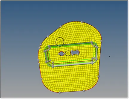
- Back to back triangles should be avoided. Two tria element should not connect to each other directly. Below figure represents back to back triangle element present in the hinge component. This can be resolved by dragging triangle eleme/nt to some different place or remeshing the triangle elements along with few surrounding element.
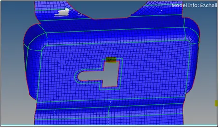
- Triangle elements should be avoided on outer edges and holes. Tria elements should also not touch the feature lines. Below figures represents the tria element touching the feature line of the latch component. This should be avoided.
- Holes should be modeled carefully with even number of equally spaced elements.
- Nodes should lie exactly on the edges. The below figures represents the magnified view of the latch component.
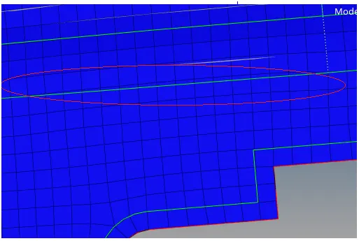
Here you can clearly see that the mesh have not properly captured the features lines. This can be resolved in two ways. In first method go to Menu pages > geometry > node edit > align node. Selects 1st and 2nd nodes as the reference node that means in the direction in which you want to align the rest of the node. After that select those node which are not capturing the feature line and click align.
In second method you can simply project the deviated nodes to the feature lines. This can be done by going to menu pages > tools > project > to line. Select the deviated nodes and after that select the feature line on which you want to project these nodes and click project.
- Instead of zig zag distribution, structured or smooth mesh is recommended. This can be done by going to menu pages > 2D > Smooth. Select the element which you want to smooth.
- For crash analysis tria element are preferred over rotational quad and for structural analysis rotational quad are preferred over tria.
- For the component having symmetry, we only have to work on one side and for the other side the surface and the mesh can be reflected. In this assignment, the outer body is symmetric with respect to y axis and also the inner body part except that latch portion is symmetric. Therefore geometry cleanup and meshing is performed only on one side and for the other side, surface and meshing is reflected.
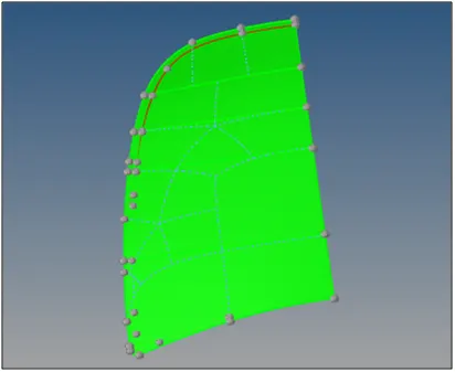
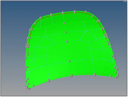
The above figures show the outer body part. As you can clearly see in the figure, the part is symmetric about y axis. Therefore geometry cleanup and meshing is done only for one part and for the other part, surface and mesh is reflected. Reflection is done by going to menu pages > tool > reflect > element. Element which are to be reflected are then selected, Base node about which the reflection is to be done is defined and finally the reflection is done by clicking on reflect button.
The below figure represents the half side of the inner body. Since the part is symmetric therefore geometry cleanup and meshing is performed only on one side.
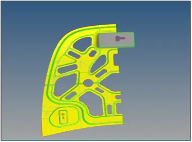
Then this surface and mesh is reflected and the latch portion is meshed separately.
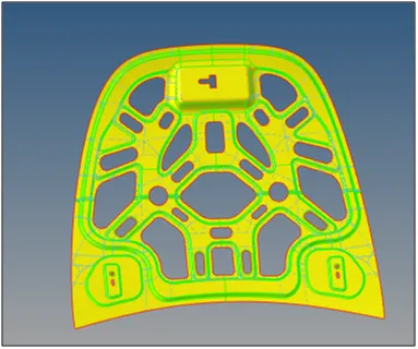
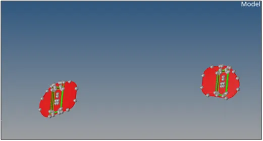
Since we have two hinge parts therefore I have worked only on one hinge part and mesh is reflected for the other part by defining a base node between the two hinge surfaces.
STEP7 : After meshing elements are checked for quality criteria and this is done by going to menu pages > 2D > quality index or by simply pressing f12 key. Elements which fail to satisfy quality criteria are then identified and resolved by using element clean up tools. Most of them got resolved by element optimization and place node option. Tria elements can be dragged out by using drag tria option. At some places where these options fails to remove warpage, then it is removed by going to menu pages > tools > translate. Select one node of the warpage element and rest of the nodes of the element are select as planar nodes. Magnitude of translation is to be given as 0.1 and thus by using translation such kind of warpage is removed.
STEP8 : Elements in the hemming area in outer body part are failing for minimum element length. It’s ok since hemming is the important feature and we cannot disfeature it.
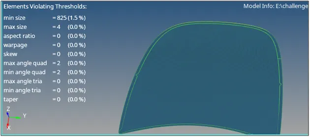
STEP9 : After element quality check, parts are checked for free edges which is done by going to menu pages > tools > edges. All the elements are selected and then checked for equivalence by clicking on preview equivalence. Nodes which are not connected properly are then identified by it and then they all are connected by clicking on equivalence option. Still some disconnected nodes are left which are then identified by clicking on free edge option. Then connections are made manually by going to menu pages > 2D > replace.
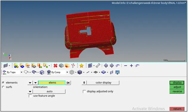
STEP10 : After this elements are checked for the normal direction. The direction of normal should be same for each and every element and for every components. This can be checked by going to menu pages > tools > normals. Below figure represents the latch component, as you can see that every element are colored in red that means the normal for every element is in same direction
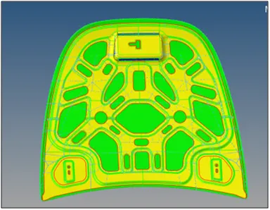
RESULT: Final image of the model is attached below :-
LINK: The link of the model is attached below
https://drive.google.com/file/d/17dsIxoYq3ksO4z0BnPZk_b7EU46-j9Bn/view?usp=sharing