Week 6- Challenge
PREPROCESSING OF HOOD MODEL OF A CAR USING HYPER MESH
Aim
Prepare the given hood model for post-processing analysis, steps involved are,
- Perform geometry cleanup
- Extract mid-surface
- Mesh the component with given element quality criteria
Procedure
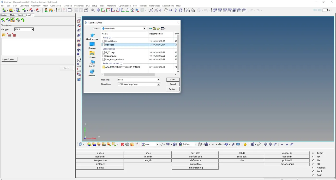
1) First import the geometry using import geometry option and select the IGES file,
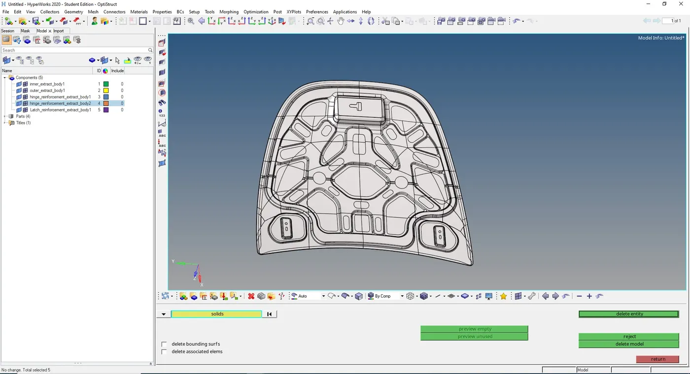
2) Hood model is imported as shown in figure below,
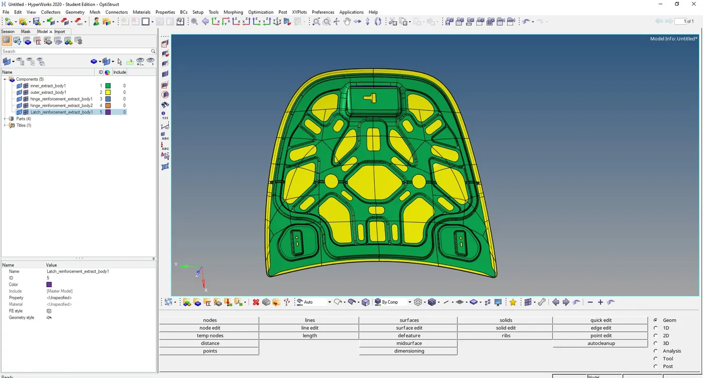
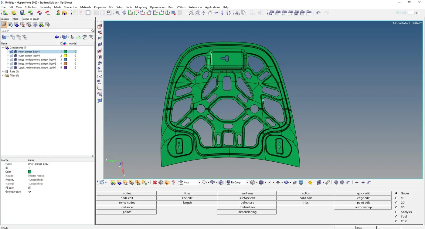
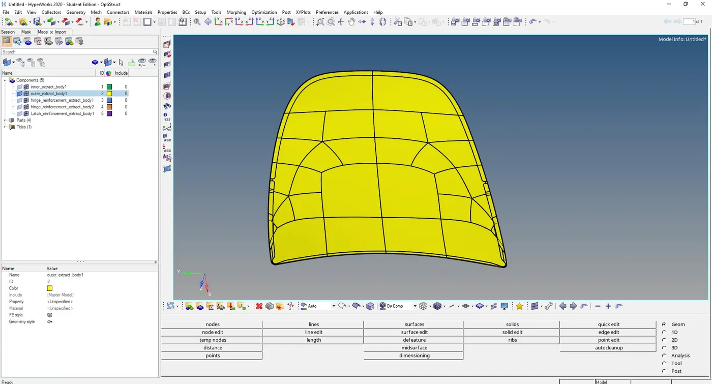
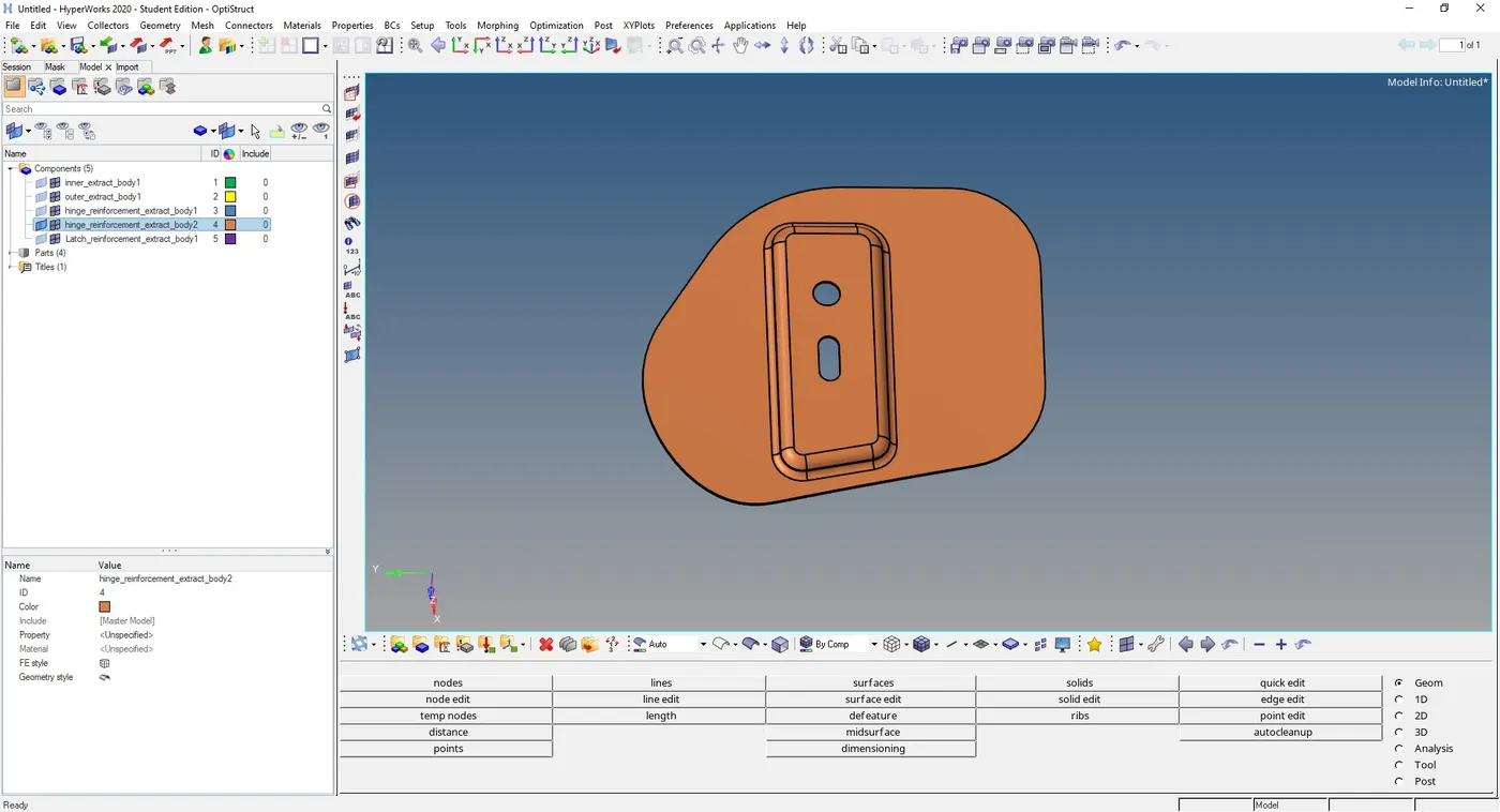
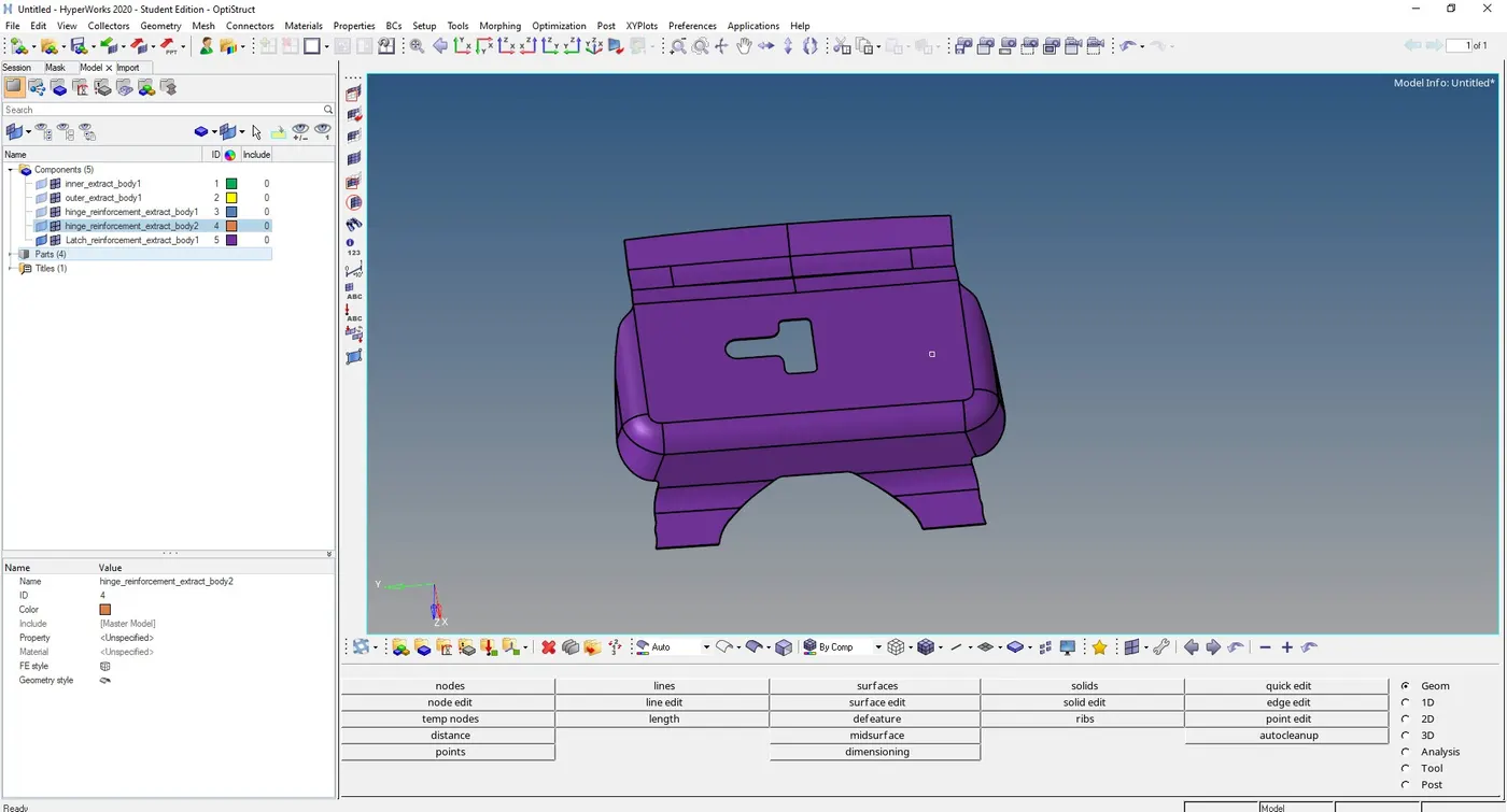
Components involved in the hood model are,
Inner extract outer extract
Hinge reinforcement Latch reinforcement
3) First we need to delete the solid body, go to Delete -> select solids ->left click on the selection and choose all -> delete entity
3) Geometry Cleanup
First step for any Geometrical error checkup is to perform a visual inspection of the model, In order to check the geometrical errors ,
switch Geometry visualization type to By Topo
all free edges are displayed in red colour and shared edges in green, T- junction edges in yellow and suppressed edges in blue.
switch on Display fixed points inorder to see the ponts on the surfaces.
In the next step we need to check for free edges and start filling missing surfaces
There are several options to fix the missing surfaces first option is to,
a) Geometry -> Quick edit -> Filler surfaces, and select the free edge
(b) go to Geometry -> Surfaces -> Ruled surfaces, select the first and second line lists and click create.
c ) Geometry -> Edge edit -> Replace, select the edge to be moved and edge to be retained also set the cleanup tolerance value and click replace.
4) Extraction of Mid-surfaces
In order to extract mid-surfaces go to, Geometry -> Mid-surface -> select the extraction option as "skin offset"
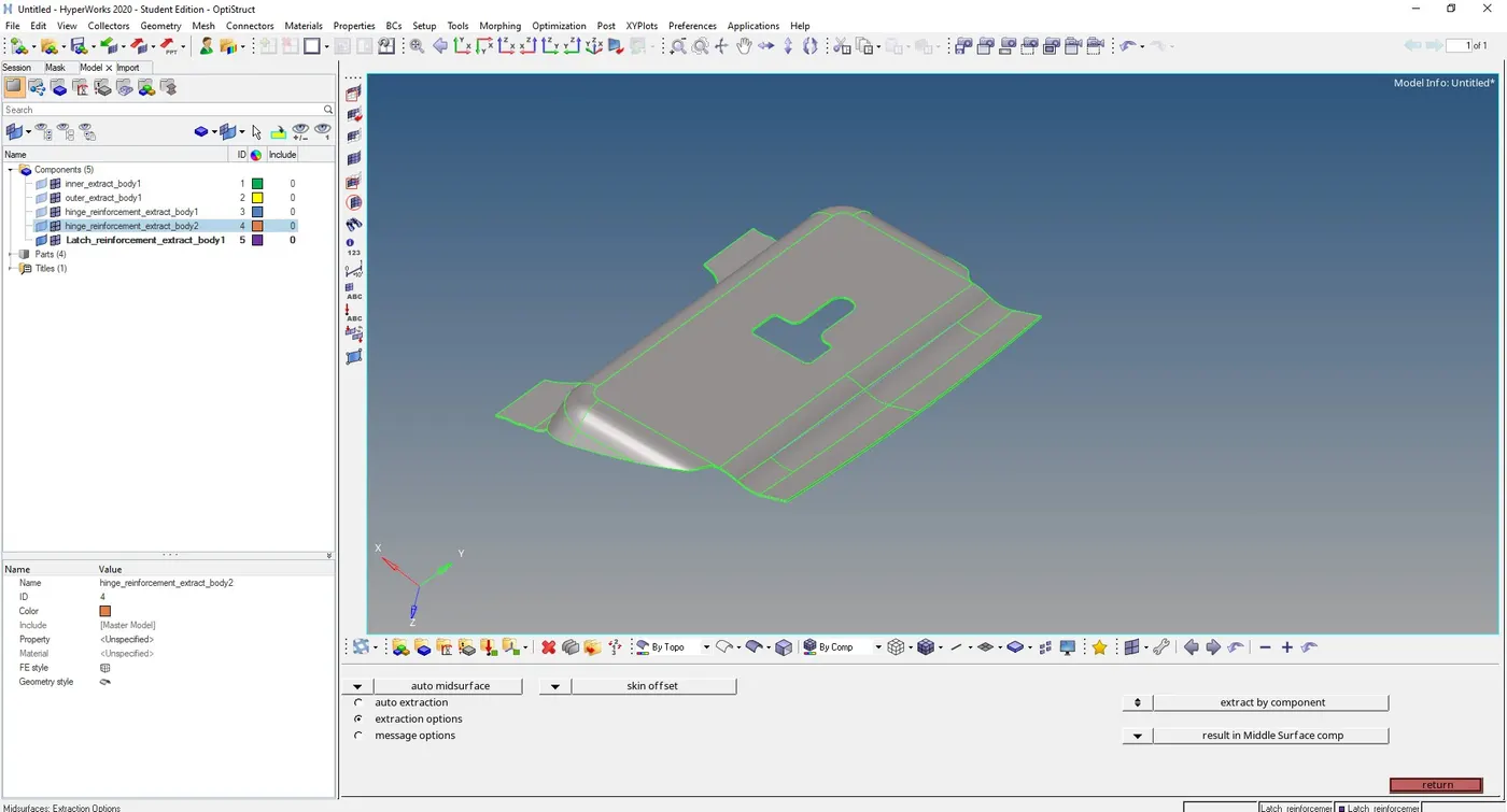
then go to Auto mid-surface extraction and click on extract to generate mid-surface
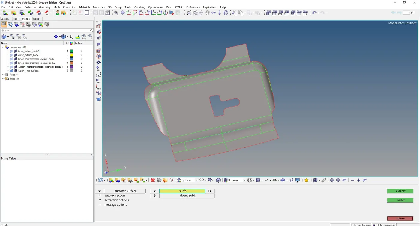
now we can defeature the edges which will fail for minimum element length using, Geometry -> Quick edit -> toggle edge -> select the edges to suppress.
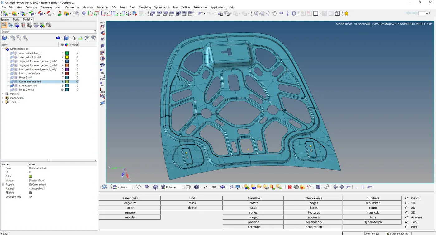
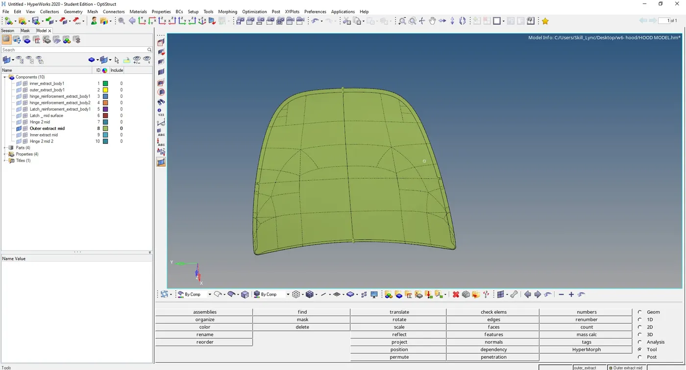
similarly we created mid-surface for all components separately, figure below shows extracted mid-surfaces of all components
Latch reinforcement mid-surface
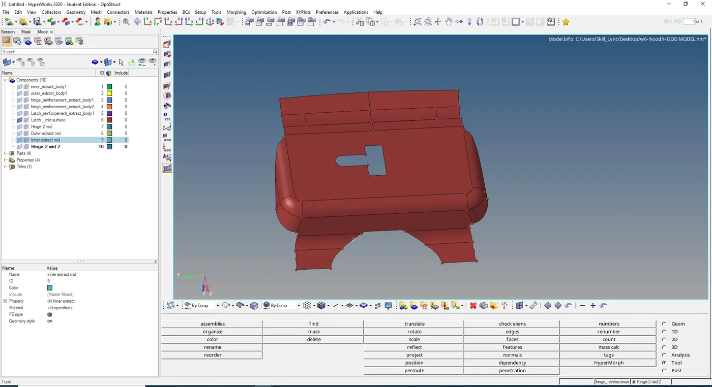
Hinge reinforcement midsurface
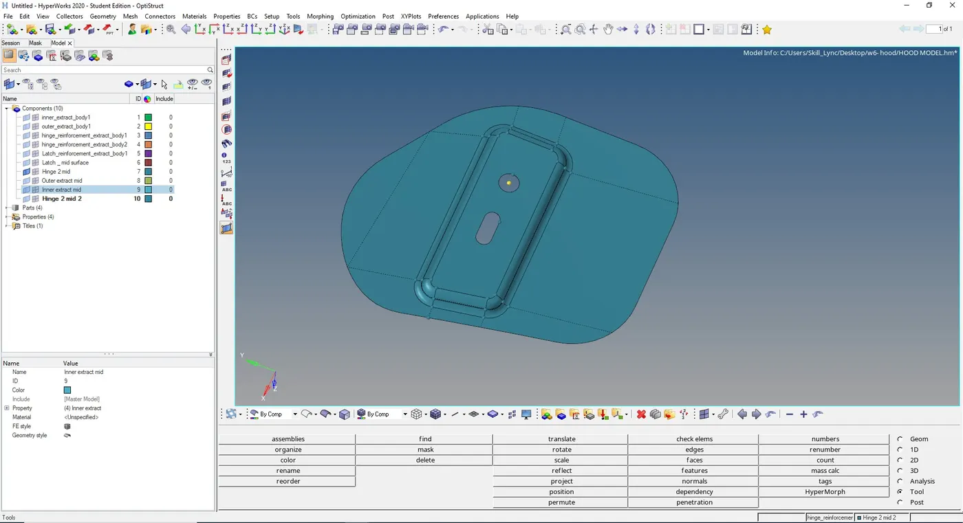
Inner extract mid-surface
Outer extract mid-surface
5) Meshing the component with given element quality criteria
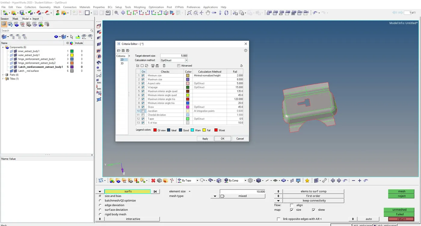
a) First we need to enter the element quality criteria, go to Preferences -> Criteria file settings and enter the values.
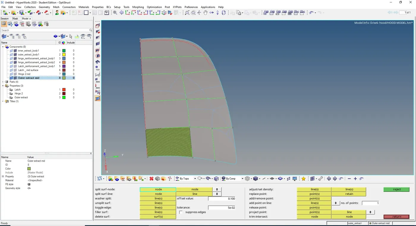
b) now we need to creates cuts on the surface and mesh them one by one in order to get a good mesh flow and to get a checks on trias
to creates cuts, go to Geometry -> quick edit -> split surface nodes/ split surface lines
c ) To create a mesh, go to 2D -> automesh -> select the surface and choose the element size and type of elements -> mesh
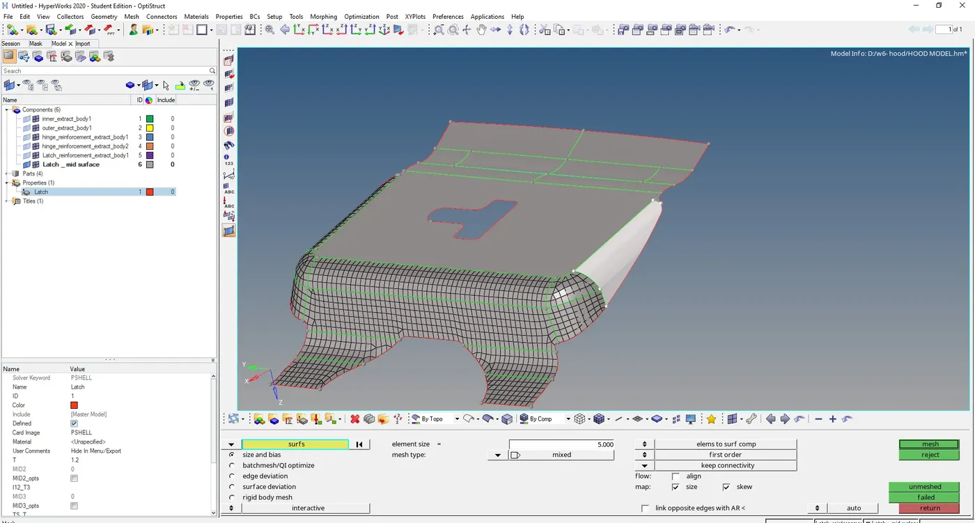
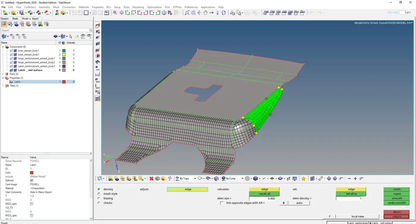
we can change the elemennt density by increasing or decreasing the number of nodes, left mouse click to increse and right mouse click to decrese.
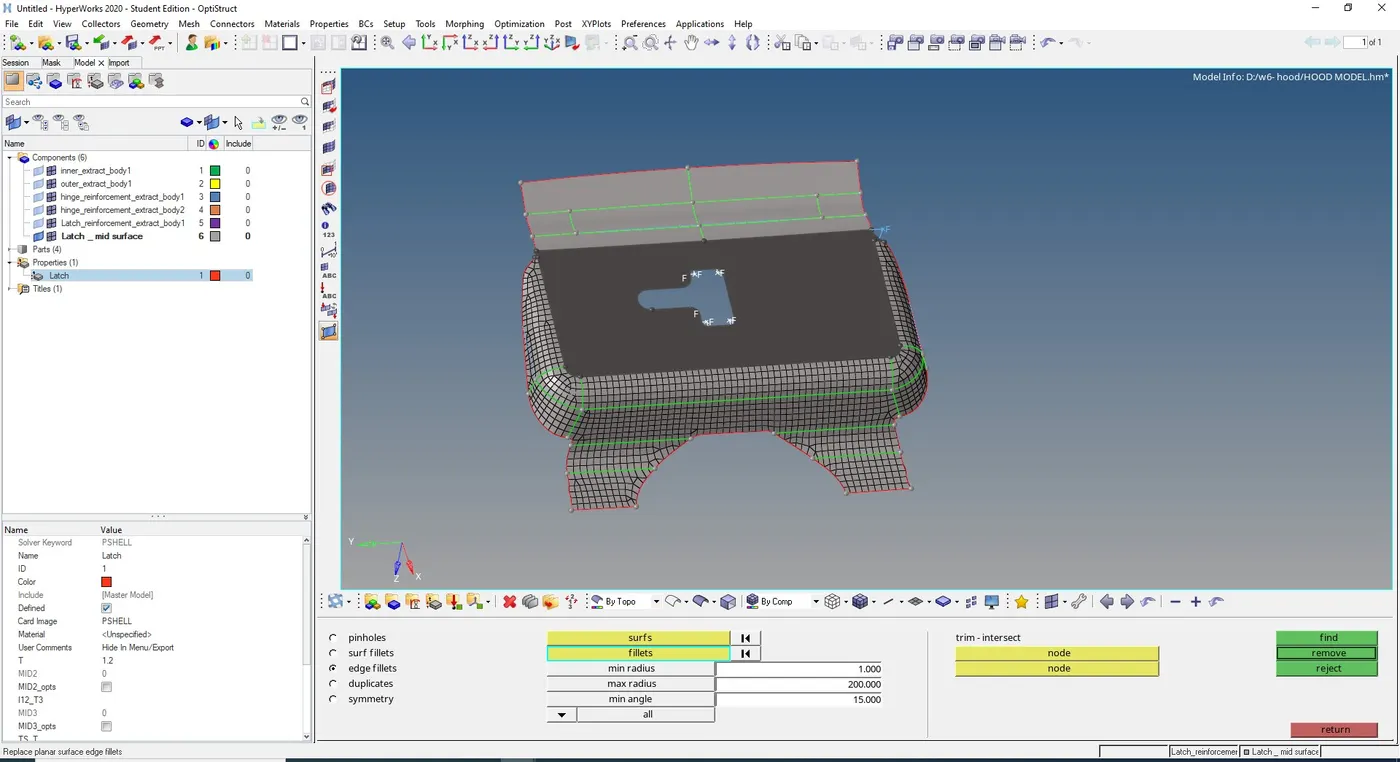
d) we can defeature the edge fillets in latch area using geometry -> defeature - > edge fillets -> input the diameter -> find -> edge fillets will be highlighted and we can remove
e ) similarly mesh all the surfaces of every component and in order to check for quality go to, 2D -> quality index. and failed elements will be highlighted.
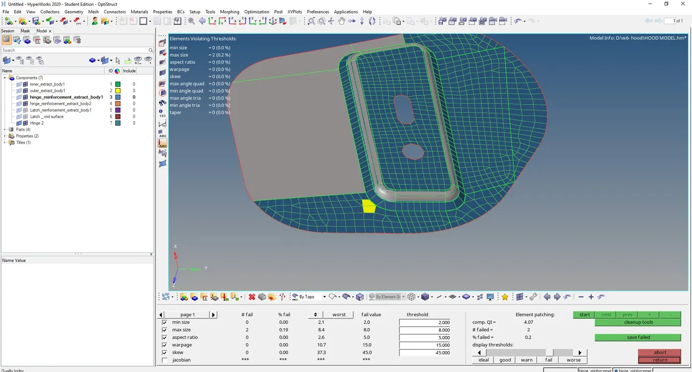
In order to clear the quality of failed elements got to 2D -> quality index -> cleanup tools,
you can use drag tria element tool to drag and combine opposite tria element ,also we can use swap edge tool to swap tria from free edges
also use smooth option to clear the quality
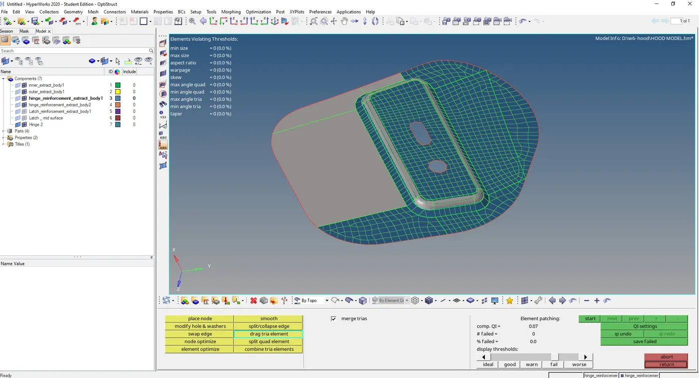
similarly we can create mesh on every mid-surface extracted.
Meshed Inner extract component
Inner panel is symmetric , so we only mesh half portion of inner extract panel
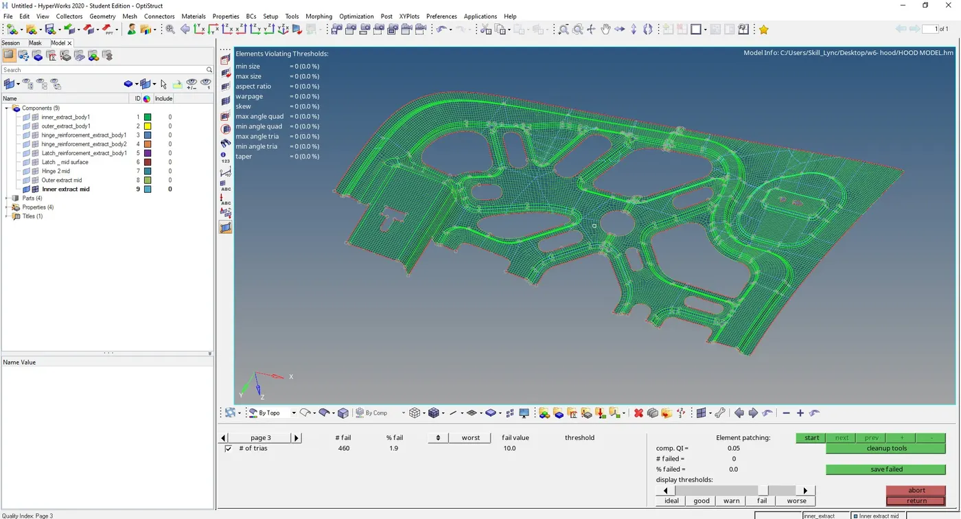
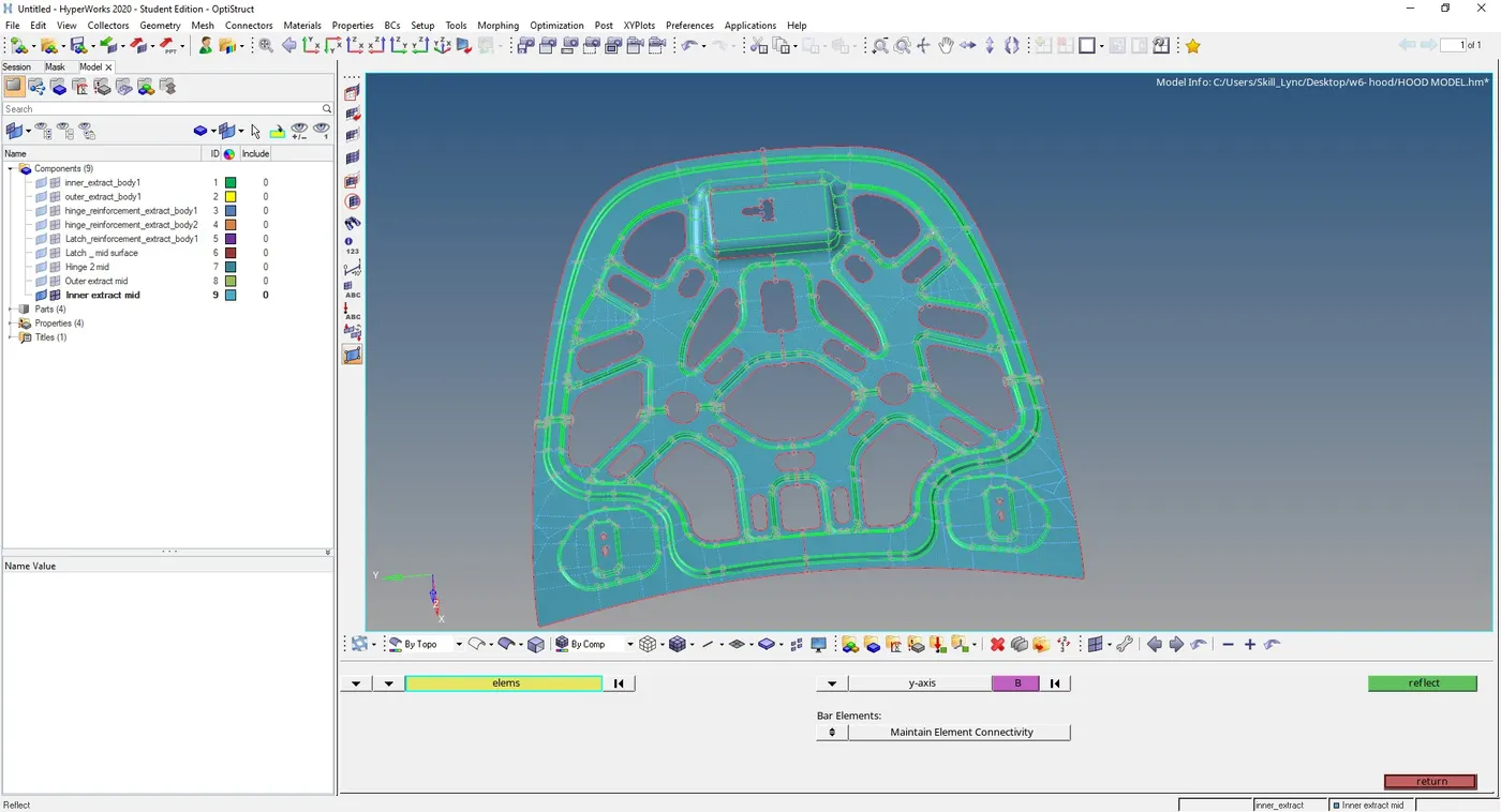
we can reflect the half portion to otherside using, Tool -> Reflect -> select the axis to reflect -> select all elements and duplicate it -> select a Base point and reflect
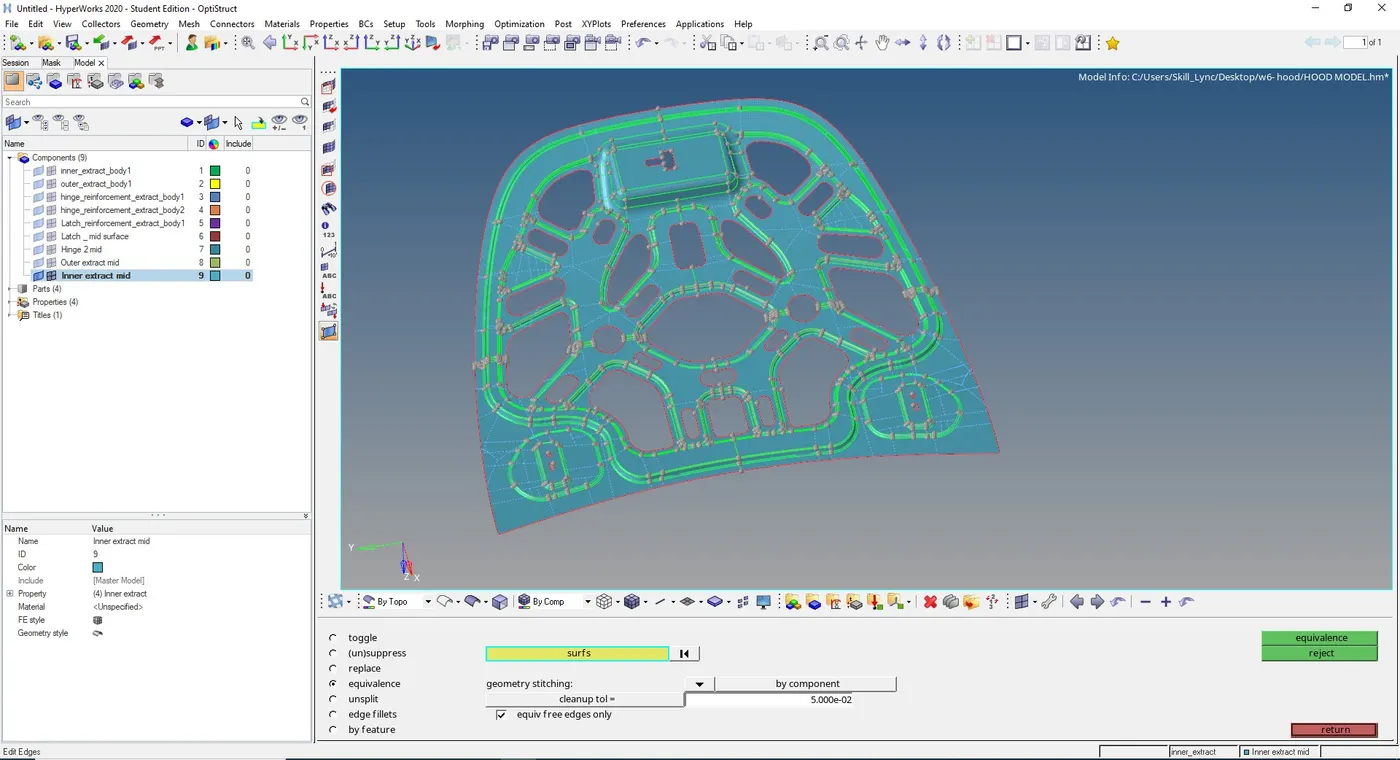
Inorder to give connectivity between reflected parts, go to Tools -> edges -> select the component -> give tolerance value -> select preview equivalence - > equivalence
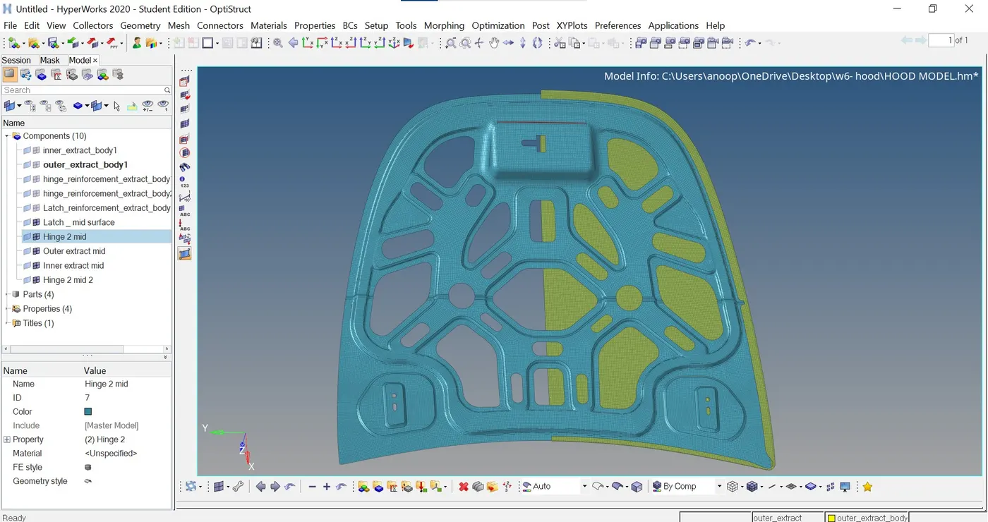
Final meshed mid-surface of Inner extract
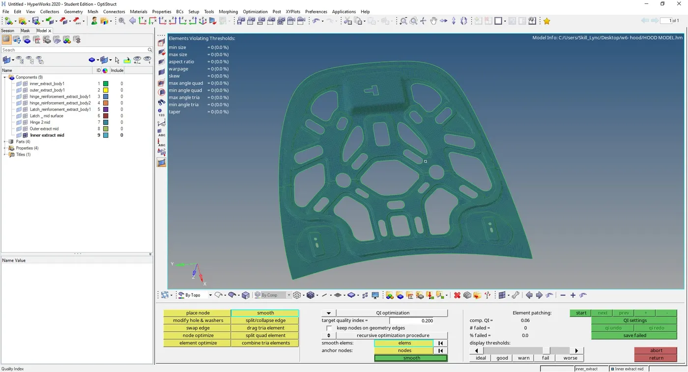
Meshed outer extract component
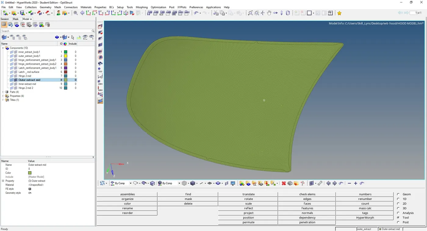
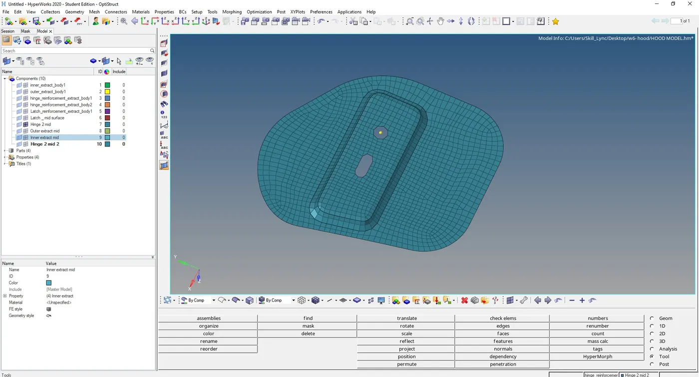
Meshed Hinge reinforcement
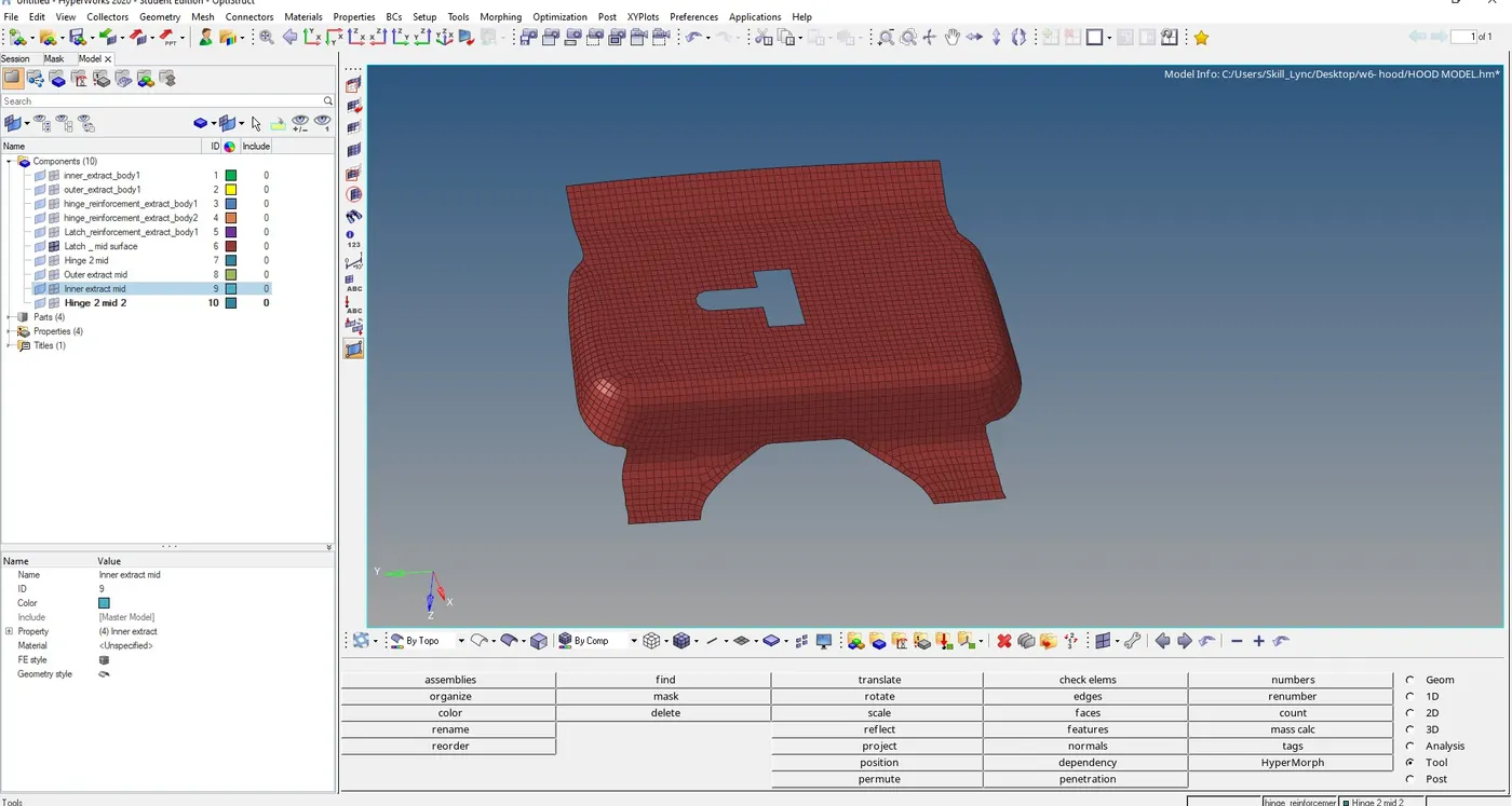
Meshed Latch reinforcement
Giving Thickness to the shell elements
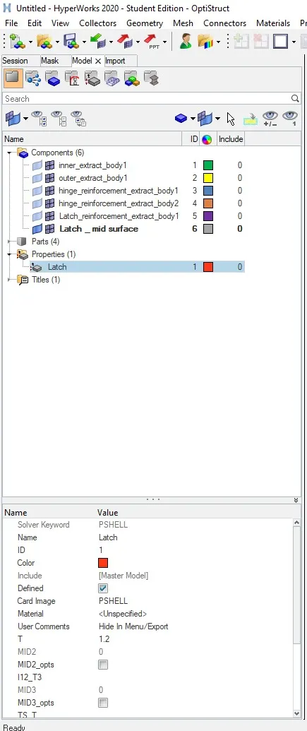
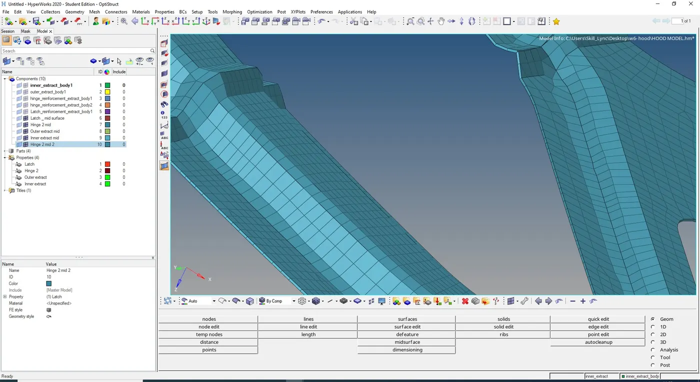
In order to give thickness to the shell elemts we need to create a property and give thickness of the component to the propert and assign the property to the mid-surface component and change visibility to 2D detailed element representation.
Result
Performed geometry cleanup and extracted mid-surface of Hood model of car and meshed the component with given element quality criteria and assigned thickness to the shell elements
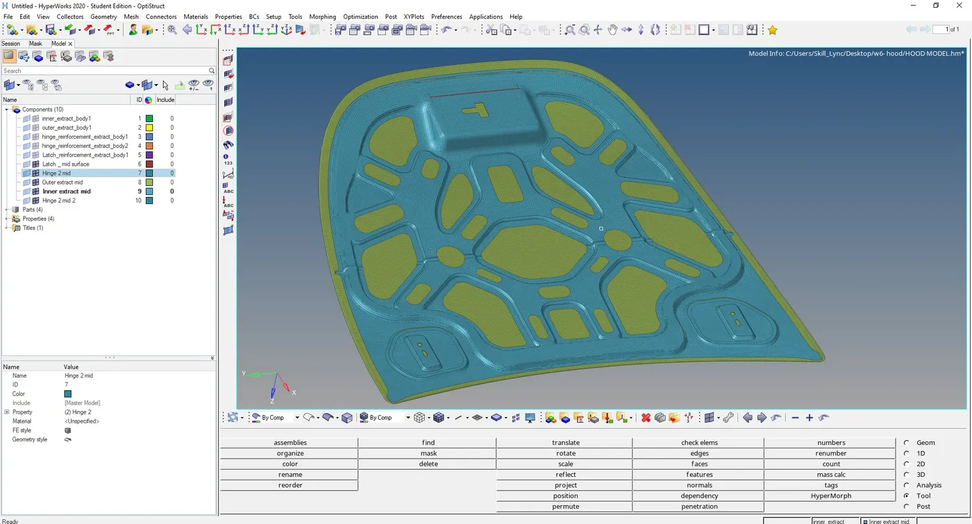
Because HyperMesh student version dosen't support more than 100000 elements i dosen't reflect half portion of outer extract, in order to keep total numner of elements below 100000.