Meshing the Hood Model Using HyperMesh
Aim:
The main aim is to generate a mid- surface and to create a mesh for the given Hood model.
Methodology:
The Methodology is for the hood model is as follows.
- Opening the File.
- Creating the Mid surfaces.
- Giving Quality Criteria.
- Generating the mesh.
Theory:
Hood:
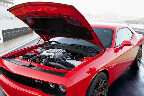
The hood or bonnet is the hinged cover over the engine of motor vehicles. Hoods can open to allow access to the engine compartment or trunk on rear-engine and some mid-engine vehicles) for maintenance and repair.
On front-engine cars, the hood may be hinged at either the front or the rear edge, or in earlier models (e.g. the Ford Model T) it may be split into two sections, one each side, each hinged along the centerline. A further variant combines the bonnet and wheel arches into one section and allows the entire front bodywork to tilt forwards around a pivot near the front of the vehicle.
Hoods are typically made out of the same material as the rest of the bodywork. This may include steel, aluminum, fiberglass, or carbon fiber. However, some aftermarket companies produce replacements for steel hoods in fiberglass or carbon fiber to make the vehicle lighter.
Procedure:
- Opening the File:
- The file is in the .stp
- The file is initially imported from the Geometry.
- Select STEP in from File Type.
- Select the File and Click Import.
- The file is opened. Click the ‘f’ key to fit the image into the screen.
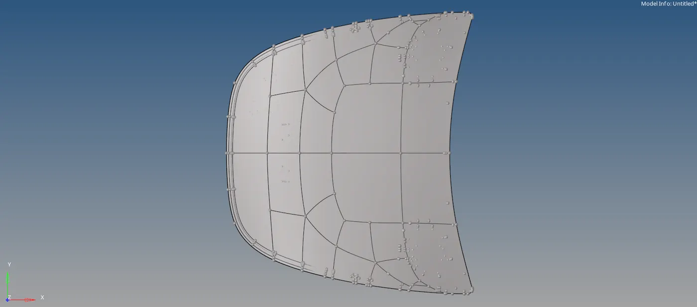
Front Part:
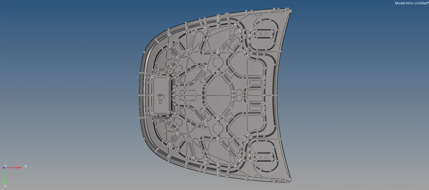
Overall Part:
- Creating the Mid Surface:
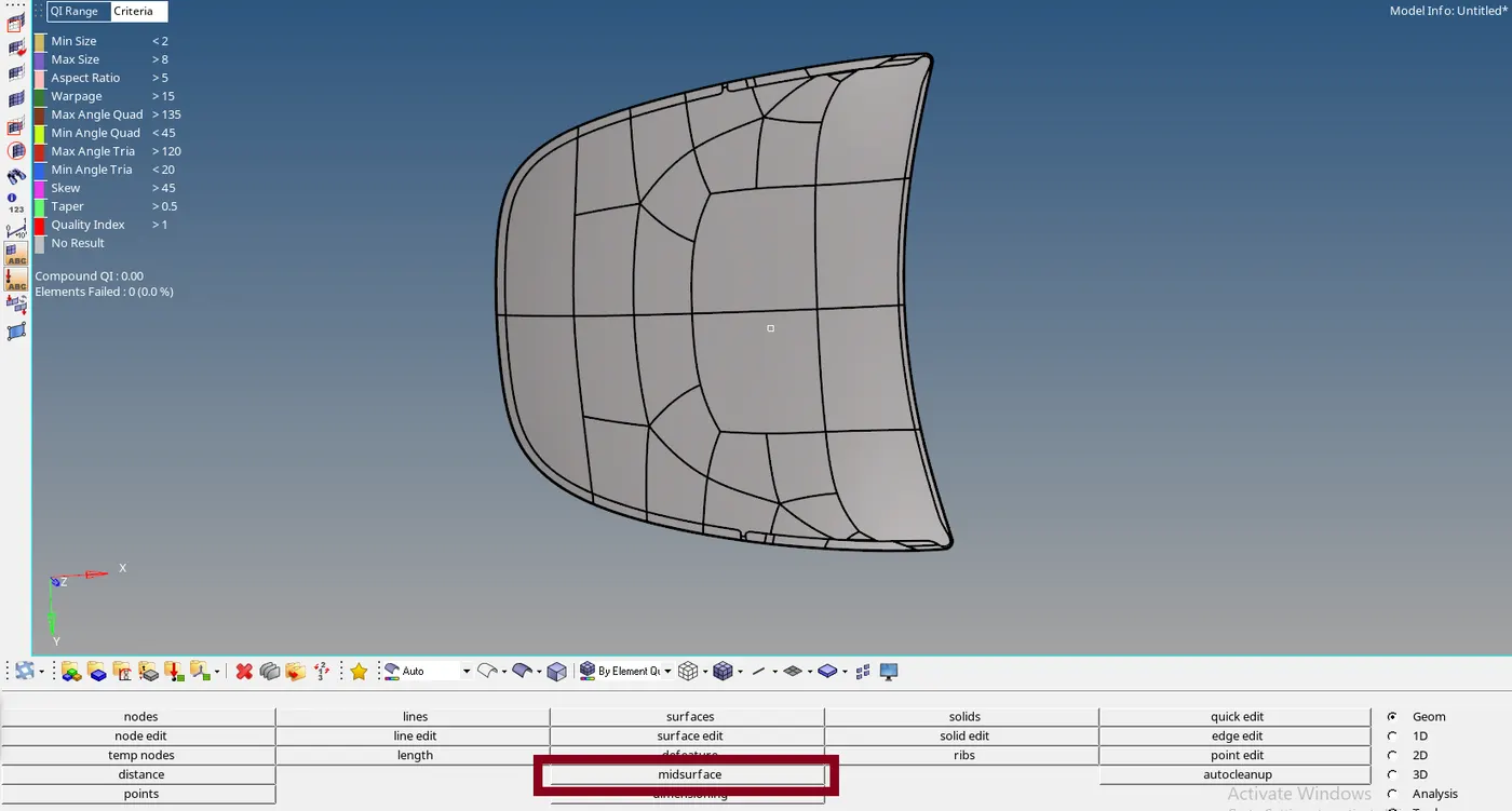
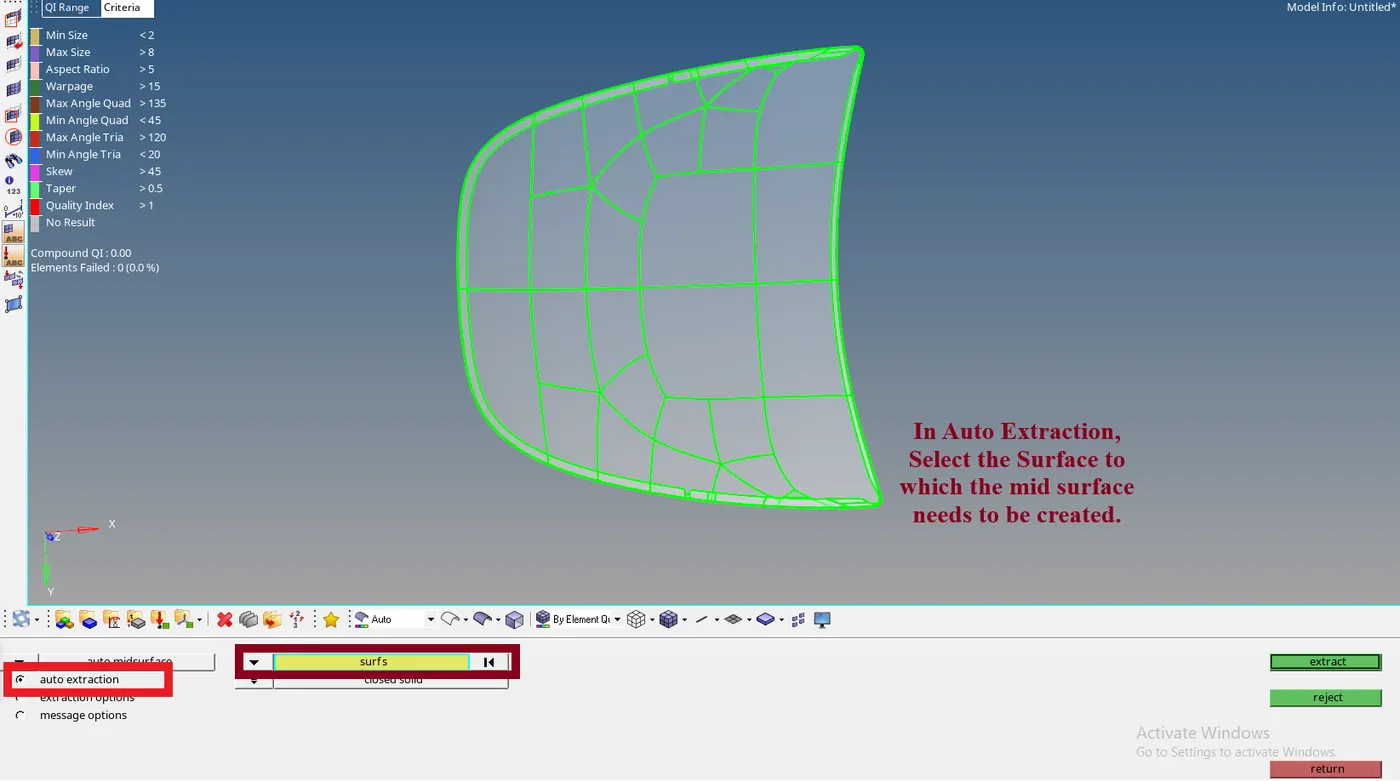
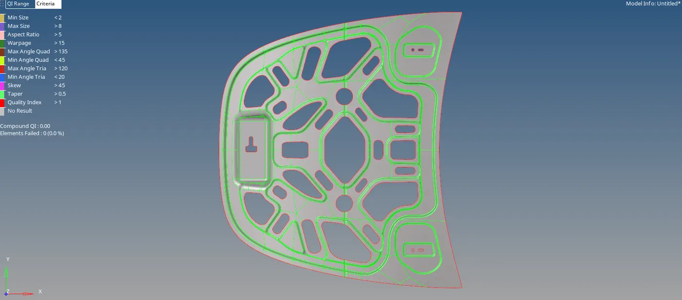
- For the Mid Surface of the hood part, auto mid surfacing is performed.
- In Geometry Tab, Select Mid surface >> Select Surfs option >> Select the Surface >> Click Extract.
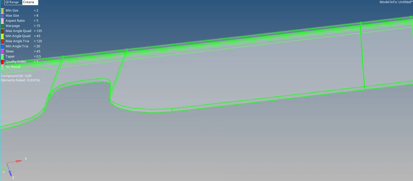
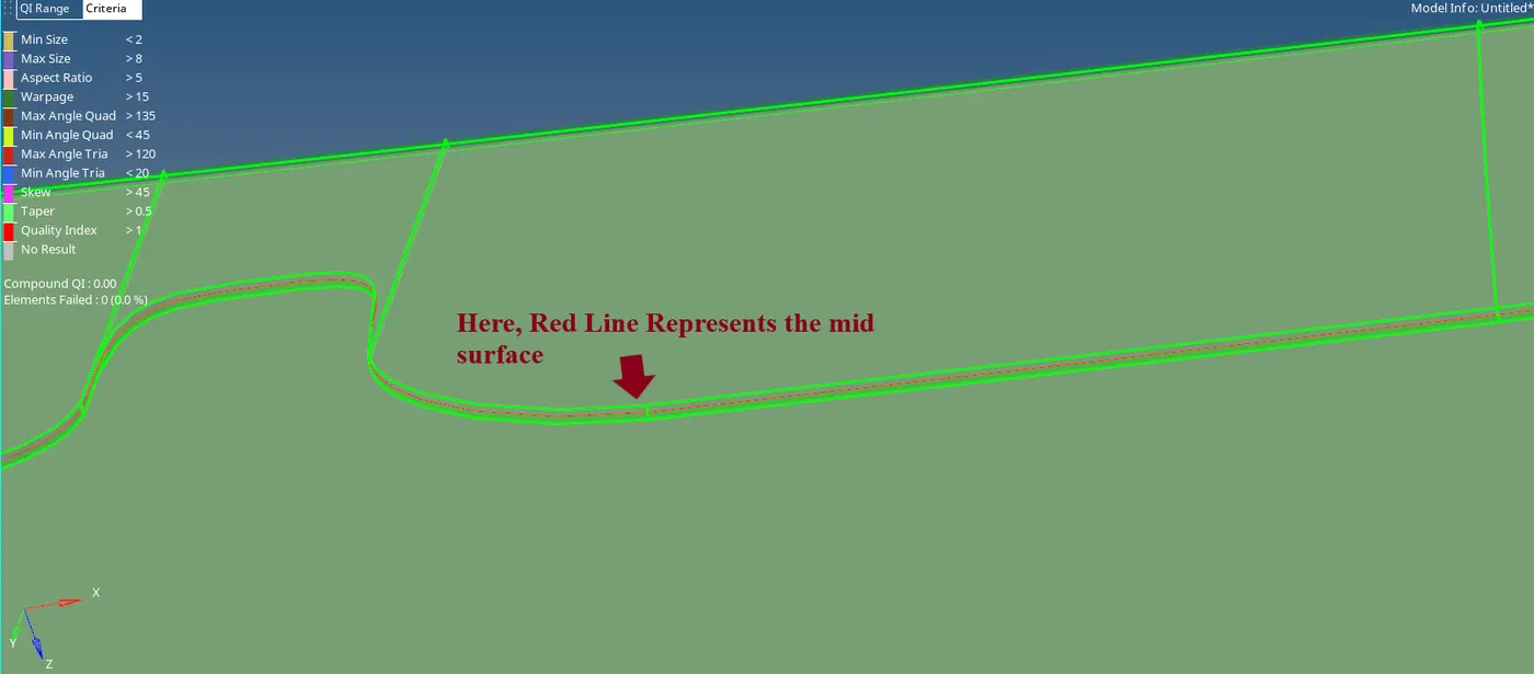
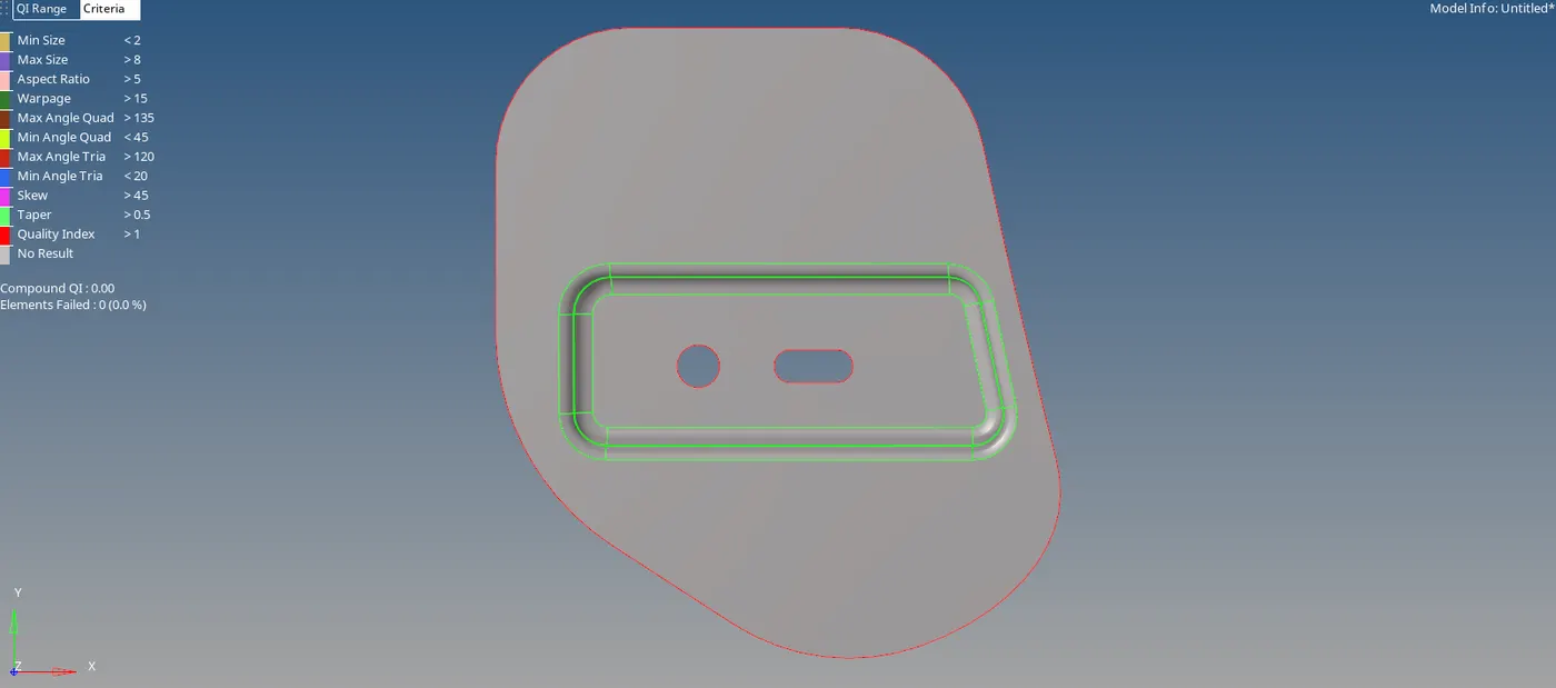
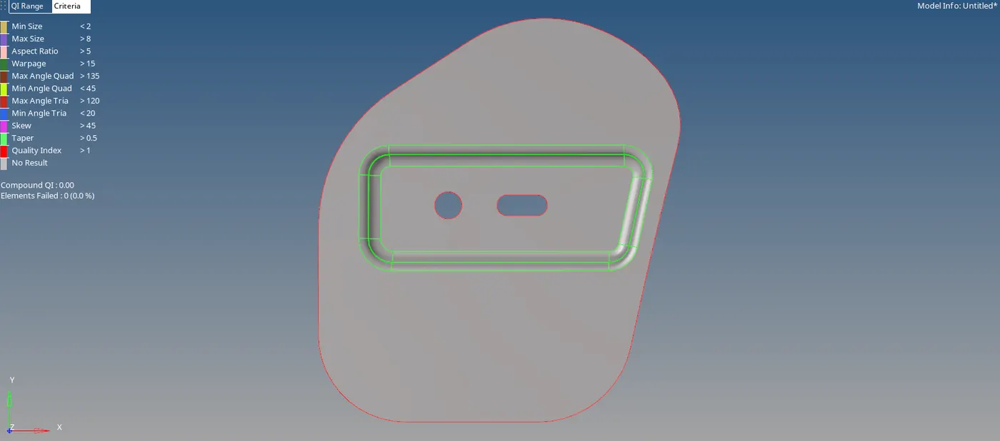
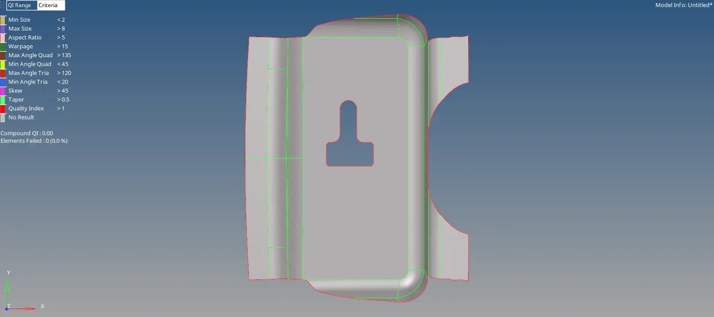
- The Mid surface is created.
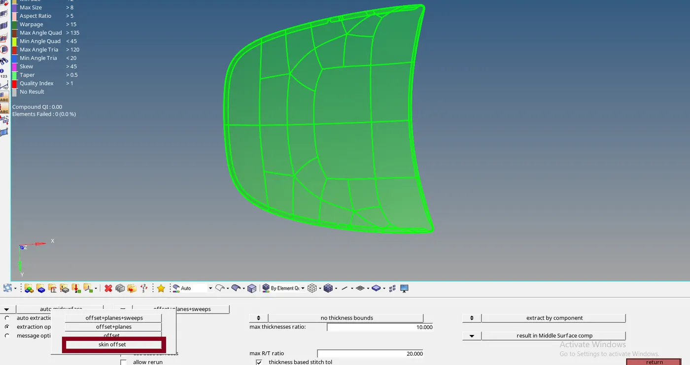
- In the mid surface option, select the Extraction options and select the skin offset option.
- Other mid surfaced components are as follows.
- Giving the Quality Criteria:
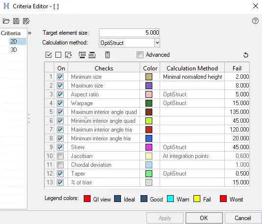
- Quality Criteria for this model are given.
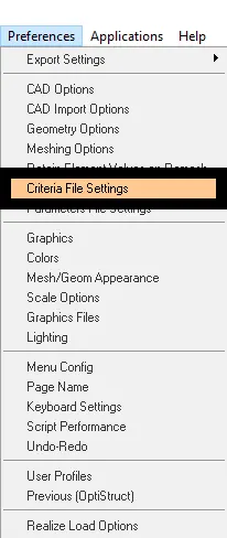
- In status bar, Preferences >> Click Criteria File Setting >> Give the criteria >> Click Apply >> Click OK.
- Generating the mesh:
- The mesh is to be created on the mid surface so that the main part doesn’t get affected.
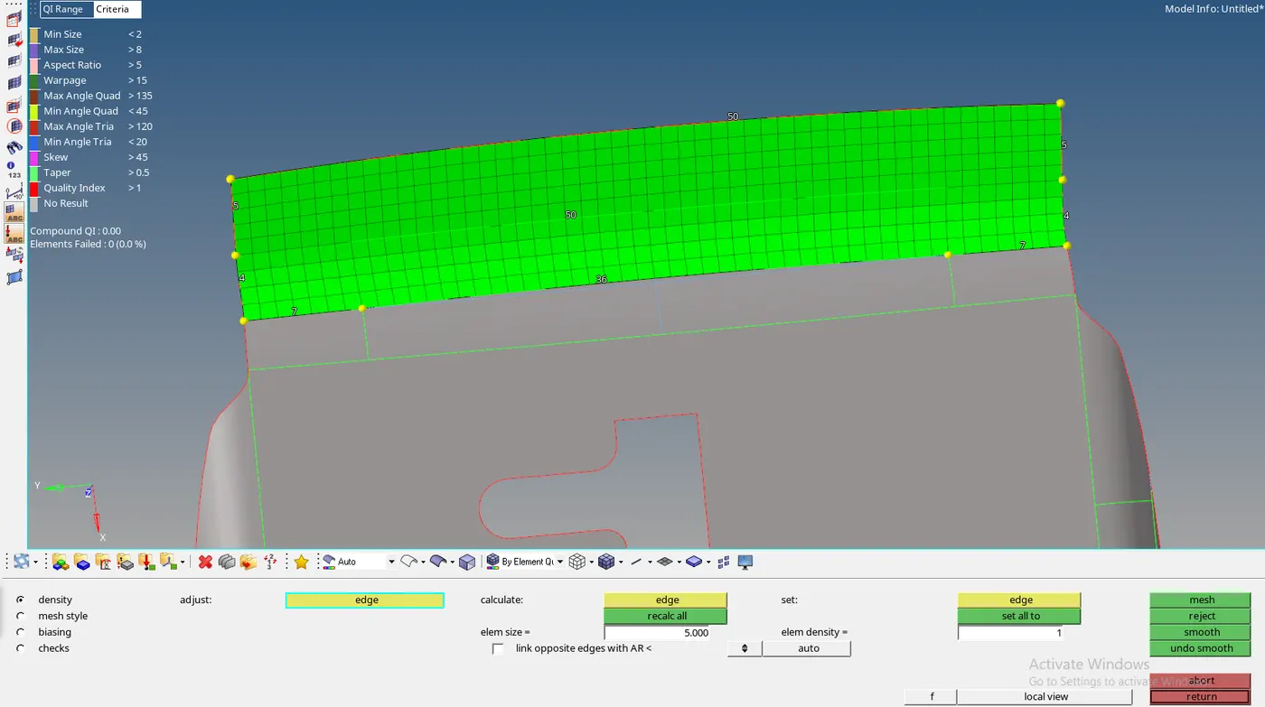
- To mesh the component, Go to 2D Tab, Select Auto meshing >> select surfs >> give Element size >> Select Mesh Type as mixed >> Click Mesh.

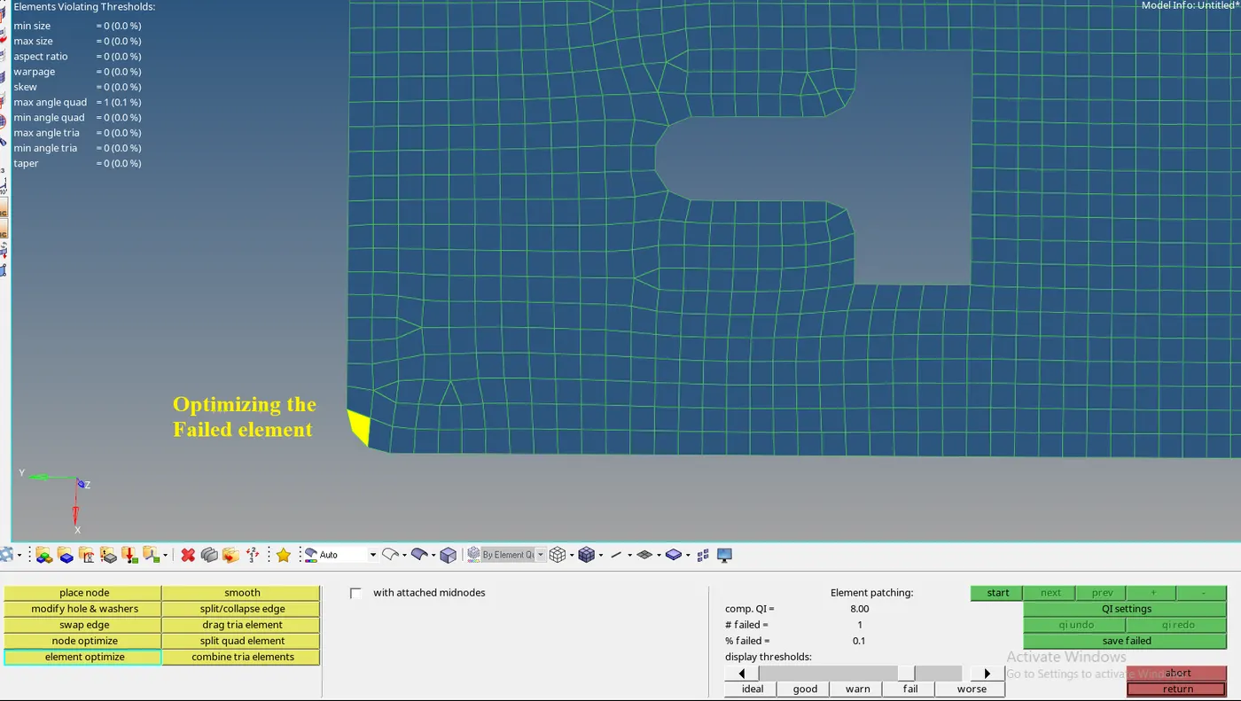
- To reconfigure the mesh select quality index in the 2D tab, Select Cleanup tools >> The Tools are used to modify the mesh to get the proper mesh.


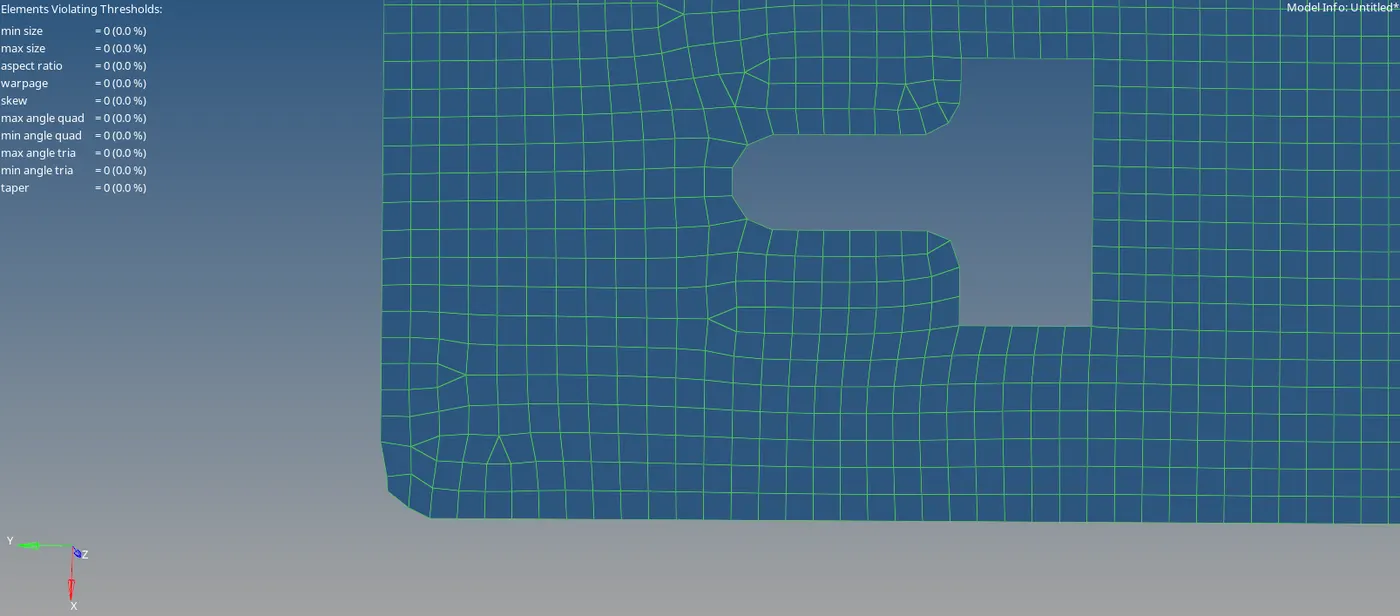
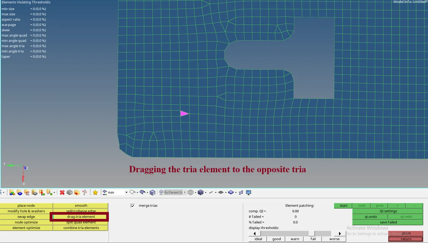
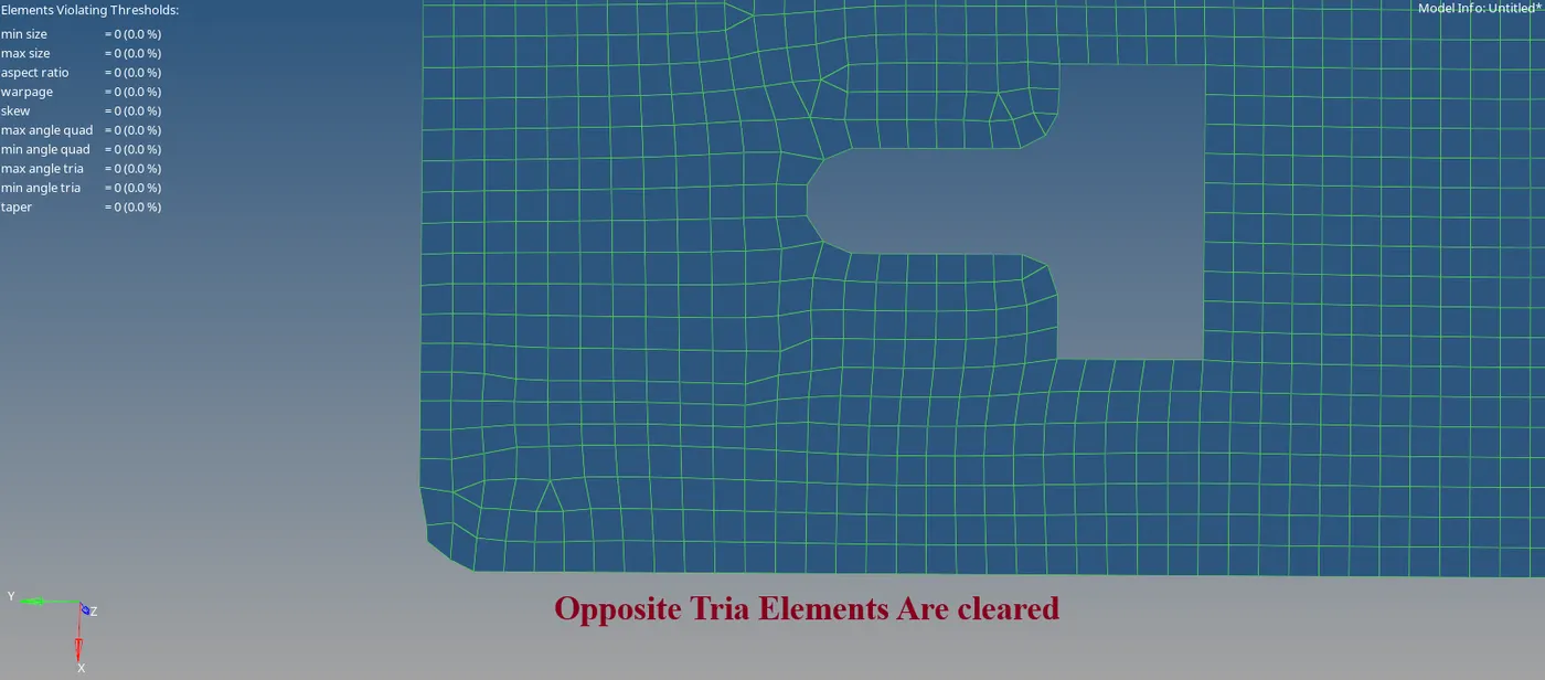
- Click F7 to align the nodes. Select the nodes of 1stend and 2nd end and then select the nodes.
- To Project the meshed lines to the Feature line, the Project tool is used. Go to the Tools Tab >> Select Project >> Select To line >> Select the nodes >> Select the lines >> Click Project.
- The Reflect is used to mirror the component. Go to the Tools Tab >> Select reflect >> Select the elements >> Select N1, N2, N3 and Base points >> Click reflect.

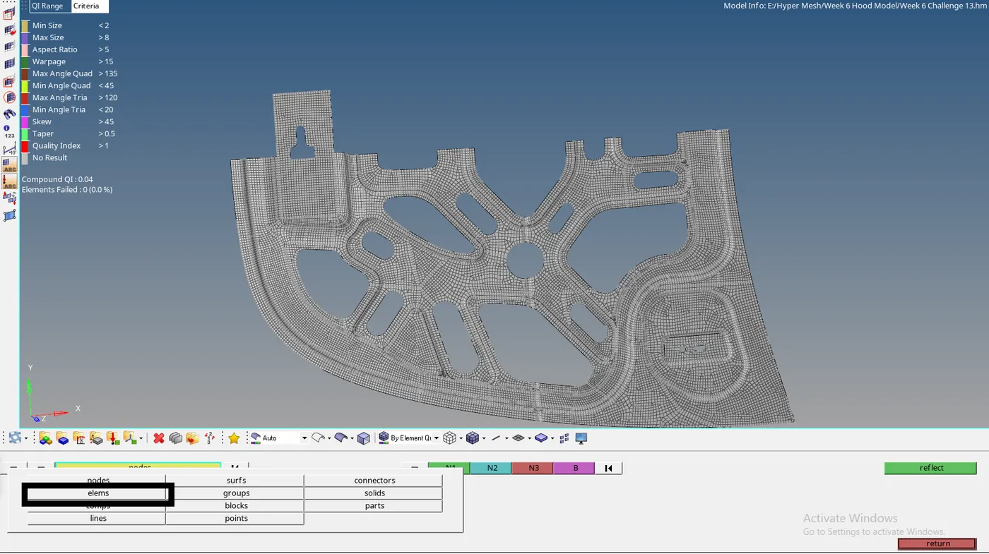
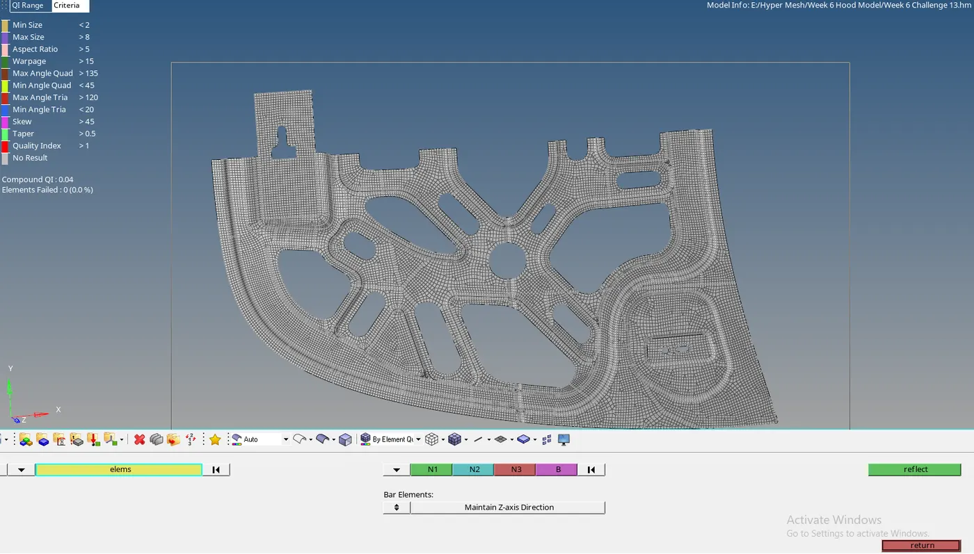
- Click on the elems option once to duplicate the part.
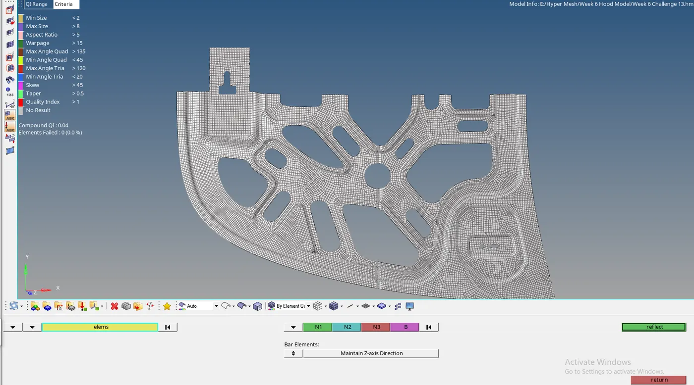


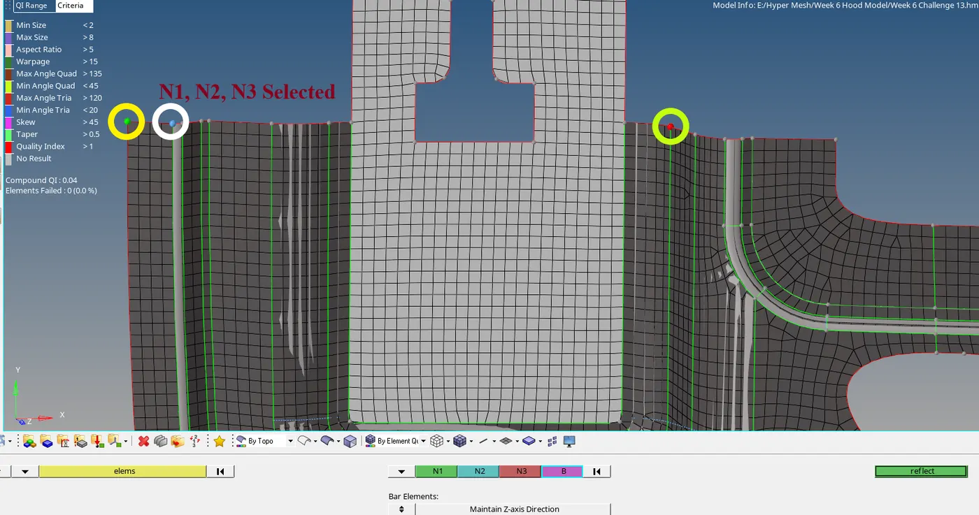
- N1, N2, N3, and B are selected. Where N1, N2, and N3 are the orientations and B is the base element.
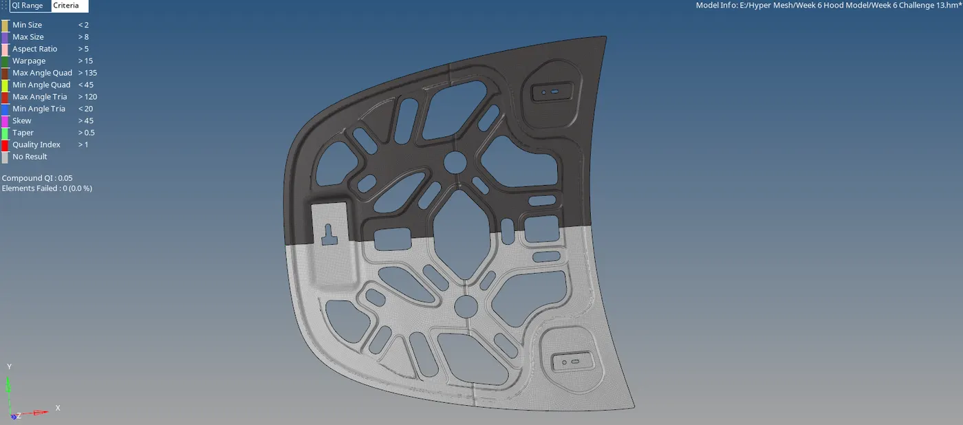
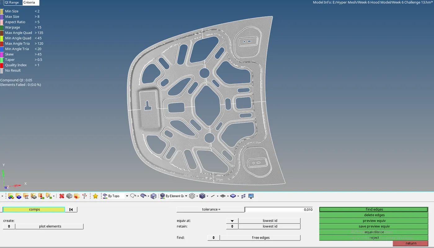
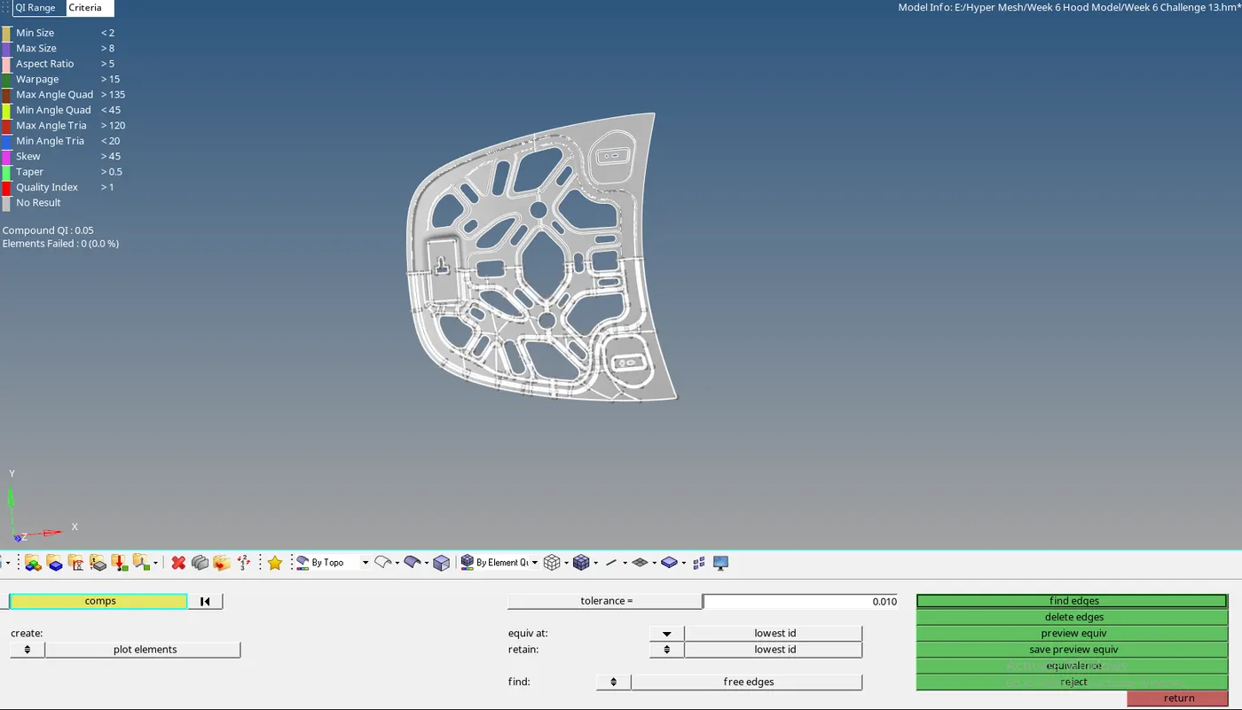
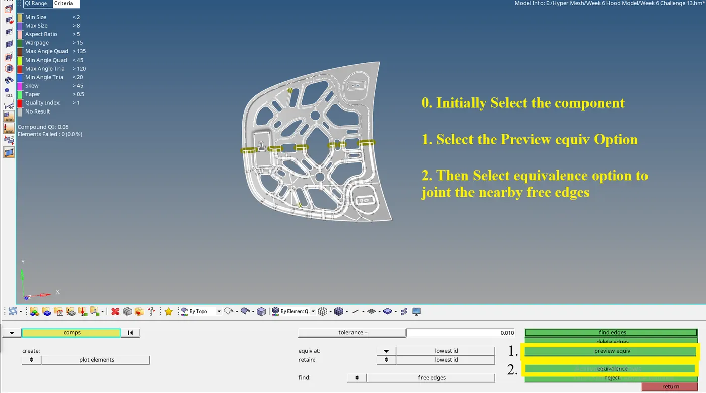
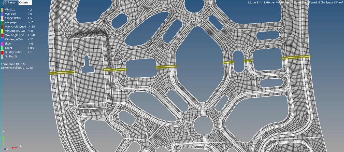
- After reflect is completed, the free edges are checked to see if there are any free edges. Go to the Tool Bar, Select reflect >> Select comps >> Find edges. Then to create the equivalence to the component, Select the Component >> Click Preview Equiv >> click equivalence.

Tools Used:
Reflect:
The reflect option is used to mirror the component. It is mostly used for the symmetrical structures for which only one half of the part can be mesh and reflect is done to complete the model.
Quality Criteria:
The Quality Criteria are the conditions in which the mesh should be present. If the conditions are not met the component fails which results in the Quality failure of the model. and the design change or the DE-featuring must be done to make the component meet the Quality criteria.
Edges:
The Edges tool is used to check for the free edges and to solve them if any collapsed edges are present. If any two surfaces are joined together by are not connected properly equivalence option is used to join them.
Results:
The mesh is created for the given Hood Model. The mid surfacing and mesh part is created clearly.
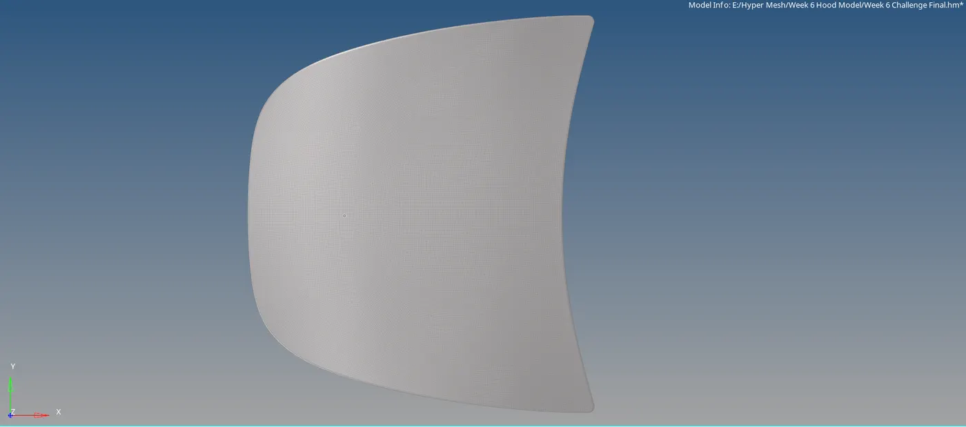
Outer Hood Part:
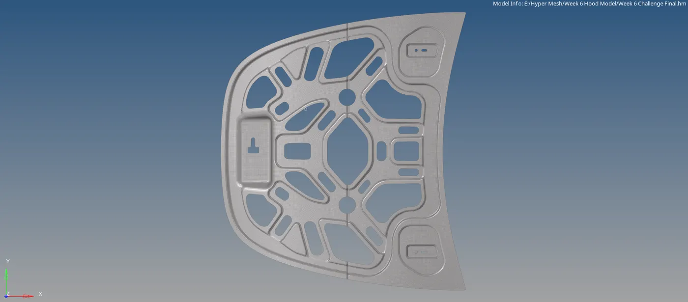
Inner Hood Part:
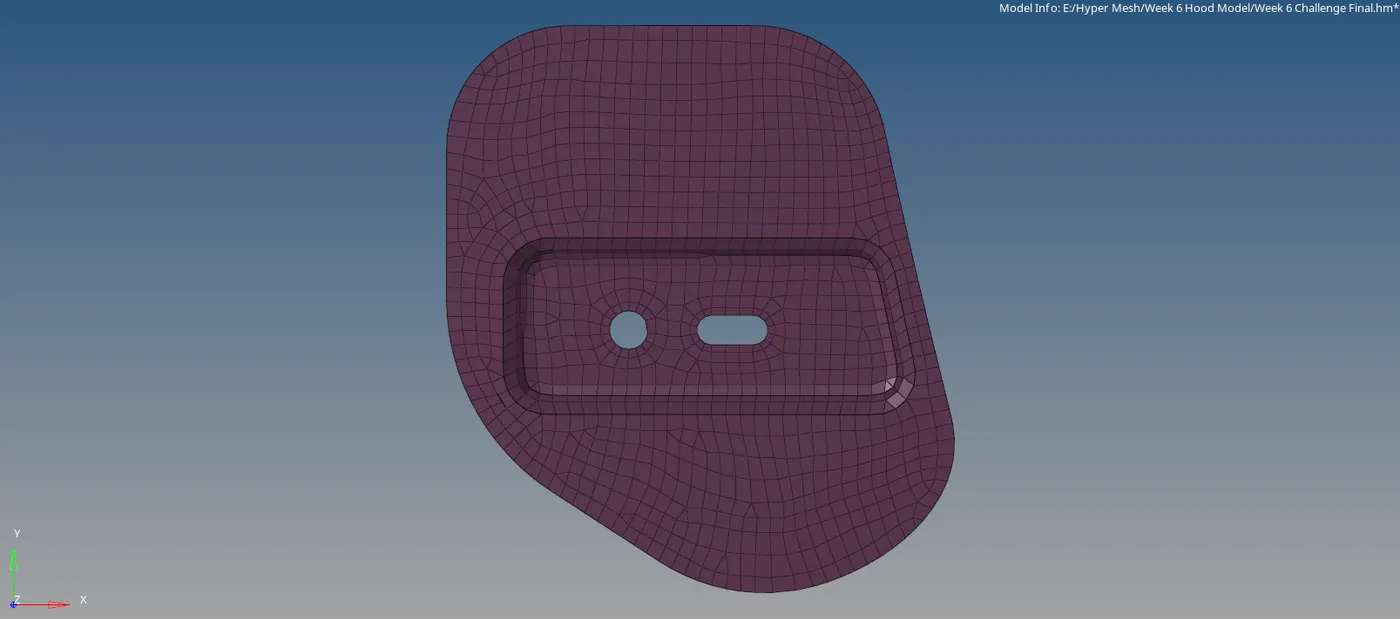
Hinge Part 1 Meshed Part:
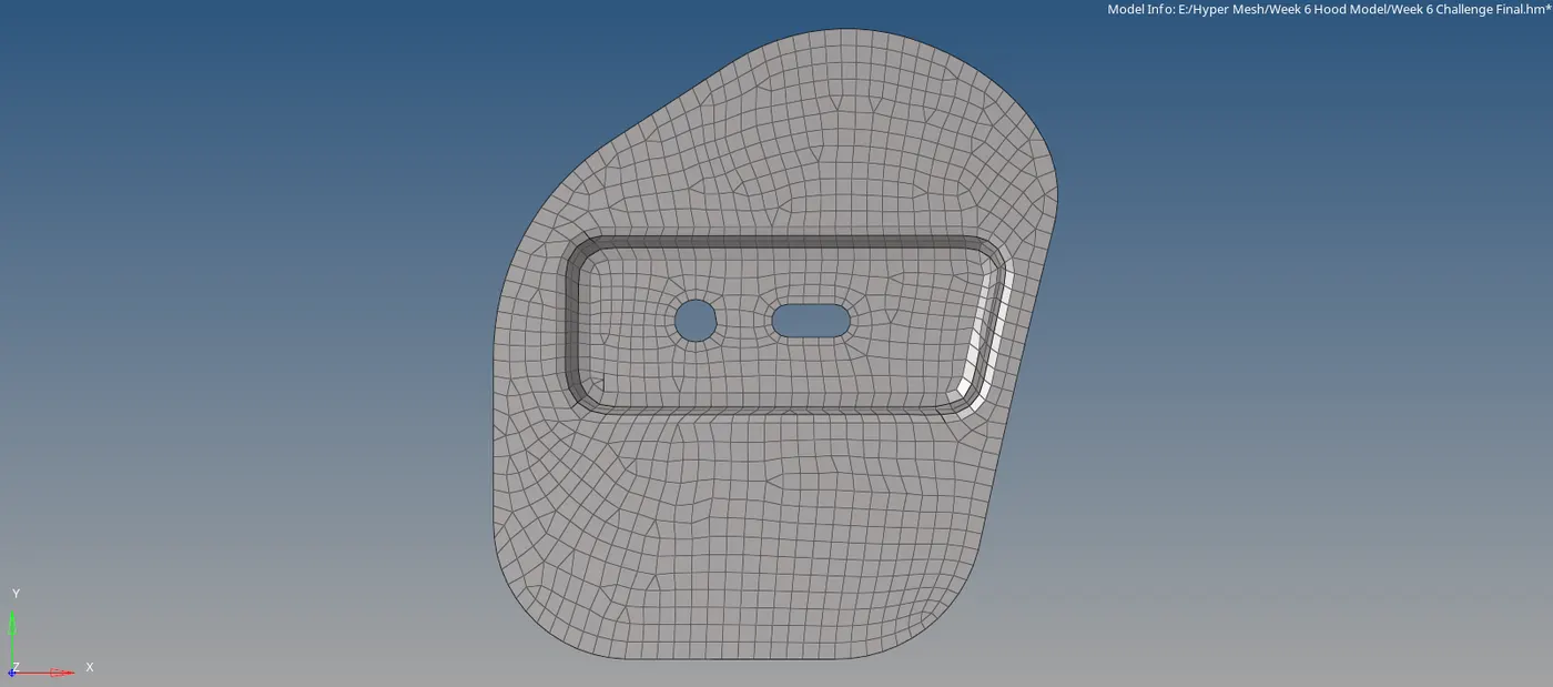
Hinge Part 2 Meshed Part:
Latch Meshed Part:
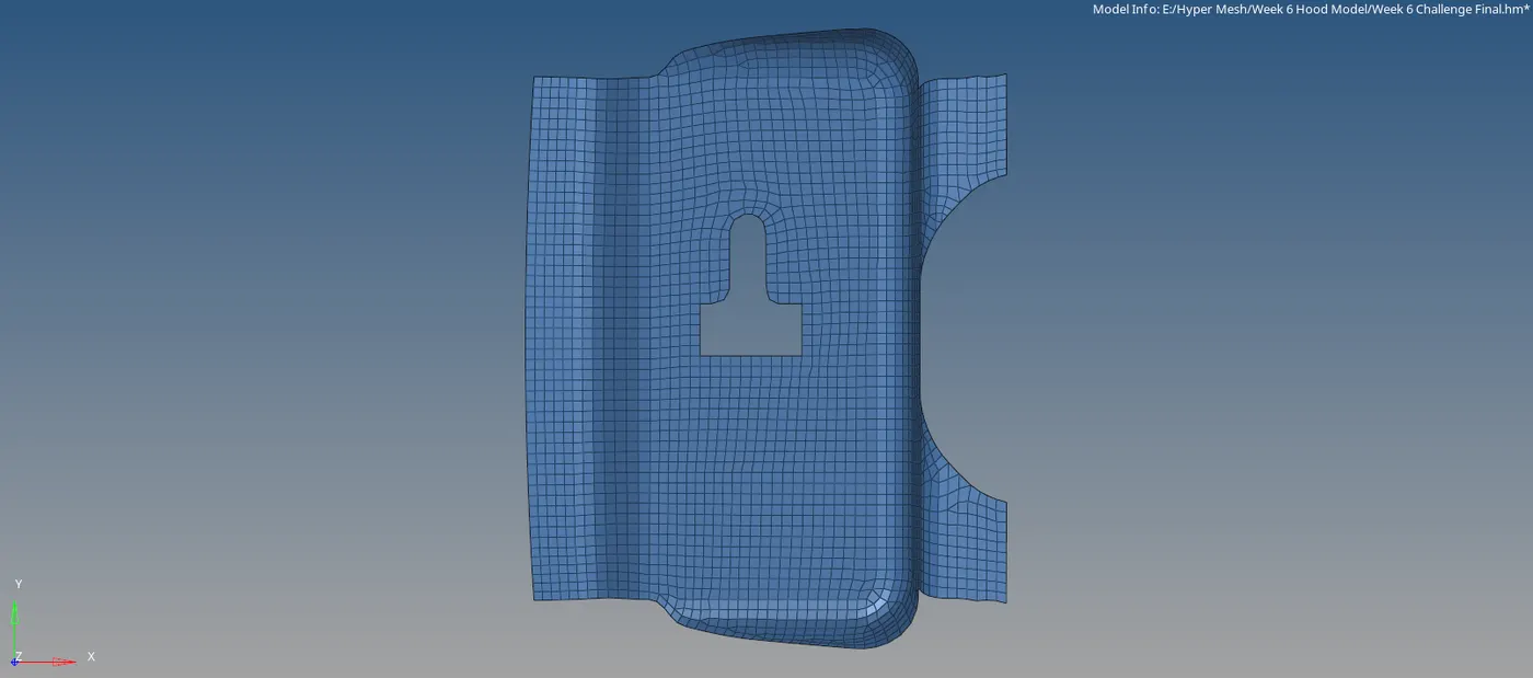
Final Meshed component:
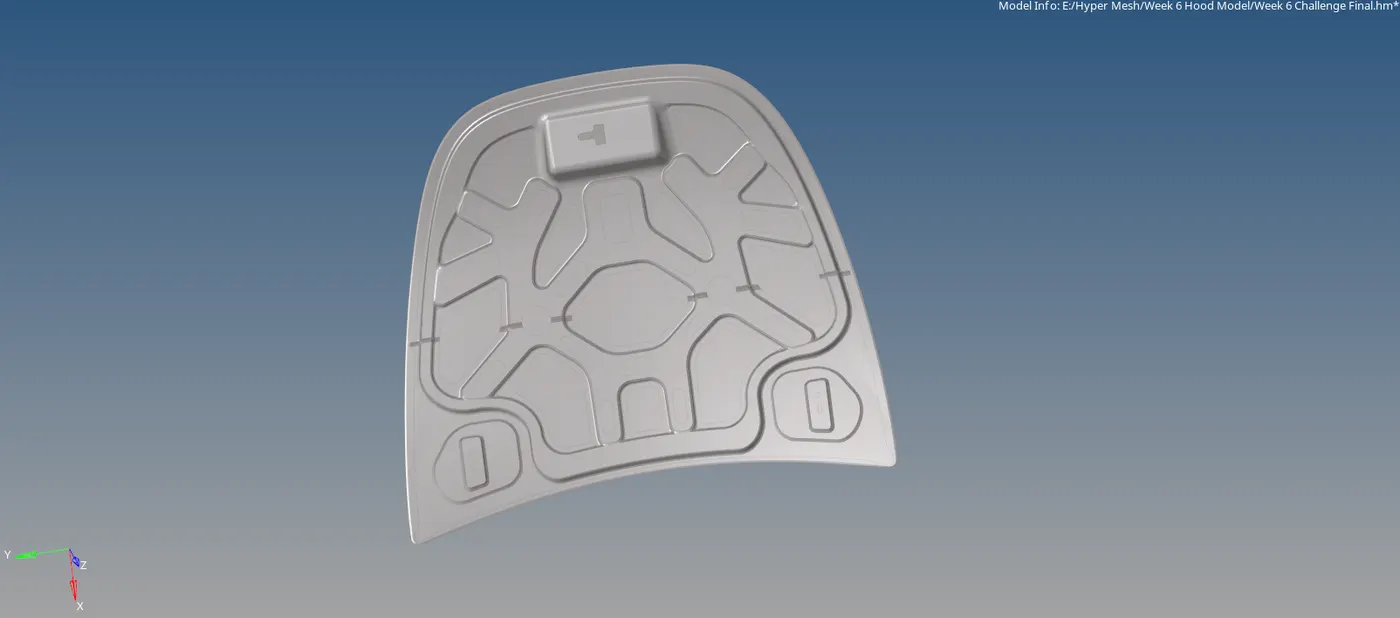
Learning Outcomes:
Each chapter teaches a new lesson, which is important to learn to achieve perfection. The learning outcomes from this model.
- Learned how to create the Mid Surface
- Learned how to create a mesh.
- Learned how to generate a mesh properly.
Links:
Google Drive Link: Week 6 Hood Model