Week 6- Challenge
Aim :
2D Meshing the hood component in HYPERWORKS.
Objective :
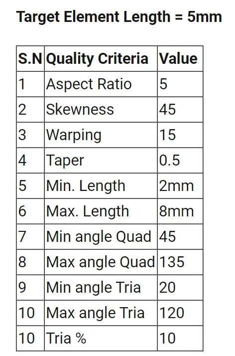
To extract the mid surface of the given HOOD component and perform the meshing using the below quality criteria.
Procedure :
Step1 : Importing the CAD model of HOOD to workspace
The current hood model is segregated into 4 parts as
- Hinge- 2
- Latch
- Outer hood
- Inner hood
So meshing and surface extraction will be done part by part for ease.
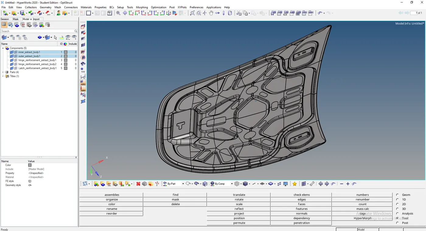
Fig- Hood cad model imported into Hyperworks workspace
Step 2 : Outer hood mid extraction and geometrical clean up :
Hood basically has an outer in which the inner hood body is fitted with a hemming process. Outer hood is a plane component with edges as turned with hemming.
Surface extraction :
The outer hood is a simple sheet metal part for which automatic surface extraction can be used. To do that
Geometry >mid surface > surfs> select the surface
We have a number of methods for surface extraction and all work the best in this simple component. But we need to compare the mid surface with the parent model to check for the surface accuracy.
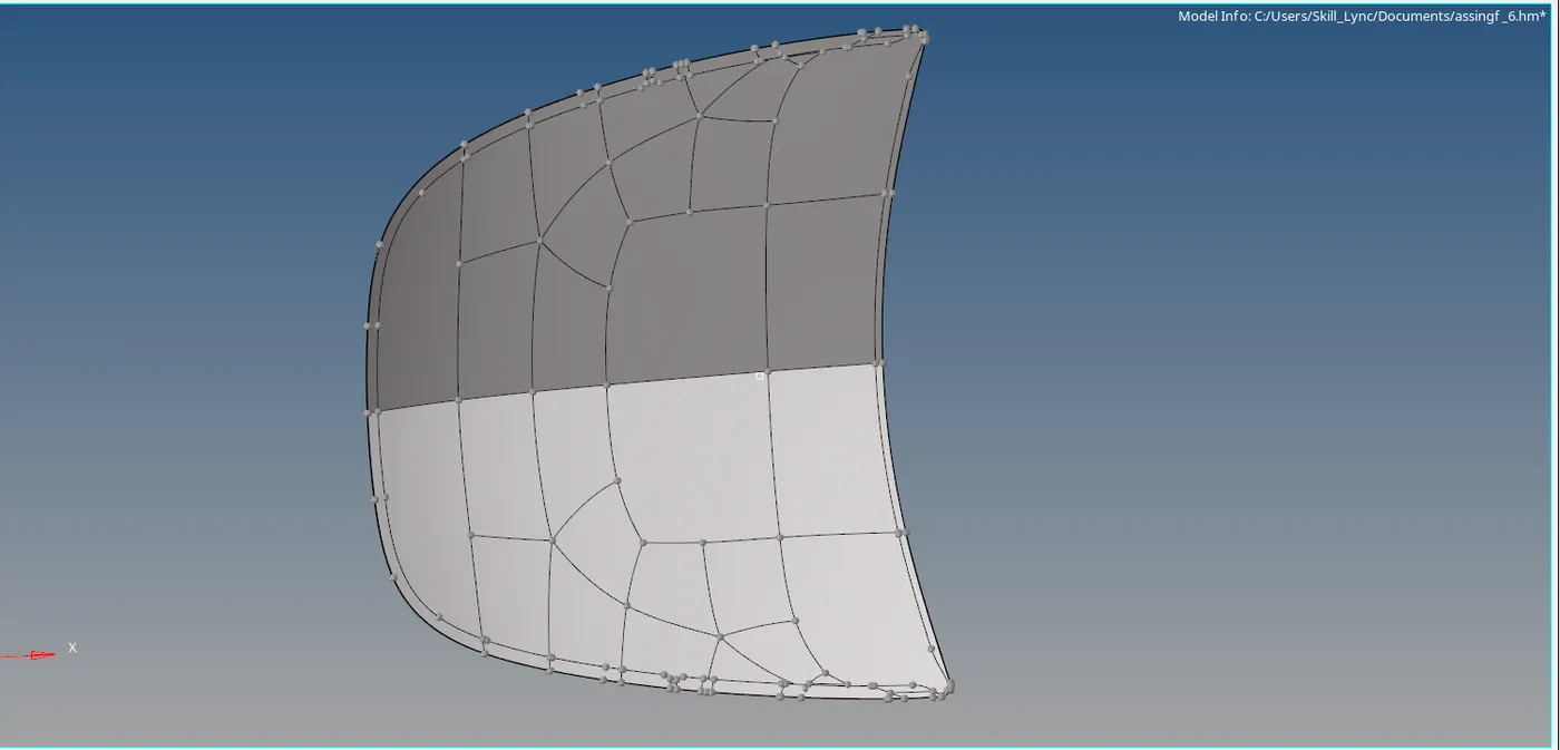
Fig- Mid surface for outer hood using automatic extraction
Cutting hood into half :
The outer hood is a symmetrical component that can be cut into half. The purpose of removing the half part is that we can meshed or work on the half part and then reflect and duplicate it to get the other part and patch it accordingly. All these processes help in saving the time to do meshing and solving the failed elements.
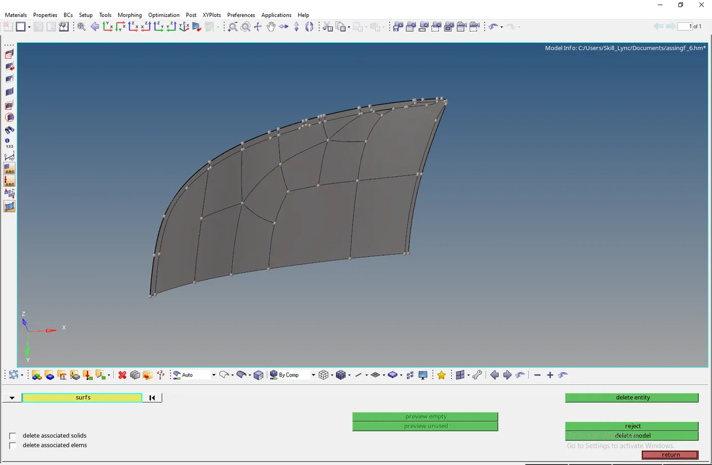
Fig- Hood cutted to half
Geometrical clean up :
Here the only geometrical clean up needed is to remove the unnecessary curved lines on the surface and recreate the lines that will be more like square shapes to get more number quad elements.
Also the hemming part is defeatured in such a way that only the peak portion of the fillet is needed to capture while meshing. This is done to avoid the failing of elements in that region as its has below less measured value than the minimum element size .
Since all these clean up cannot be carried by automatic clean up , we are using manual tools to clean up
Geometry >quick edit tools
Some of the tools used here are
- Toggle - to suppressed and unsuppressed the lines
- Surf line by node/line - to create construction lines on the surface
- Add /remove the points - to remove the extra points from the lines or edges
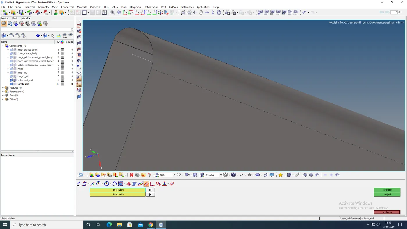
Fig- Capturing only peak of the fillet.
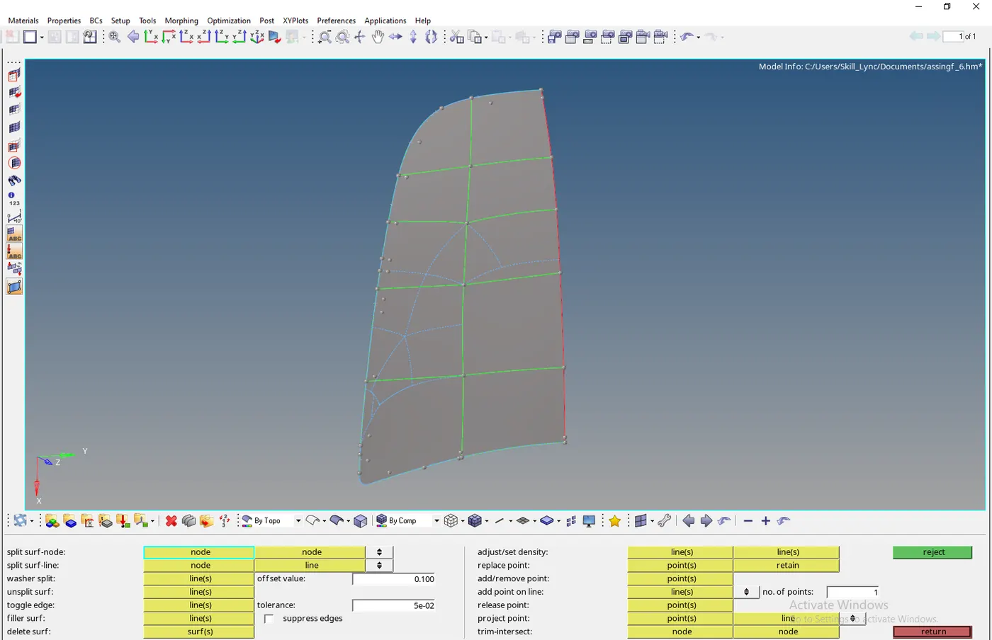
Fig- Box shapes construction lines created using quick edit tools.
Step 3 : Meshing the outer hood
After the clean up is done , the next step is meshing the component with the use of quad and tria elements. While doing the meshing the important points to followed is
- No opposite tria present near to each other
- No rotating quads
- No tria near the free edges
- Mesh should be good and uniform pattern
2D meshing is opted for the sheet metal components where the thickness is less as compared to the span length(thickness upto 5-6mm are meshed with 2D ).The measured thickness here is around 1.2mm for the component.
After making the necessary changes to the component, the next step is the meshing the part in an appropriate way.
To do the meshing
2D>surf (select the surface )> element size as 5
Before starting the meshing see that all the criteria values are correctly feeded and switch the view mode to by element quality( shows the number of failed elements on the workspace).
Here the meshing is approached region wise i.e meshed in one area, clearing that area and then progressing to other areas.
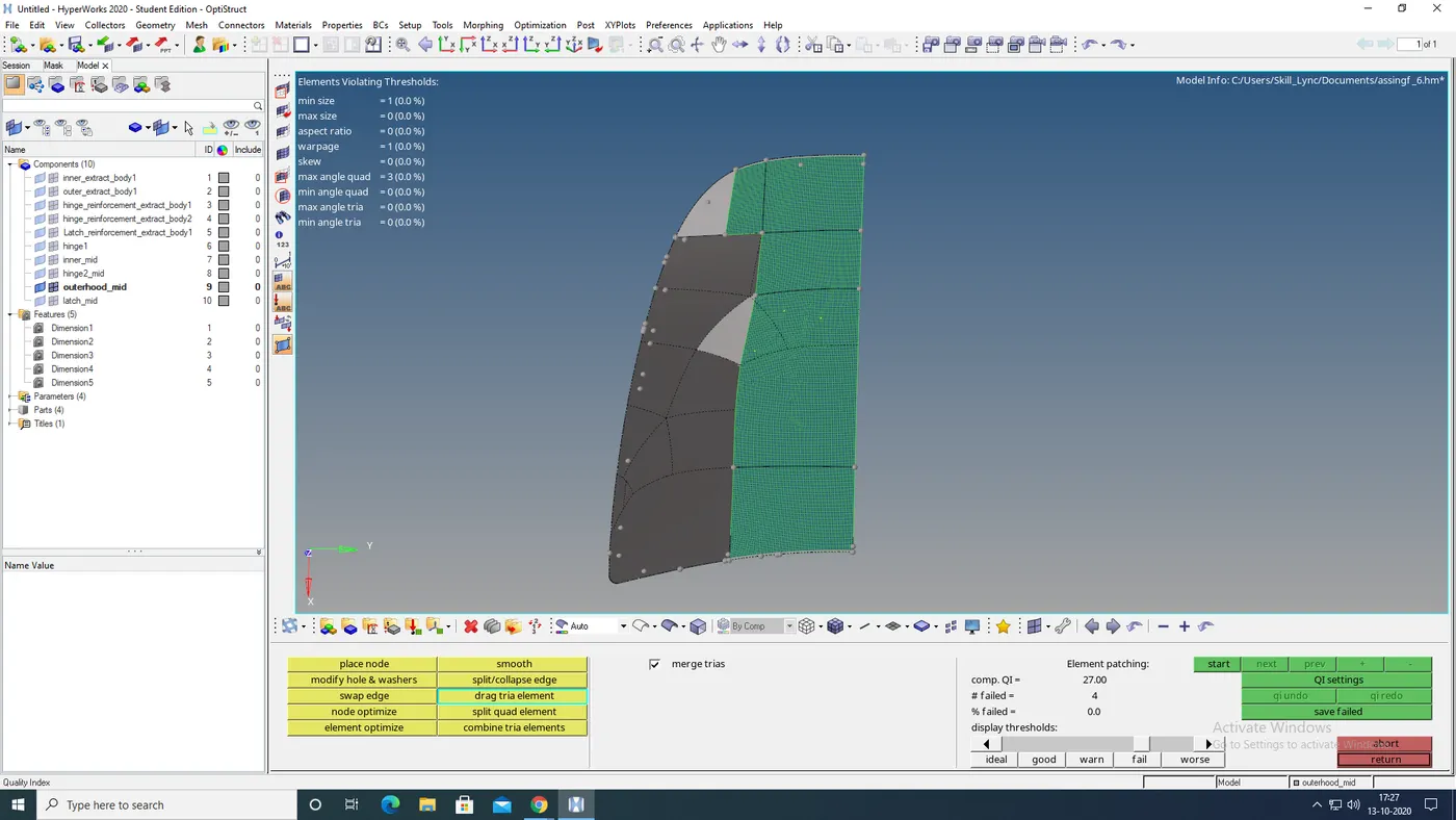
Fig- Meshing carried out region wise.
Tools used to solve the failed elements.
- Drag
- Split
- Smooth
- Replace
- Split
- Translate
- Swap
- Place node
For ex . drag is used to drag or move the tria on over the meshing plane to join or combine with opposite tria to form a quad element .
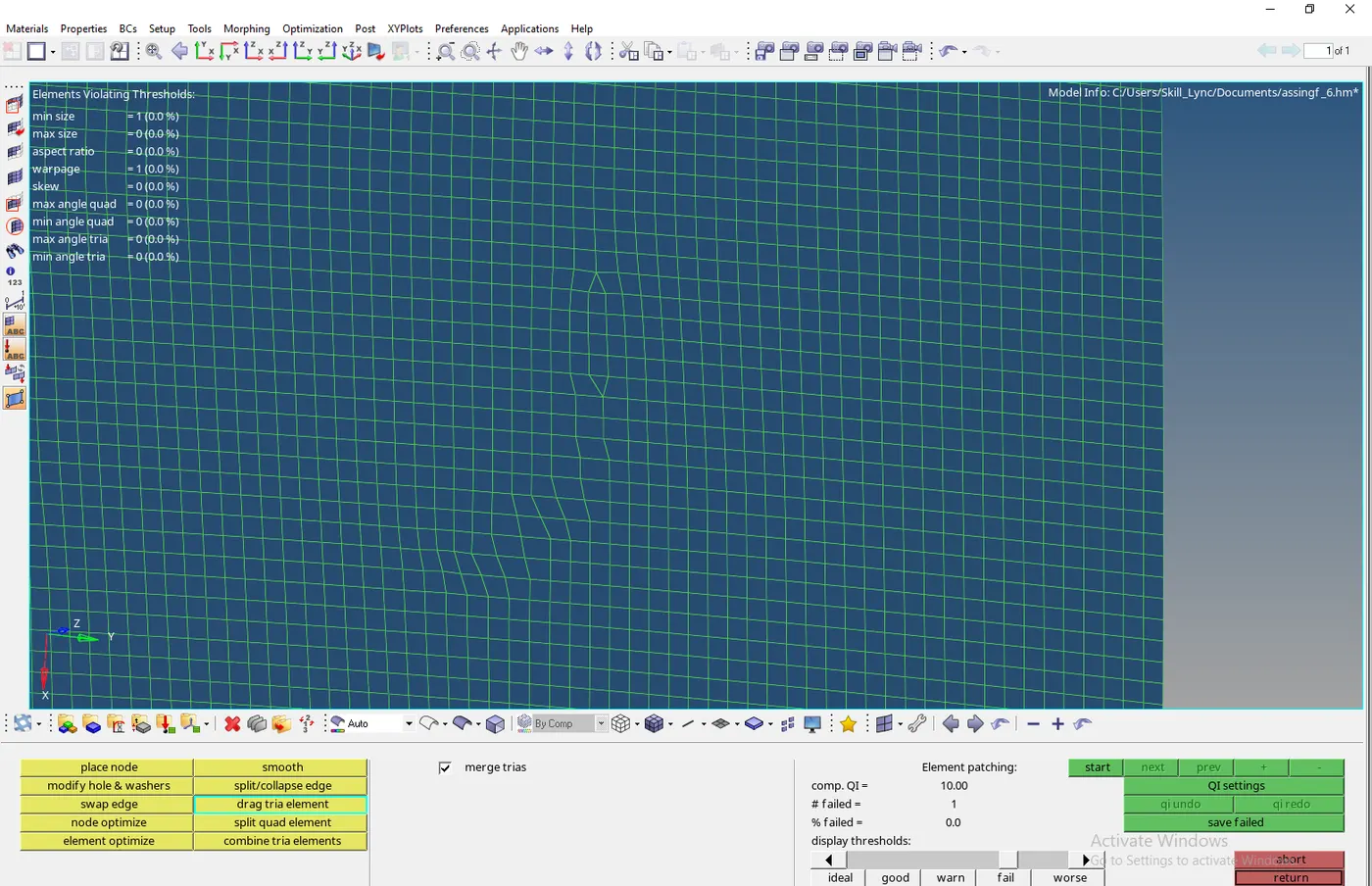
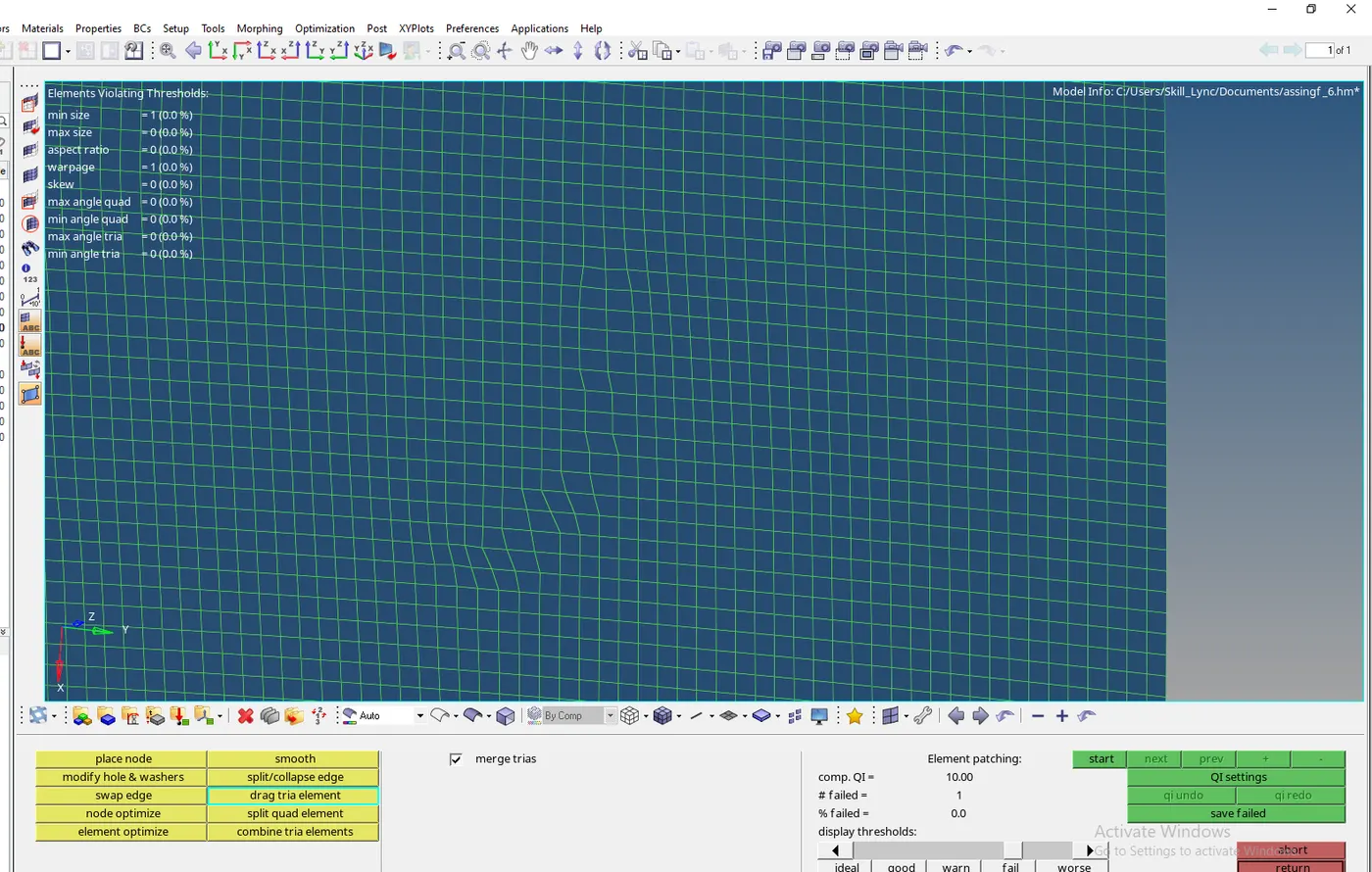
Fig- opposite tria eliminated usigh the drag tool(left- opposite tria , right- tria formed to quad)
Step 4 :Checking for the free edges
Checking for free edges means to ensure that all the elements are connected to each other properly i.e with no gaps. Generally the free edges are formed between the elements where the geometry or the plane changes.
To check for the free edges
Tools > edges > elements (select the elements by displayed ) > find edges
The free edges are shown by the red colour lines when switched to the component view mode.
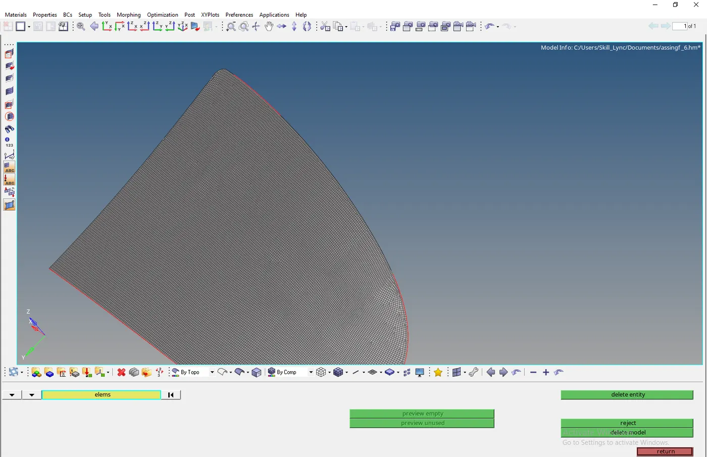
Fig- Free edges present as shown by the red lines.
Step 5 : Solving the free edges
To solve the free edges we make use of the replace tool
Tools > replace
All the elements ends are connected to each other using the replace tools to make the meshing free from gaps and free edges.
Step 6- Reflecting and patching up the outer hood
Since we only worked on the half part of the hood , we can get the other half of the hood by using the reflect option to get the complete hood.
Tools >reflect > elements > duplicate > node selection > reflect
It's important to first duplicate the elements in order to get the reflection of the hood. Also see the current component is the outer hood only.
Equivalence :
Now after reflecting the hood , both sides need to be joined at the symmetry line. This patching the two mesh sides can be done by using the edges option.
Tools>edges >elements> select the elements >preview equivalence>equivalence
After previewing the equivalence , the small gaps between the elements are highlighted by the green dots which are fixed by using equivalence.
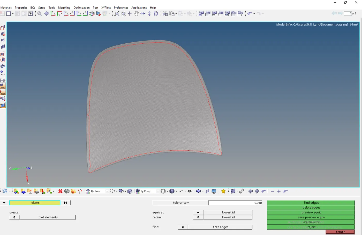
Fig- The outer hood is reflected and joined with no free edges.
Step 7: Hinge component mid surface extraction
Hinge component is activated from the TAB bar by turning off the rest of components. Also here there are 2 hinges but we will be working on only one hinge other hinge can be bought by reflection method.
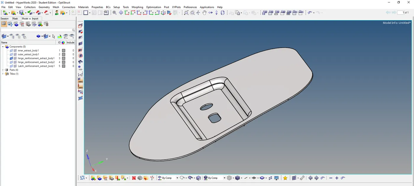
Fig- hinge of the hood
Surface extraction :
The hinge is a simple sheet metal part for which automatic surface extraction can be used. To do that
Geometry >mid surface > surfs> select the surface
We have a number of methods for surface extraction and all work the best in this simple component. But we need to compare the mid surface with the parent model to check for the surface accuracy.
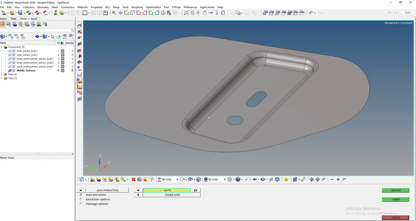
Fig- Hinge mid surface extracted.
Geometrical clean up :
Geometric clean up involves preparing the mid surface for the meshing. Clean up checks and adjust the lines, edges and holes so that minimum element criteria is met. One important feature of the automatic clean up is that it provides the washer split around the holes in order to avoid the trais.
Geometry > autocleanup> element size is 5
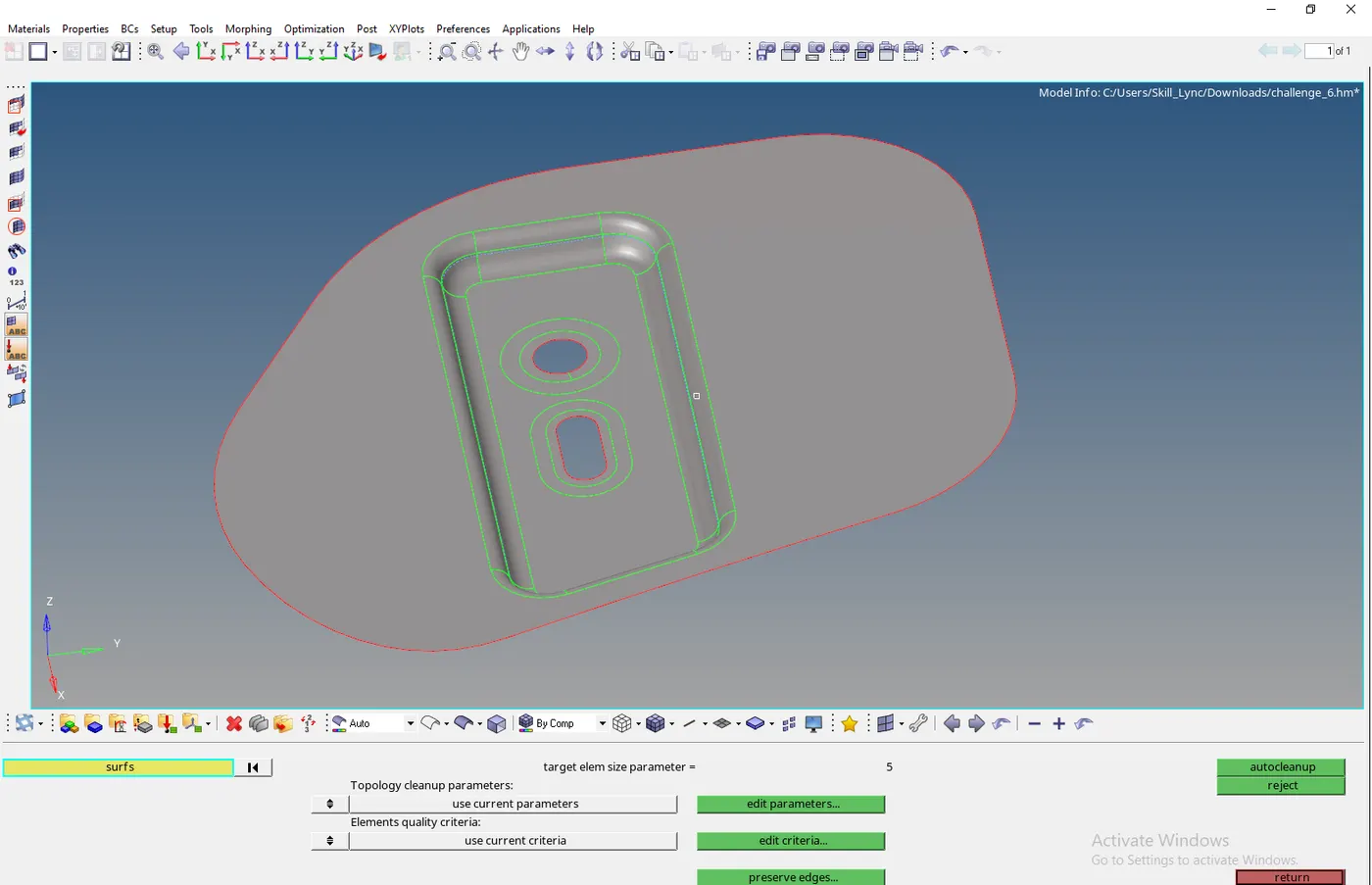
Fig- Hinge after autoclean up.
Before starting the meshing and cleaning up it is quite convenient to feed all the quality parameters into the tool. It is done so to save the time while checking mesh and to clean up the surfaces according to criteria.
Preferences >criteria file setting
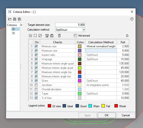
Fig- Inputting the quality criteria.
Step 8: Meshing the hinge component.
All processes involved in the outer hood are used here to solve and create the 2D meshing but the hinge being the small component the mesh is created automatically at once.
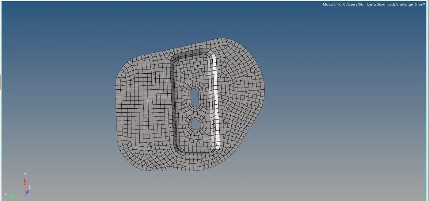
Fig- meshng of the hinge
Step 9 : Extracting the mid surface of latch and meshing
Latch is the catch which holds the hold of a car shut or where the hood handle is anchored to lock it.
Extracting the mid surface of the latch is the same as earlier using automatic mid surface extraction.
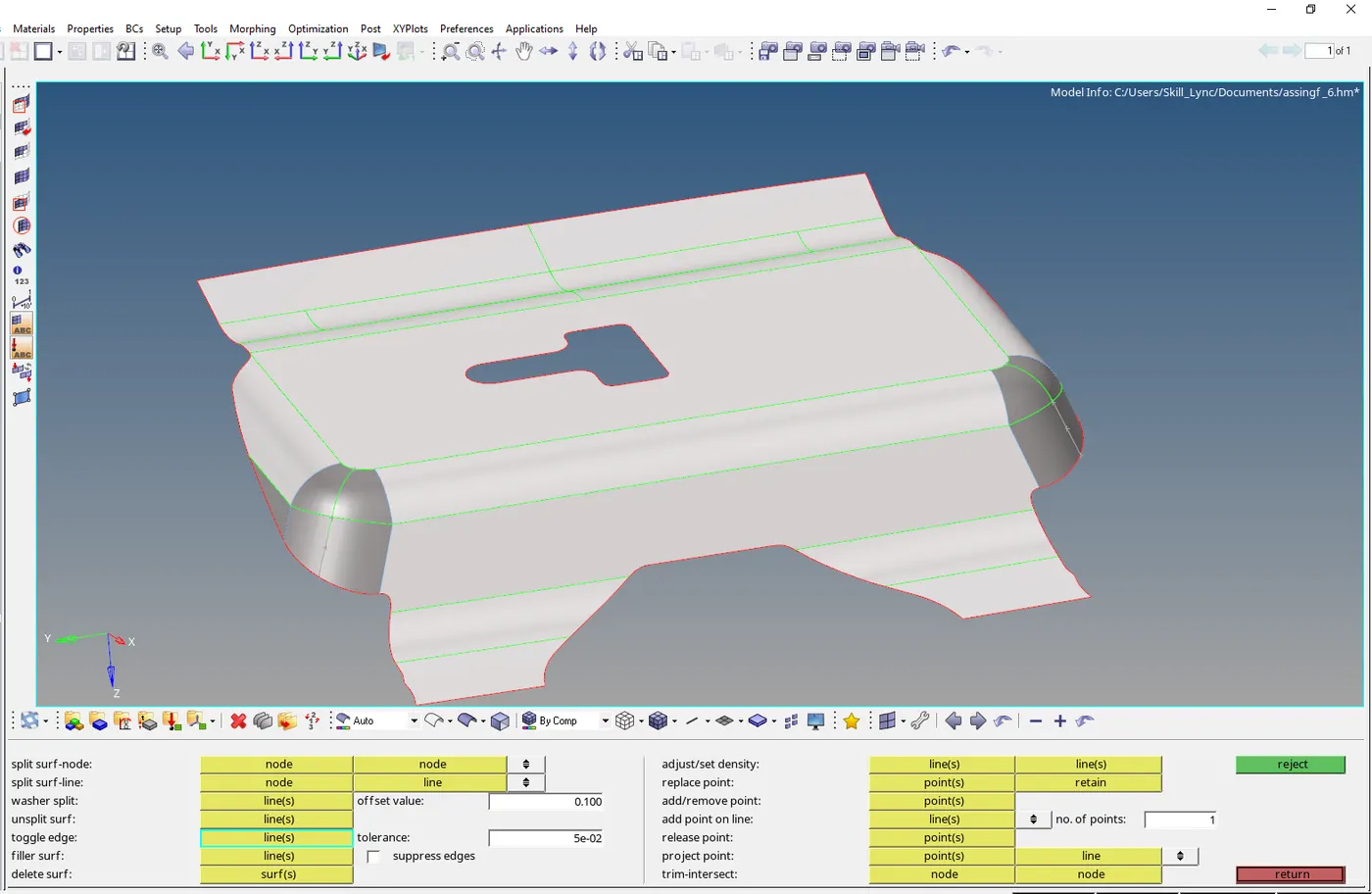
Fig- Midsurface of Latch
Meshing :
Meshing here is carried out using the mixed element i.e quad and tria with the average element size as 5. Meshing is approached by solving the failed elements using the above mentioned tools.
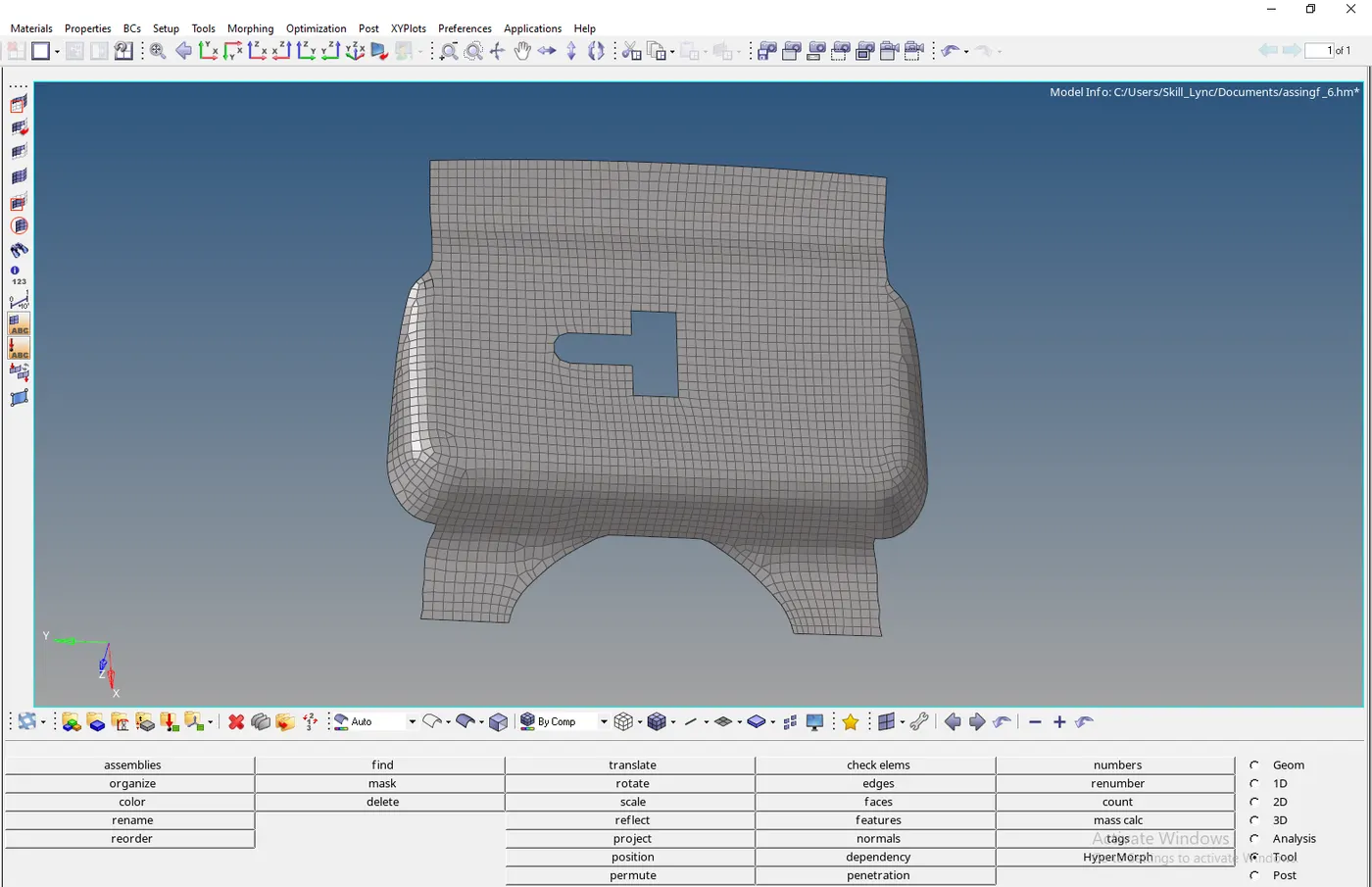
Fig - meshing of Latch.
Step 10 : Mid surface extraction of inner hood :
Using the automatic mid surface extraction , mid surface for the inner hood is also extracted accordingly.
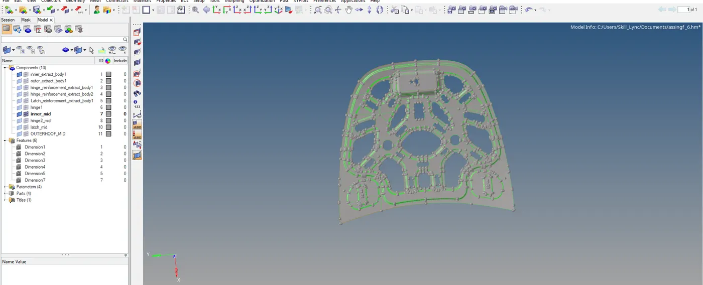
Fig - Inner hood mid surface.
For the inner hood we are again cutting the hood into half to save time since it is also somewhat symmetrical.
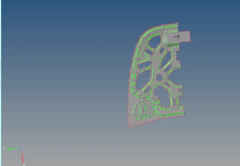
Fig - Inner hood cutted to half.
Step 11: Meshing and reflecting the outer hood
Like the outer hood , the inner hood is also meshed in region wise.
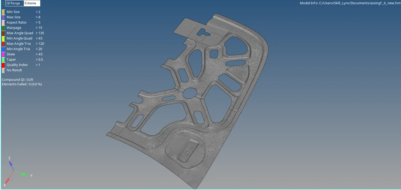
Fig- Inner hood Meshing .
Warpage error :
- Ideally all the nodes of a quadrilateral element should lie on the same plane but at curvatures and complicated geometry profiles it is not possible. "Measure of out of planeness of a Quadrilateral is Warping Factor or Warping Angle".
- Warping calculation for triangular elements is not applicable, since three points define a plane, this check only applies to quads.
- It is defined as the angle between normals of two (triangular) planes formed by splitting the quad element along diagonals.
To solve the warpage angle error we make use of the translate tool
Tool > translate > select the node > choose the appropriate axis .
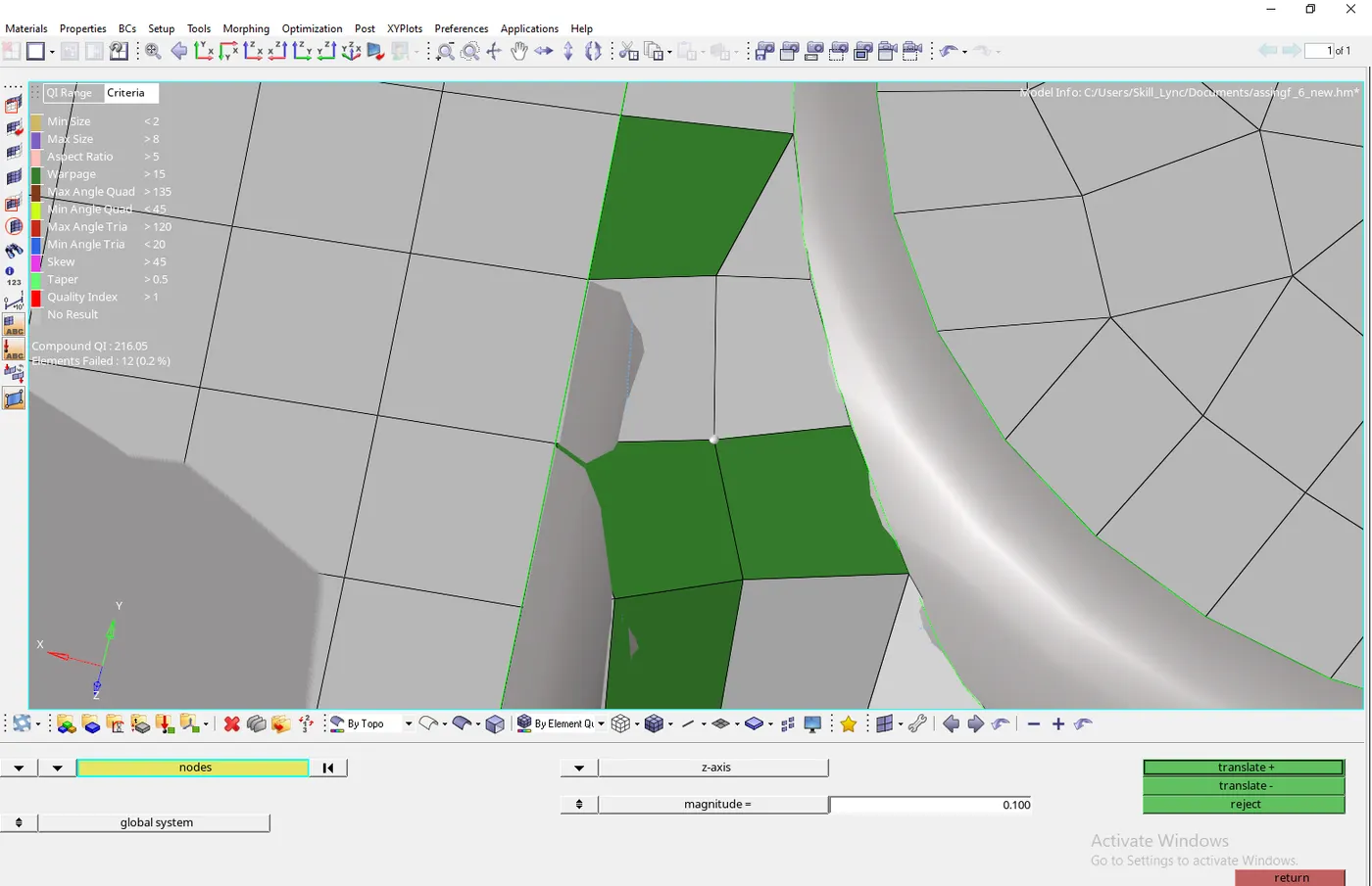
Fig- Warpage error (green elements) fixing using translate tool.
Results:
The final meshed components are shown below.
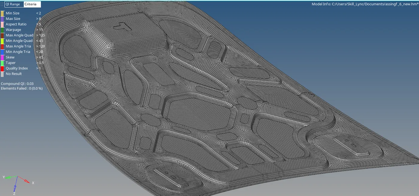
Fig- Final hood meshed components with no errors.
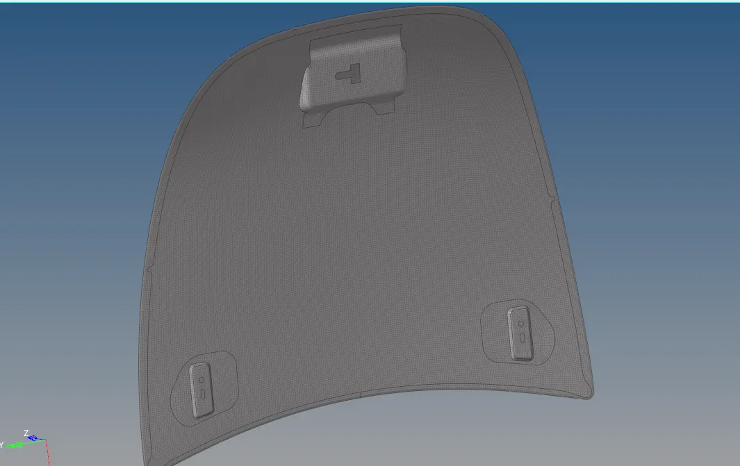
Fig- Meshed inner hood with 2 hinges and latch.
Conclusion:
All the components of the hood were successfully meshed with no faied elements. At cetain region especially curved raised or fillets area we have to compromised with the trai as the quad elements cannot capture the feature properlly. Moreover the quad will have warpage errors in the fillet region.
link for the meshed component: https://drive.google.com/drive/folders/12IZA7BKmJdCmcKbkigIkFnXdDwStUz33?usp=sharing