Week-6 Calculate the Stretch Ratio by comparing the ELFORM (-2,-1,1,2) with Ogden_Material Model.
AIM:
To create a block with the above mentioned dimension and use the ogden material properties into it , thus observing the behaviour of it under various element formulations given above.
Create appropriate boundary conditions to provide tensile motion to the cube.
Plot the graph between normal stress and stretch ratio.
PROCEDURE:
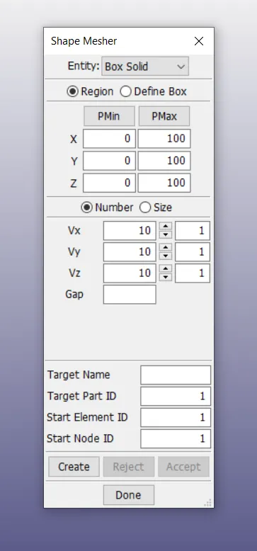
step1: Create the block of dimesions 10mmX10mmX10mm using the shape mesher and input the values as 10 elements in all directions
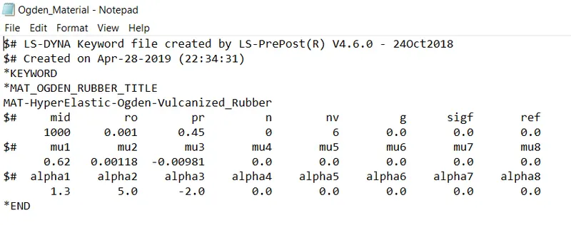
STEP-2: Input the ogden material property into the cube.
step3: Apply the necessary boundary conditions to the block element by allowing the element to move along the x axis with one end fixed.
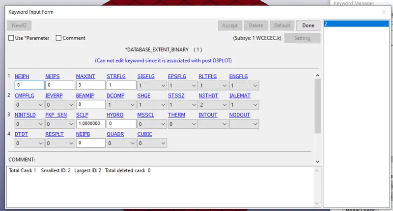
step4: in addition the database extent binary option is added in order to extract the true stress value of the model, by setting the strflg as 1.
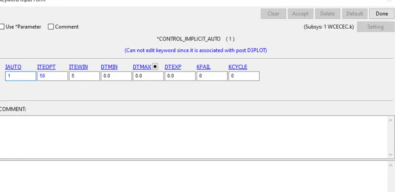
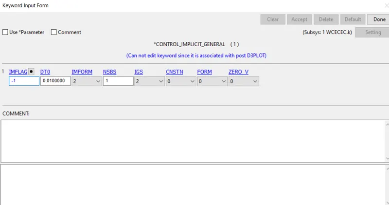
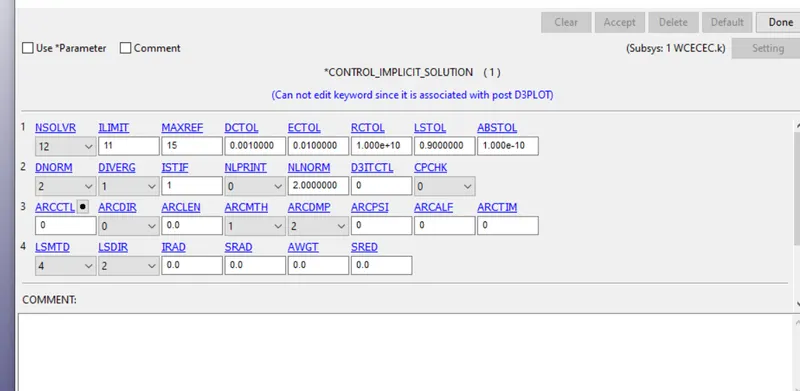
step5: Since this is a non-linear implicit analysis implicit cards like control implicit auto, general and solutions have to be mentioned is addition.
step6: obtain the d3plots after running the analysis in ls program manager.
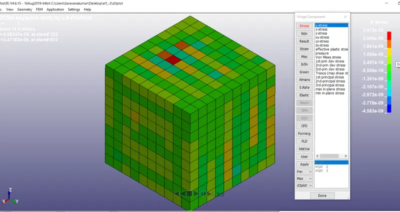
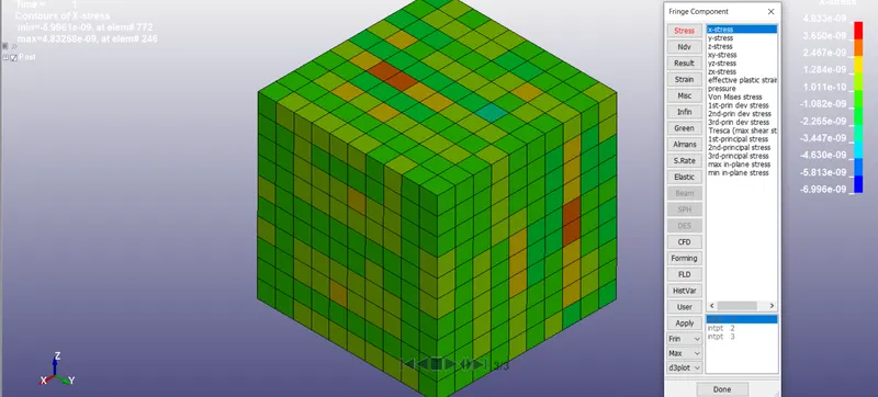
step7: Use various element formulations as recommended and visualize the change in stress of the element using the post processing window, as shown below.
observations for elform in the order of -2,-1,1&2 are shown below.
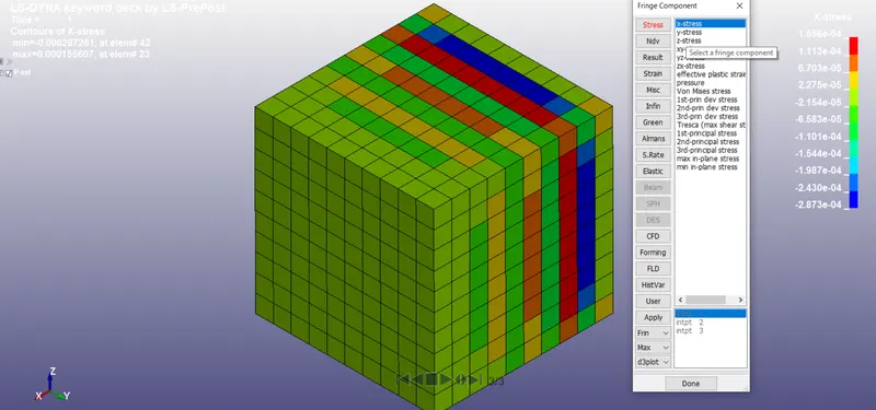
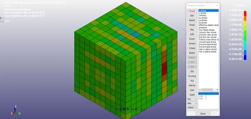
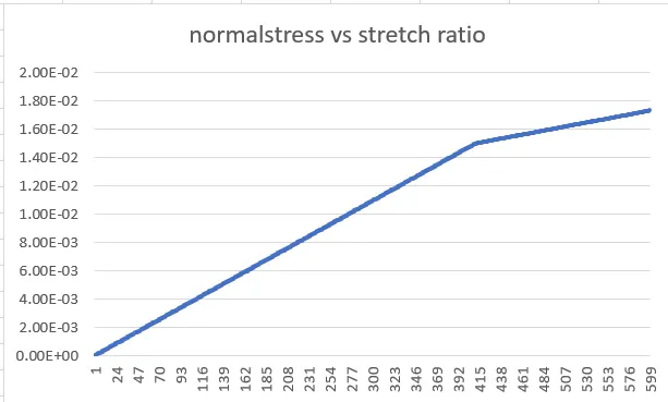
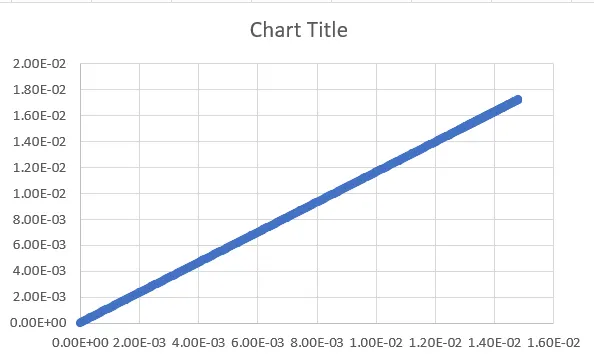
The below graphs shows relation between normal and stretch ratio under tensile loading conditions for various element formulations.
true strain= E= ln(e+1)
true stress= St=Se*(1+e)
Se- engineering stress
e- engineering strain
stretch ratio - Sr=e+1
Normal stress = Ns= St/Sr
elform-2
elform-1
elform1
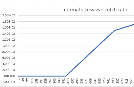
elform2
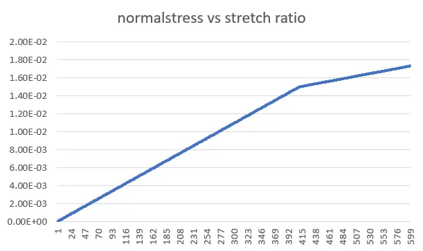
Result:
Thus the graph is sucessfully ploted between the normal stress values and stretch ratio's obtained from the analysed model which was built using various elform's.