Week-6 Calculate the Stretch Ratio by comparing the ELFORM (-2,-1,1,2) with Ogden_Material Model.
OBJECTIVE:
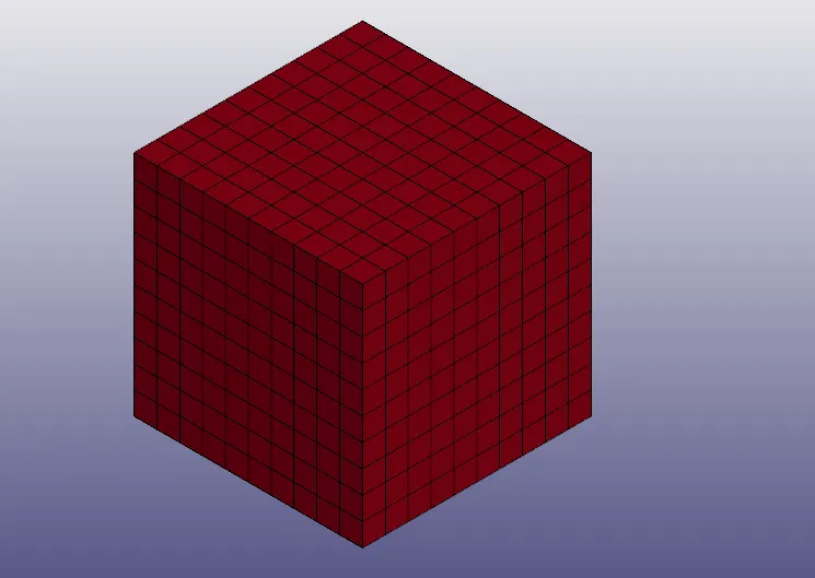
- To create a block of 10mmx10mmx10mm dimension with 10 elements for each direction.
- To assign the given material card to the part.
- Run the model for 4 cases.
- Case 1: ELFORM=1
- Case 2: ELFORM=2
- Case 3: ELFORM=-1
- Case 4: ELFORM=-2
- To calculate for the engineering strain, engineering stress and stretch ratio.
- Compare the results for the simulation using ELFORM = 1, 2, -1, -2
SOLID BLOCK:
BOUNDARY CONDITIONS:
- Simulation time: 5ms
- Nodes are fixed on one side of the solid.
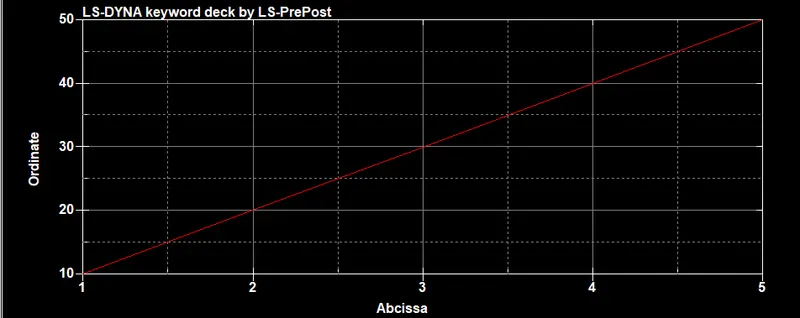
- Displacement is applied in the negative y direction.
DISPLACEMENT CURVE:
SOLVER USED:
Implicit solver is used to run the simulation.
REASONS FOR USING IMPLICIT SOLVER:
- The displacement is linearly increasing with time.
- The rate of expected deformation is less (strain) and so it is a quasi static simulation.
- Less dynamic.
- The material used is hyperelastic (nonlinear material).
RESULTS:
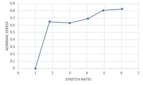
CASE 1: ELFORM=1

NOMINAL STRESS VS STRETCH RATIO:
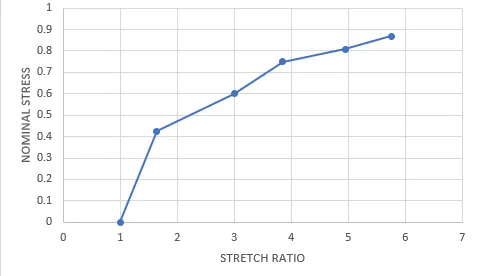
CASE 2: ELFORM=2

NOMINAL STRESS VS STRETCH RATIO:
CASE 3: ELFORM=-1

NOMINAL STRESS VS STRETCH RATIO:
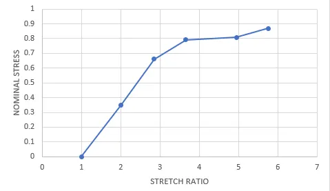
CASE 4: ELFORM=-2

NOMINAL STRESS VS STRETCH RATIO:
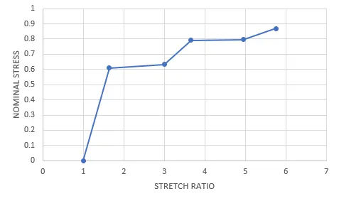
COMPARING THE RESULTS:

NOMINAL STRESS VS STRETCH RATIO:
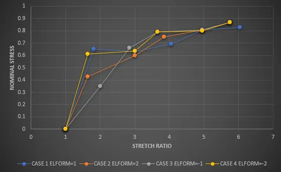
The reults of all the cases are almost similar witha slight difference in stress and strain values.
There are some differences between the actual plot and the obtained plot.
ACTUAL CURVE (NOMINAL STRESS VS STRETCH RATIO):
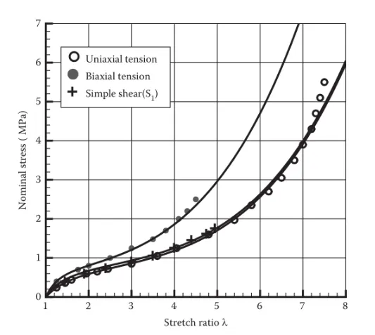
There is a difference of 0.2 to 1.7 when comparing the actual plot and the obtained plot.
This could be because of some variations in the boundary conditions , solid model and mesh generated.
CONCLUSION:
- The tensile test on the hyperelastic material model is completed successfully.
- The engineering stress and the stretch ratio are calculated from the true stress and true strain.
- The nominal stress vs the stretch ratio plot is compared for the four cases.