Week-6 Calculate the Stretch Ratio by comparing the ELFORM (-2,-1,1,2) with Ogden_Material Model.
Objective
- Create a block of 10mmx10mmx10mm dimension with 10 elements for each direction and use the material card attached (Ogden_Material.k) that is representative of the material properties from the above figure.
- Use appropriate boundary conditions to simulate tensile behavior for the model and finally compare the results from your simulation to the plot above up to stretch ratio 5. Only the uniaxial plot is to be compared.
- Compare the results for the simulation using ELFORM = 1, 2, -1, -2
- The unit of µ in the material definition is in MPa and α is a dimensionless quantity. Modify those quantities according to your unit systems.
- Use a proper solver (Implicit/Explicit) and also explain the reason.
Deliverables:
- An excel sheet with proper conversion and calculation of Stress/Strain and the Stretch Ratio for all the ELFORM.
- A proper image of the plot comparison of various ELFORMS against the Uniaxial Plot given in the challenge.
explicit slover
at each node point internal and external forces are summed and accelerating at the nodes is computed F=ma by integrating acceleration in time ,velocity or displacement are calculated and the solution can be advance with respect to time.it is conditionally stable and capable to solve extreme non-linear problem.good for short duration and highly trasient problems.
Implicit solver
a globel stiffness matrix is computed and inverted and applied to the nodal out of balance force to determine the displace ment f=kv. it is unconditional stable and good for long duration.
Ogden material
here we are using the ogden material model to simulate the tensile test.this model is hyperelastic material and used to describe the non-linear stress-strain behaviour of complex materials. such as rubber ,polymers and biological tissue.other hyper elestic material models assumes that the material behaviour can be described by means of a strain energy density function from which the stress-strain relation ships can be derived.
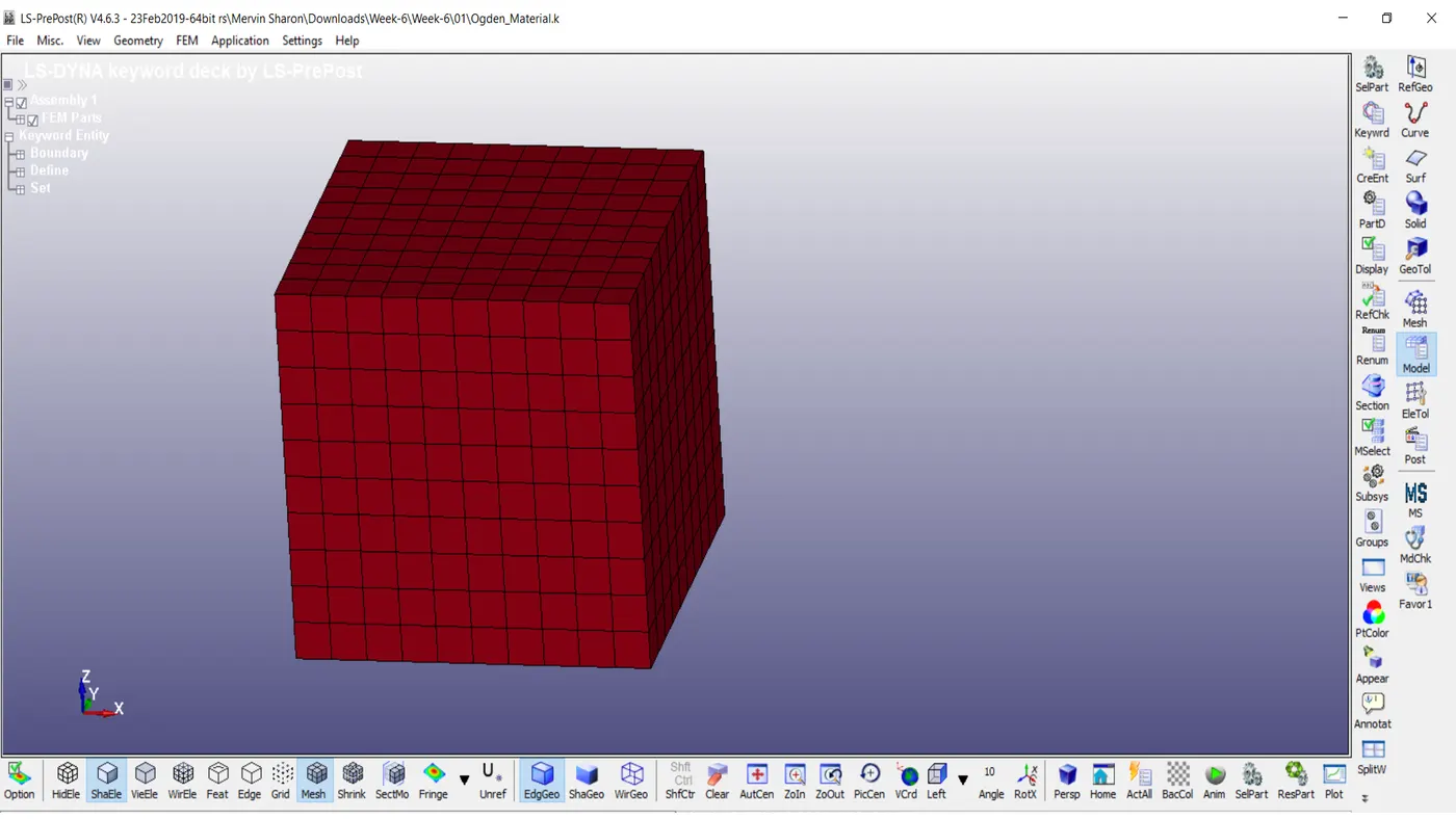
the model a cube 10mm x 10 mm x 10mm here box.solid indicate the hex elements.in the region the cube is given 10mm x,y and z and divided into 10 elements in each direction.
MATERIAL CREATION
a material crad mat_rubber has tobe created and the value have to be taken from the given ogden_material.k.
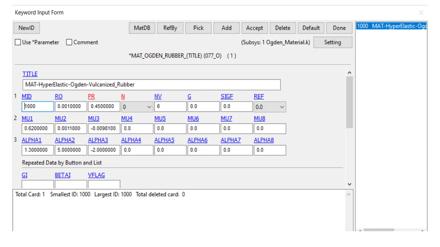
- solid section has to be created with ELFROM (1,-1,2,-2) Start with 1.
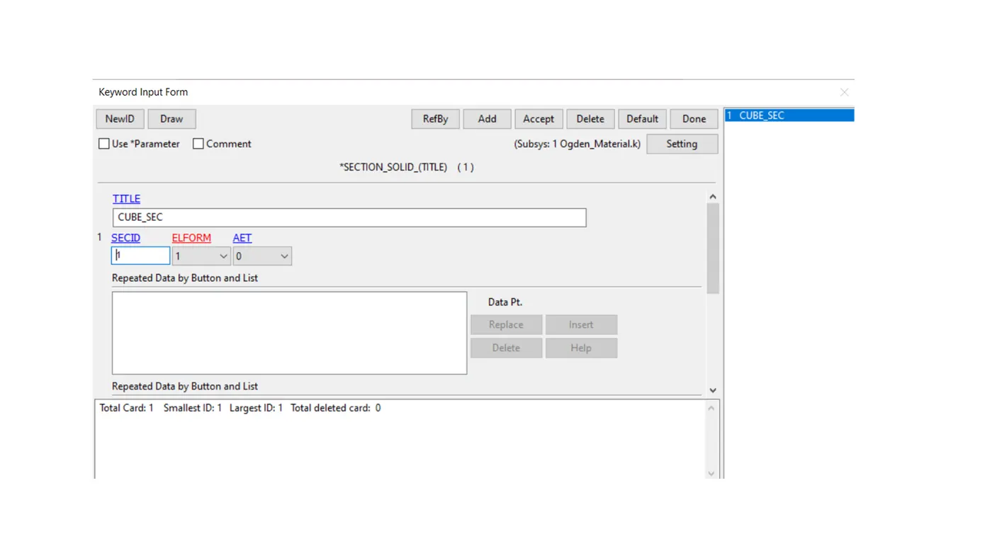
the four different cases that are modeled are modeled using section _soild with 4 different element formulation.
ELFORM 1 - constant stress solid element.
ELFORM 2 - Fully integrated S/R solid.
ELFORM -1 fully integrated s/r solid intented for elements with poor aspect ratio efficient formulation.
ELFORM -2 fully integrated s/r solid intended for elemnts with poor aspect ratio accurate formulation.
BOUNDARY SPC_SET
this keyword is used to constrain a given set of selected nodes on the part along about x,y, and z axis .in our case the nodes present at the left end of the part is constrained in all dofs using keyword.
BOUNDARY _PRESCRIBED _MOTION _SET.
this keyword is used to apply a loading condition to the nodes set of the part model. the required nodes set of the over which the loading is applied can be specified using set_nodes from crent .in our case a prescribed motion is applied in terms of displacement and other parameter as shown below.
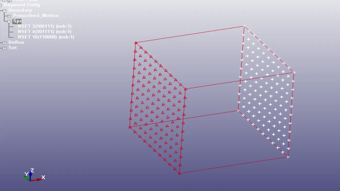
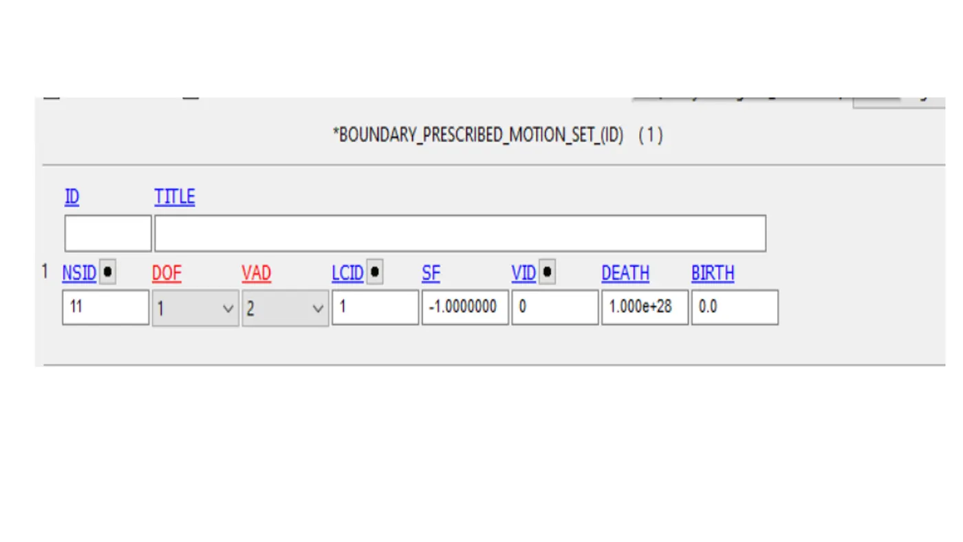
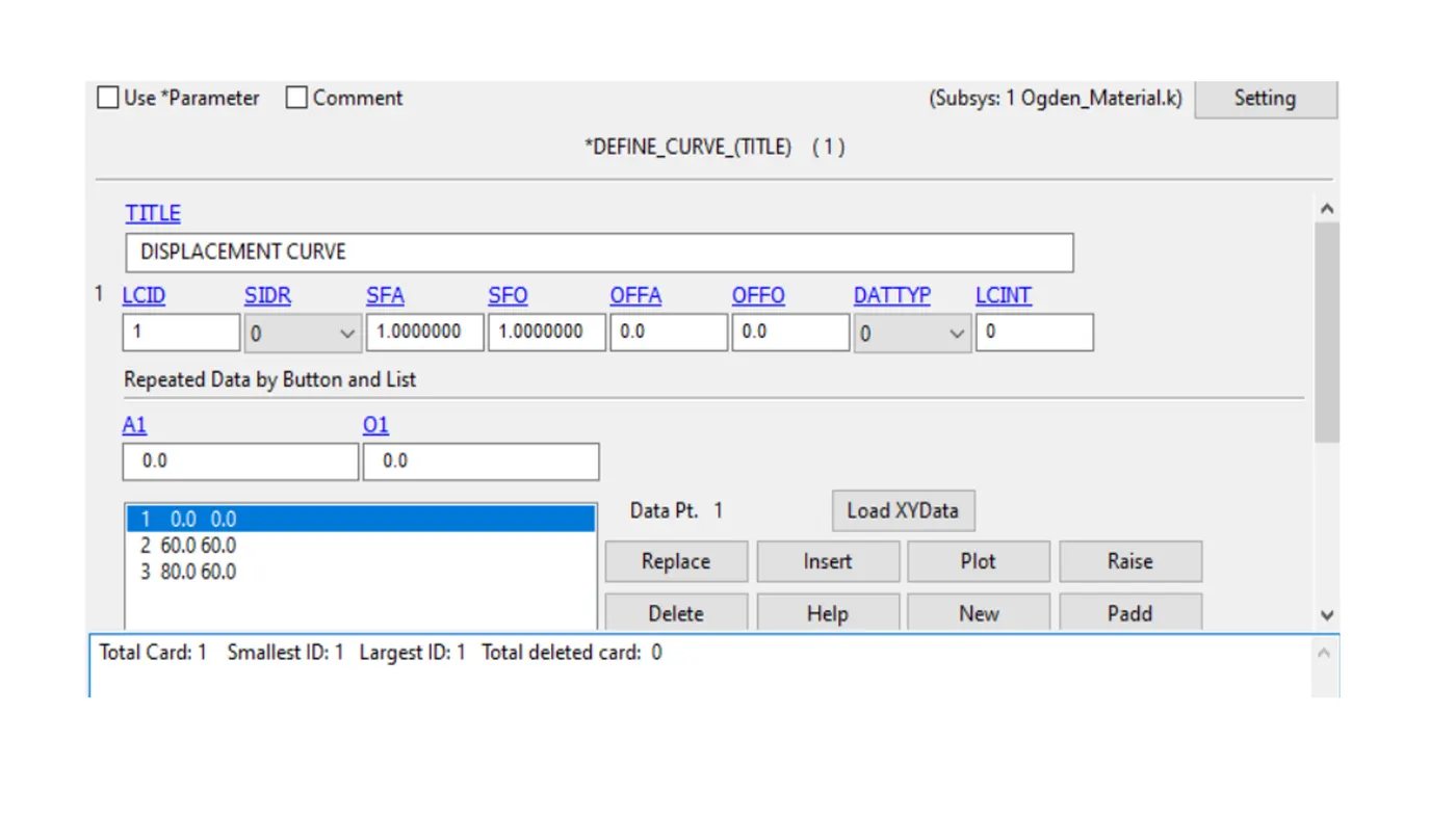
- A prescribed boundary condition has been defined to give a displacement by asssigning a curve is done by using relation .
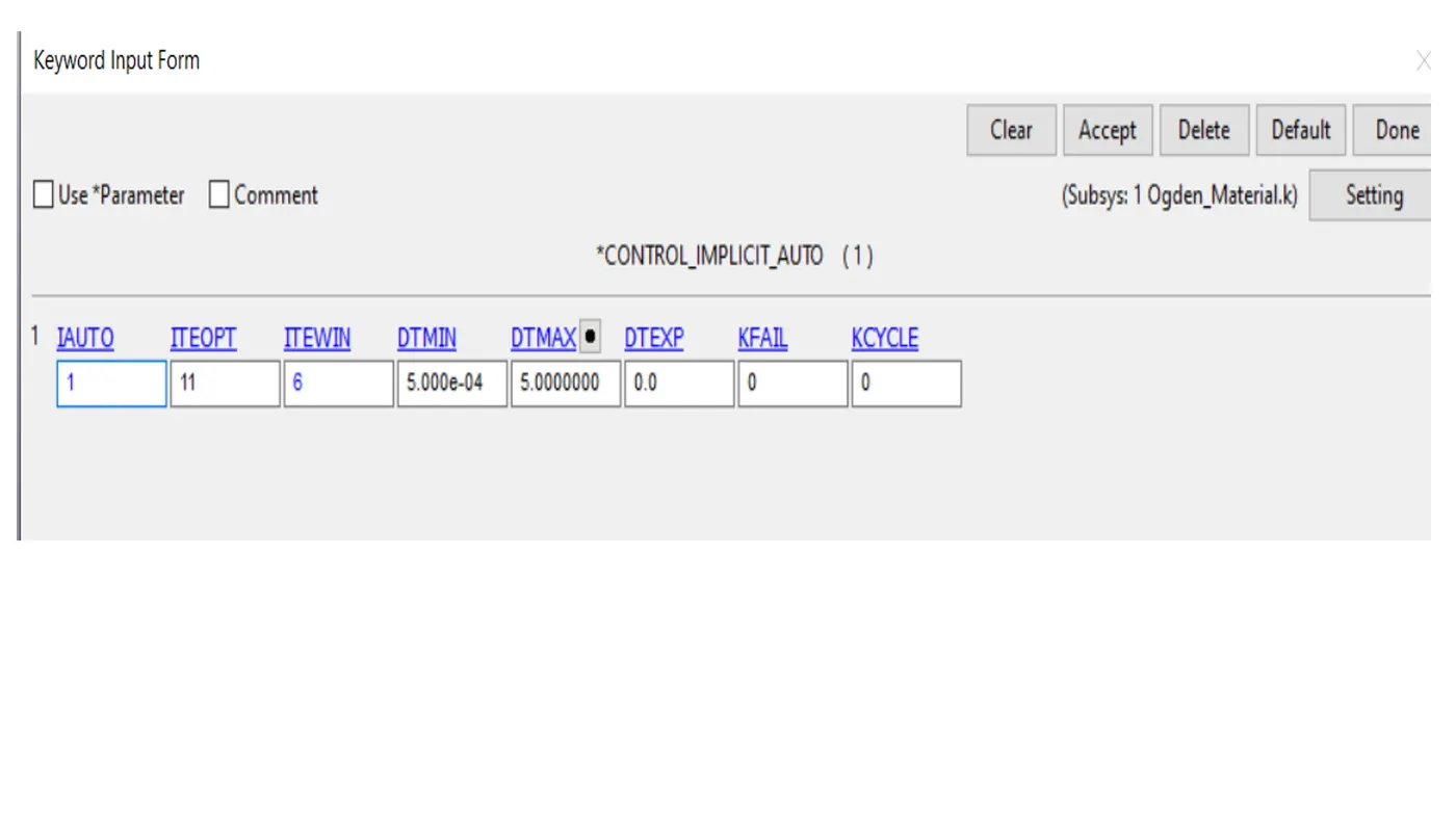
CONTROL_IMPLICIT_AUTO
define parameters for automatic time step control during implicit analysis.
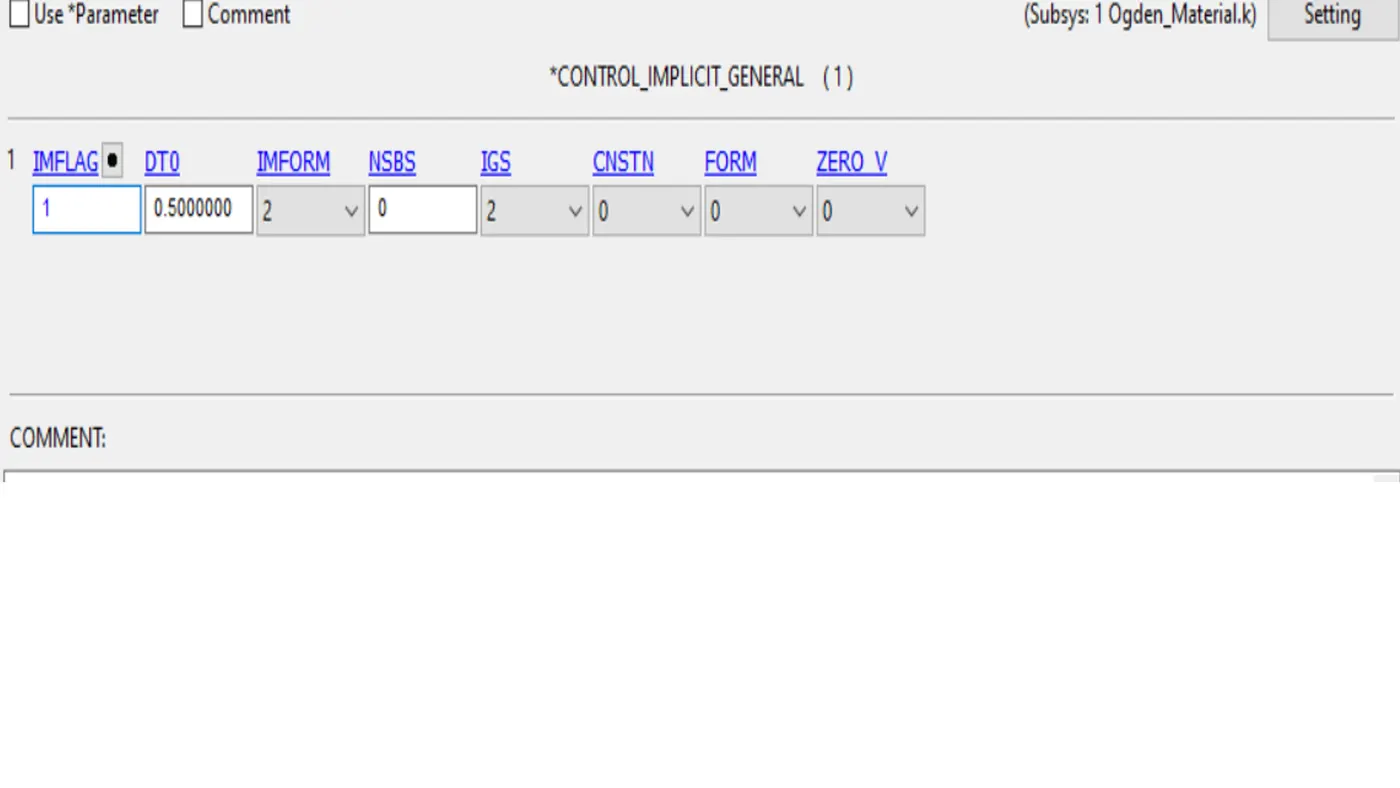
CONTROL_IMPLICIT_GENERAL.
Active implicity analysis and define associated control parameters. the key word is required for all implicit analyses.
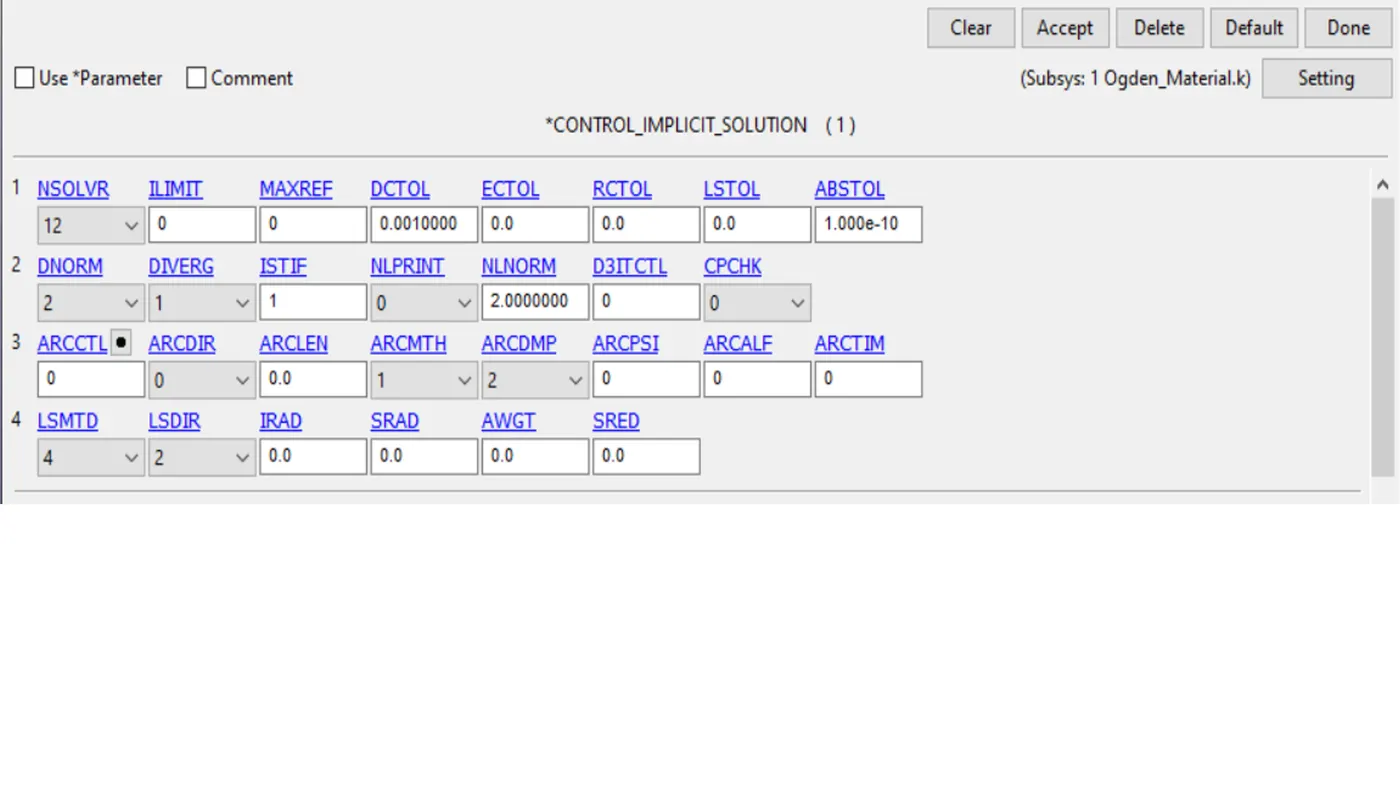
CONTROL IMPLICIT _SOLUTION.
these optional cards apply to implicit calculations use these cards to specify whether a linear or nonlinear solution is desired.
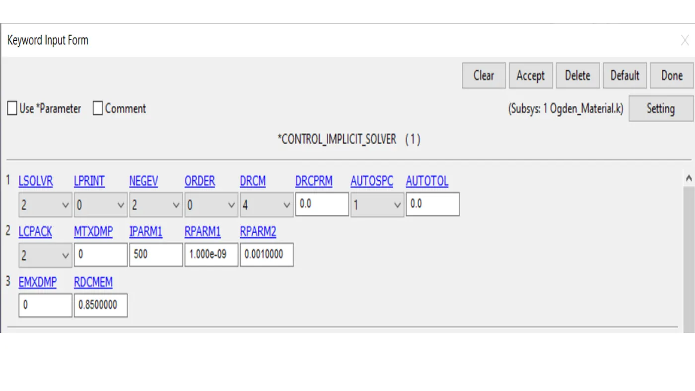
CONTROL_IMPLICIT _SOLVER
these optional cards apply to implicity calculations .the linear equation solver performs the cpu intensive stiffness matrix inversion.
RESULT
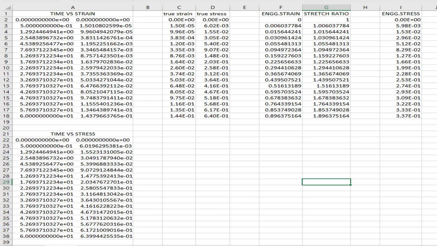
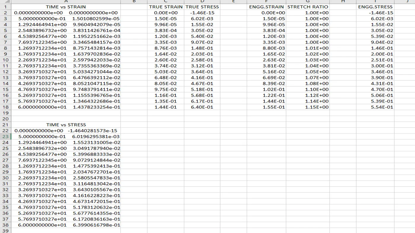
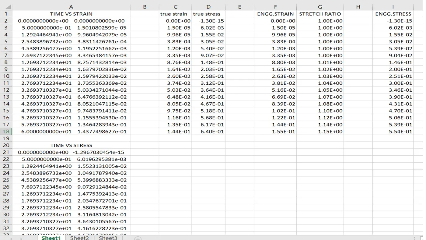
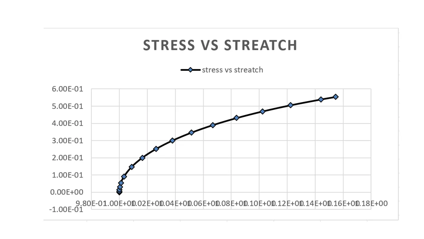
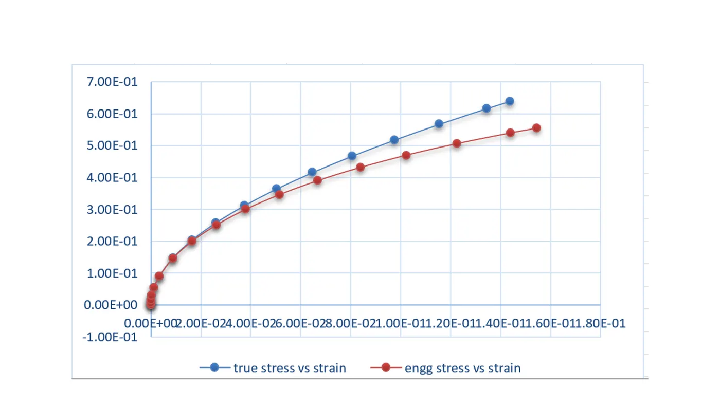
true stress and strain curves have been plotted and saved in.csv format and then graph has to be plotted forengineering stress and stretch .for this it is required to convert true stress and true strain to engineering stress and engineering strain and engineering is converted to stretch using these formulae.
`ɛ_t = ln(1+ɛ_e)=lnλ`. .. 1
to find engineering strain natural log when taken to the other side the engineering strain is the (exponential of true strain-1).
`ɛ_e =Exp(ɛ_t)-1`... 2.
`ɛ_e=Exp(1.33E-02)-1 =1.34E-02` (value taken from data show as an example
to find stretch ,1 is added to engineering strain
`λ=1+ɛ_e....` 3.
`λ=1+ɛ_e = 1+1.34E-02 =1.0134.`
finally enginerring stress is obtained by dividing the true stress with stretch
`σ_t =σ_e * (1+ɛ_e).....(4)`.
`σ_t =σ_e * λ..... (5)` stretch replaces 1+`ɛ_e`from the equation 3.
`σ_e= σ_t /λ`
=1.76E-02/1.0134
=1.74E-02.
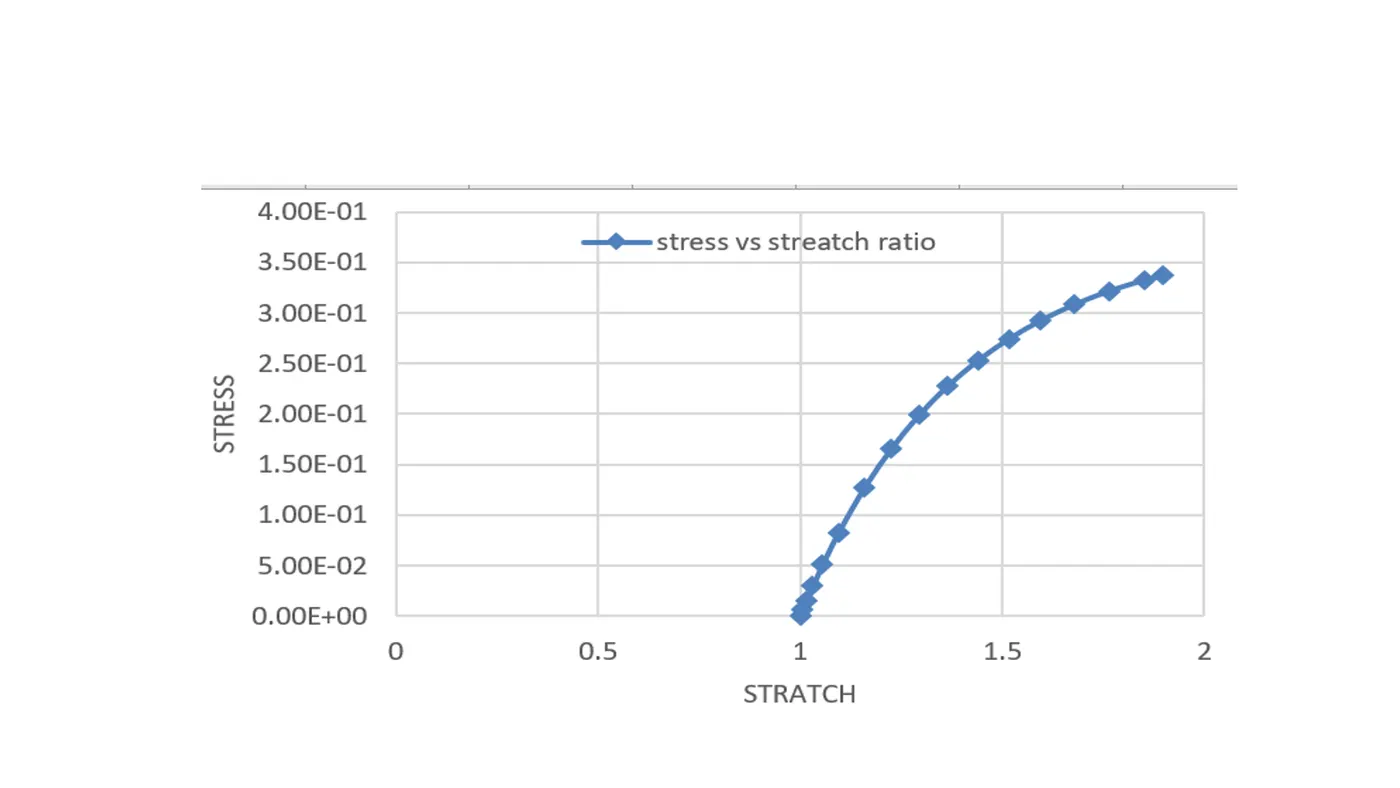
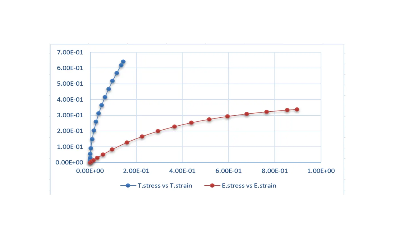
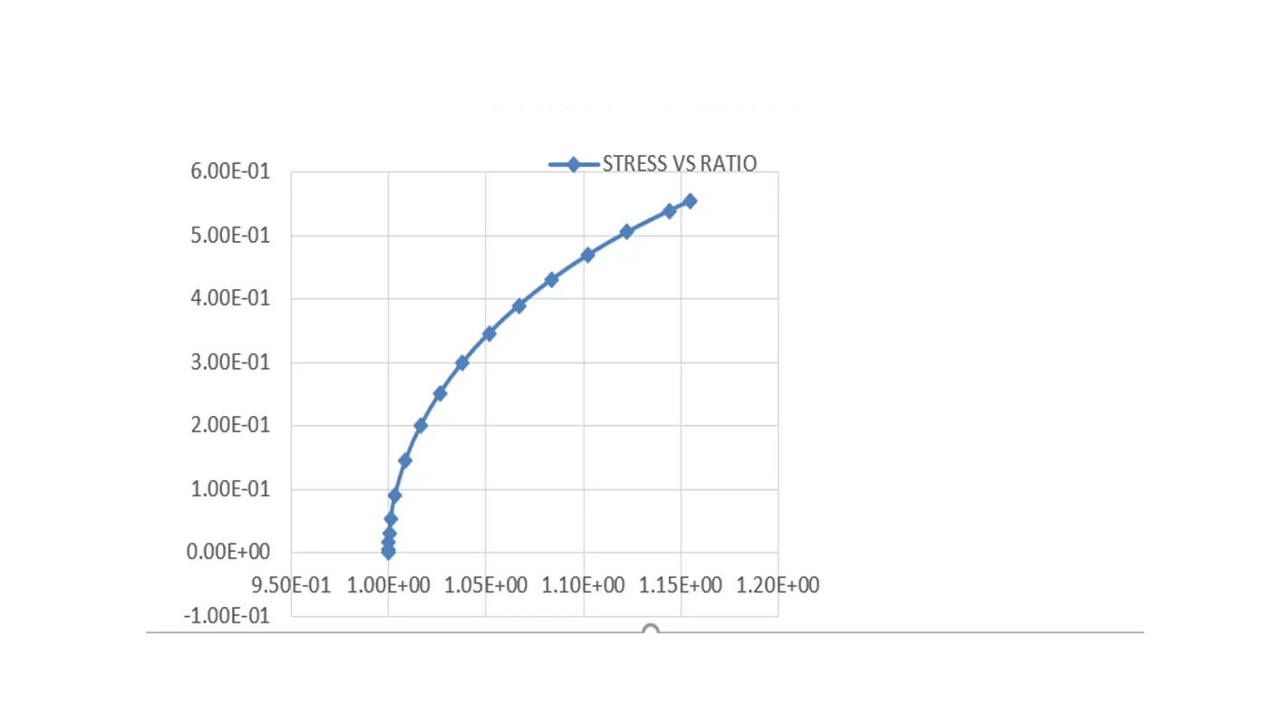
thsis way all the value have been calculated for all the ELFROMS (1,-1,2,-2) and plotted as a graph for engineering stress vs stretch.
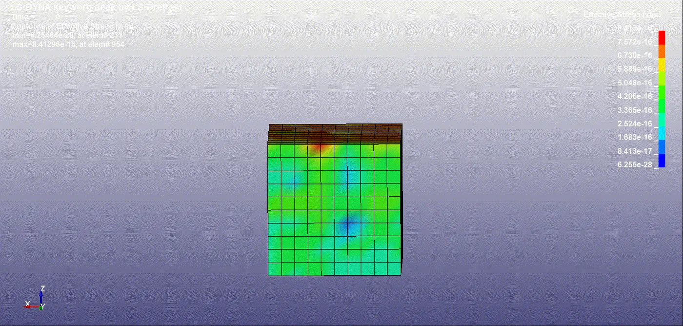
ELFORM :1
ELFORM : -1
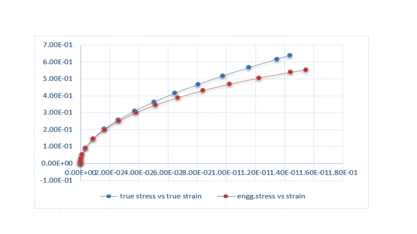
ELFORM :2.
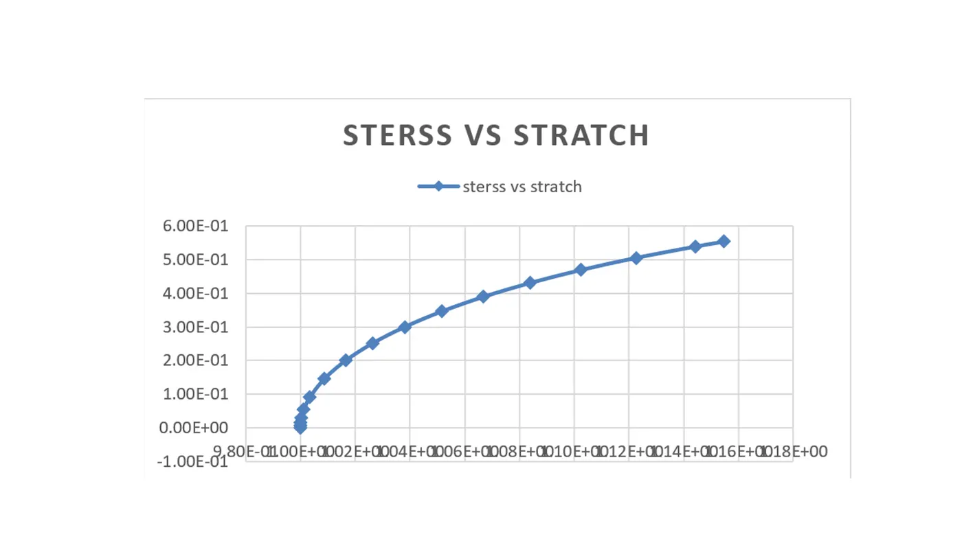
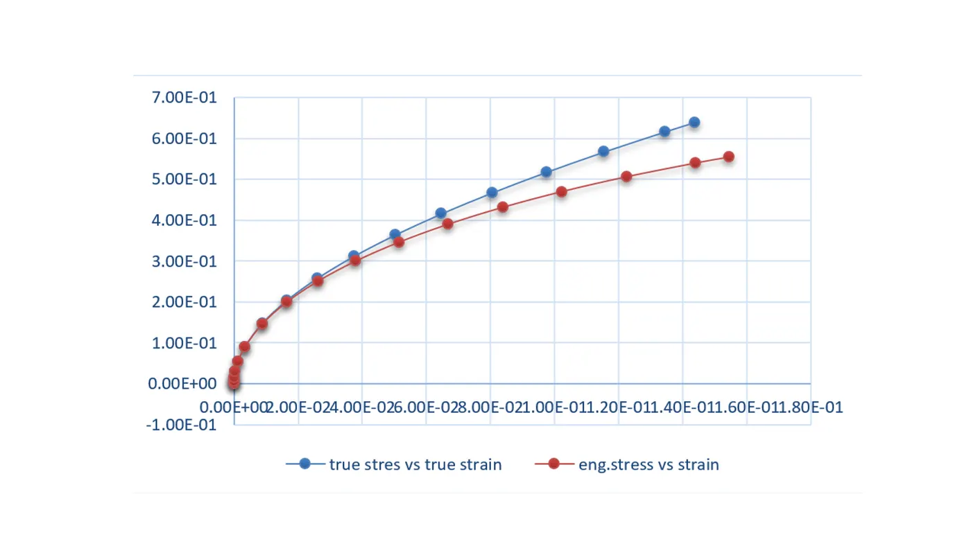
ELFORM : -2
conclusion
in this assignment we learn what is implicit analysis and important key cards and what is true stress and engg stress etc.
the material that is used to model the part also tells us a lot about the deformations that occurred .the MAT_77 is a hyper elastic material we can notice a huge deformation after the yield point while this would not be the case in other materials thart posses high stifness.
all the graphs are in a similar mode but a tensile test with hyperelastic material .ELFORM -1,2,-2 are the most suitable ones and it is even recommended that elform -2 taken when a non linear implicit analysis conducted.