Week-6 Calculate the Stretch Ratio by comparing the ELFORM (-2,-1,1,2) with Ogden_Material Model.
AIM:
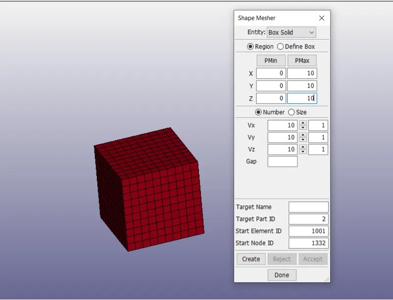
To create a block of 10mm*10mm*10mm dimension with 10 elements each direction and use the material card attached.(ogden_material.k).
To use appropriate boundary conditions to simulate uniaxial tensile behaviour of the model.
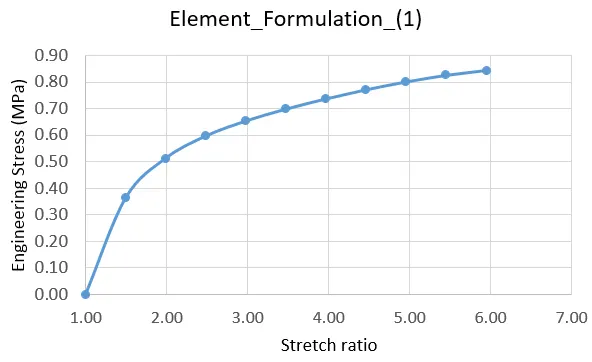
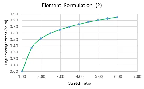
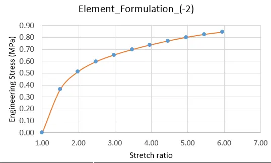
compare the results of the simulation with ELFORM=1,2,-1,-2 by plotting Engineering stress vs stretch ratio up to stretch ratio 5.
To use a proper solver(implicit/explicit).
INTRODUCTION:
In this simulation a solid block is created with appropriate boundary conditions are applied to simulate uniaxial tensile behaviour for the model and stretch ratio is calculated.
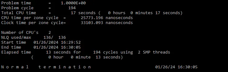
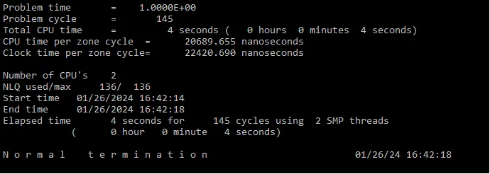
The solver used for this simulation is implicit analysis because the analysis is similar to quasi-static analysis on a hyper elastic non-linear material with slow steady loading condition.
PROCEDURE:
- The given Ls-Dyna keyword file is opened.
- Import the ogden_material_card in the file.
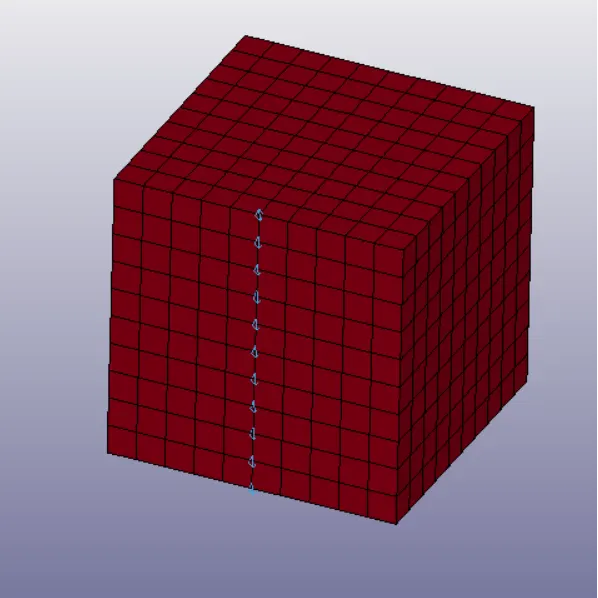
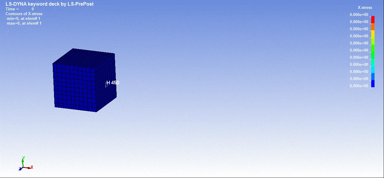
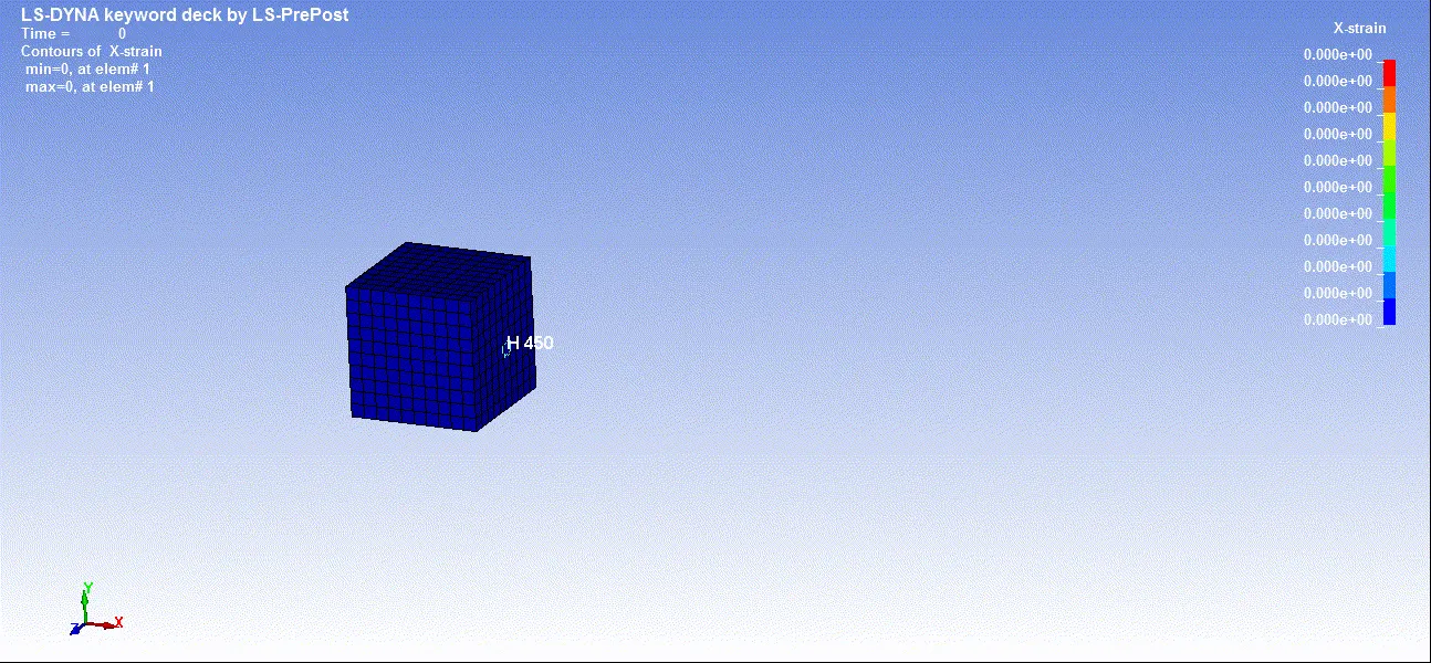
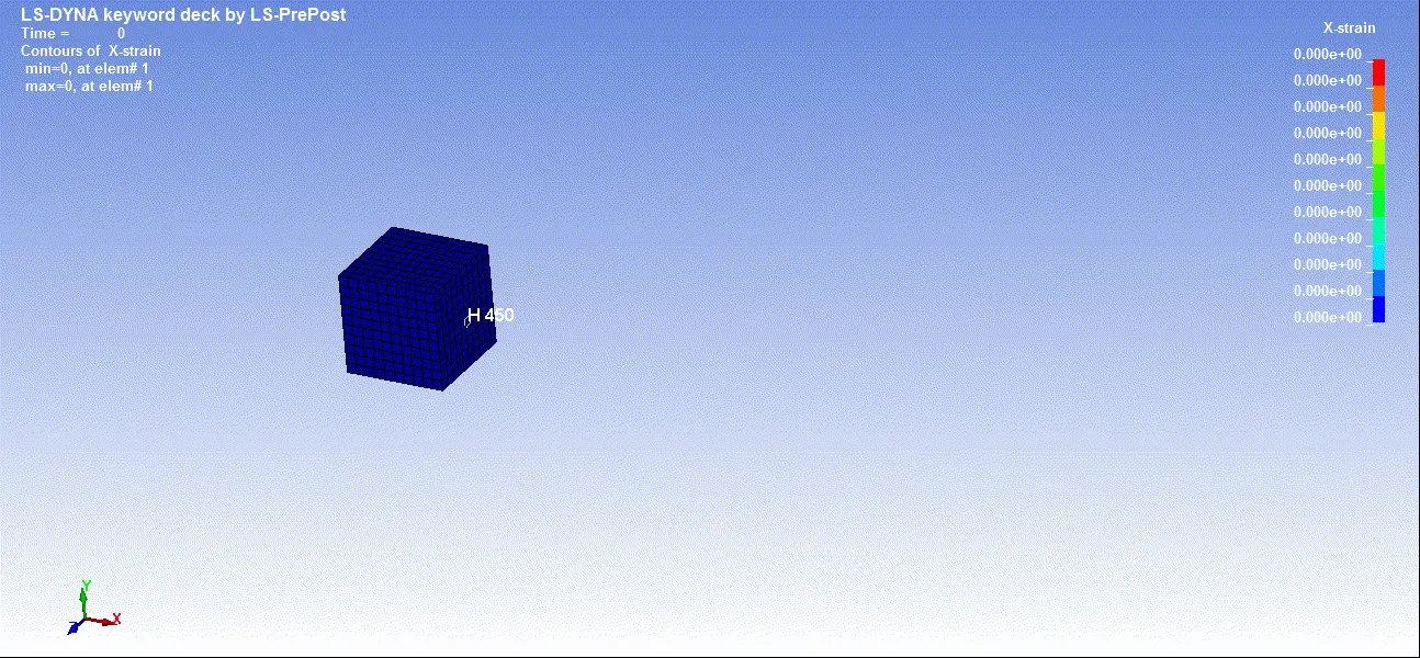
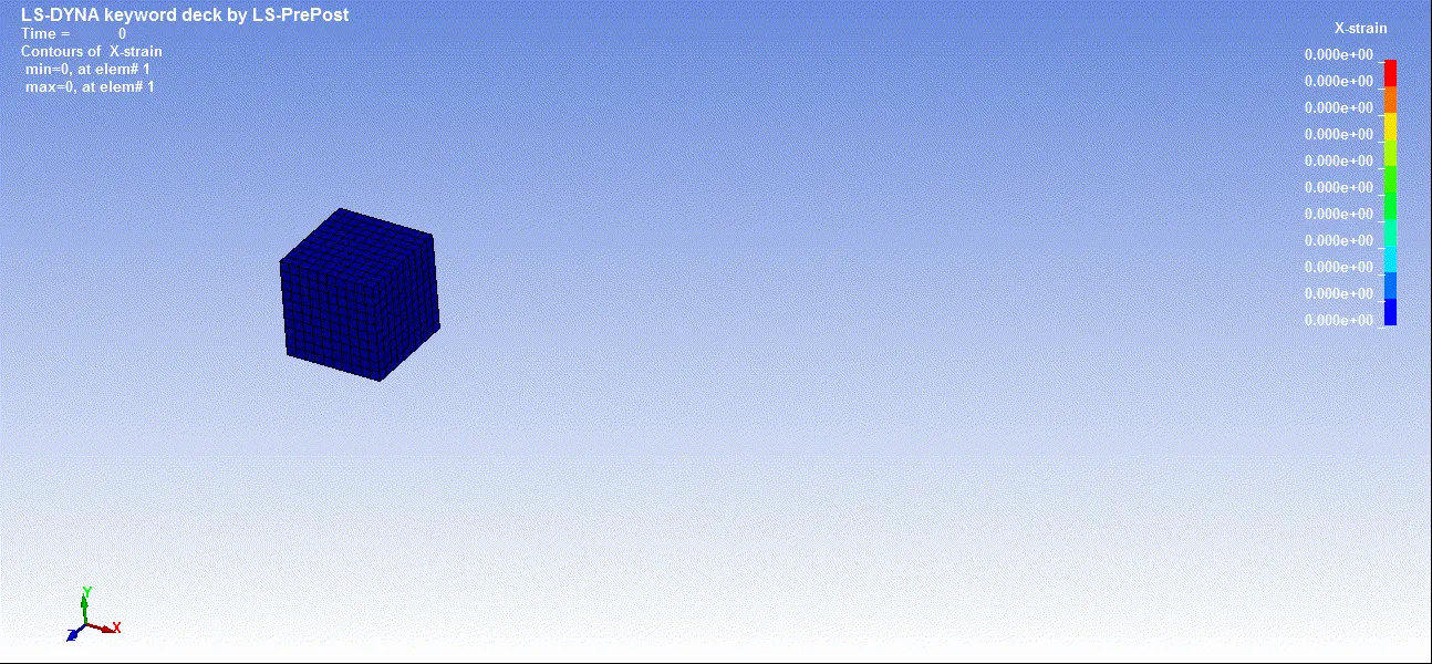
- The FE model of a solid block of 10mm*10mm*10mm dimension with 10 elements for each direction is created as shown below.
PART DEFINITION:
Section properties:
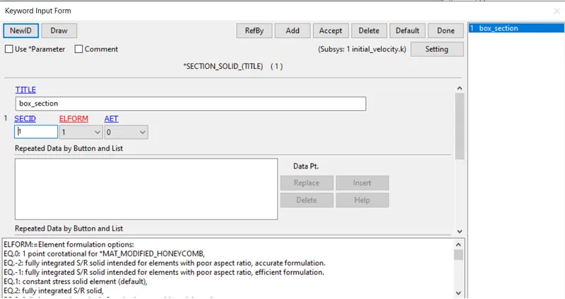
The section properties of the FE model created is assigned as solid elements with different ELFORM such as,
Case(1).ELFORM=1,Constant stress solid elements.
Case(2).ELFORM=-1,Fully integrated S/R solid intended for elements with poor aspect ratio, efficient formulation.
Case(3).ELFORM=2,Fully integrated S/R solid.
Case(4).ELFORM=-2,Fully integrated S/R solid intended for elements with poor aspect ratio, accurate formulation.
Note: The simulation has to be executed for each case separately.
Material properties:
Keyword manager>mat>077_OGDEN_RUBBER
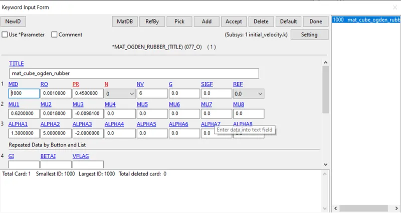 The above material card is already provided as a keyword file and it is assigned to the solid block part.
NOTE: The unit of μ in the material defination is in MPa and α is a dimension less quantity.
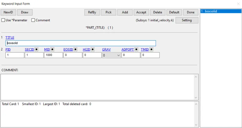
Part definition:
BOUNDARY CONDITIONS:
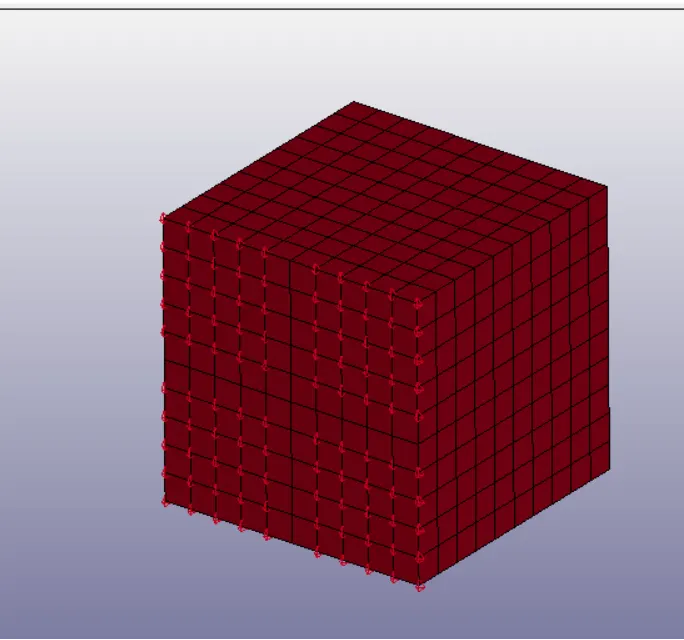
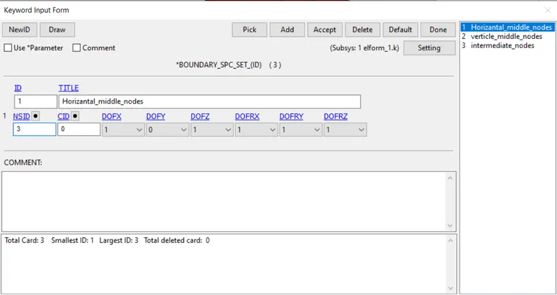
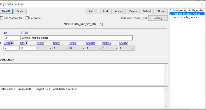
To perform uniaxial tensile test on the specimen, the nodes of one of the faces is fixed as shown in the following figure.
The minimum load to be applied in x-direction on the moving surface to attain a stretch ratio 5,is calculated by using following relations.
we know that Engineering strain means change in length divided by original length.
εe=δl/l
stretch ratio
λ=1+εe
5=1+δl/10
δl=40mm,
Hence, minimum value of 50mm is taken to define the load curve.
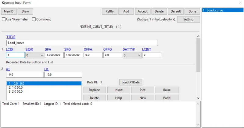
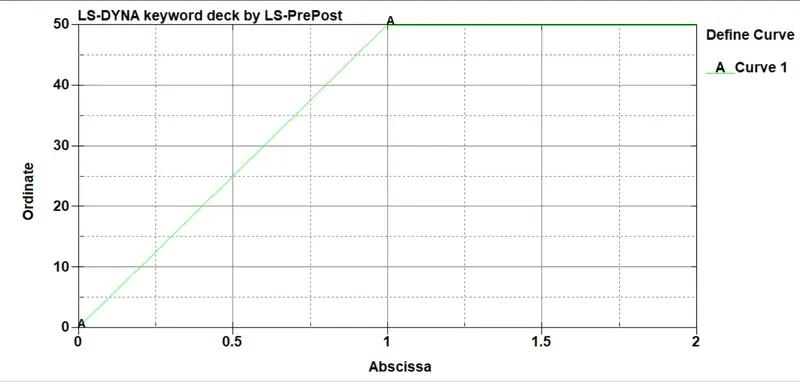
BOUNDARY_PRESCRIBED_MOTION_SET Card is used to apply the boundary condition on the moving surface. To perform the uniaxial tensile test on the specimen.
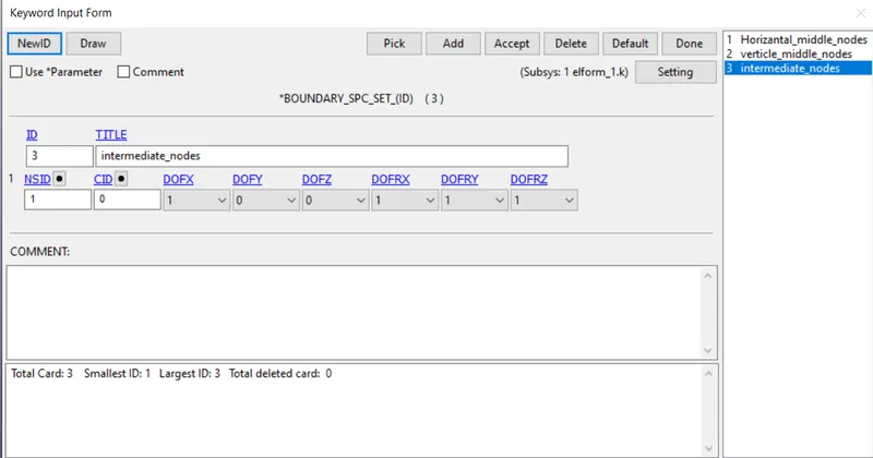
The nodes of one of the faces are fixed along x-axis
CONTROL FUNCTION:
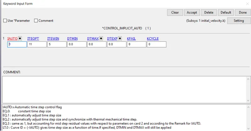
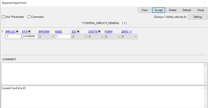
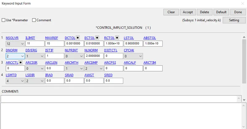
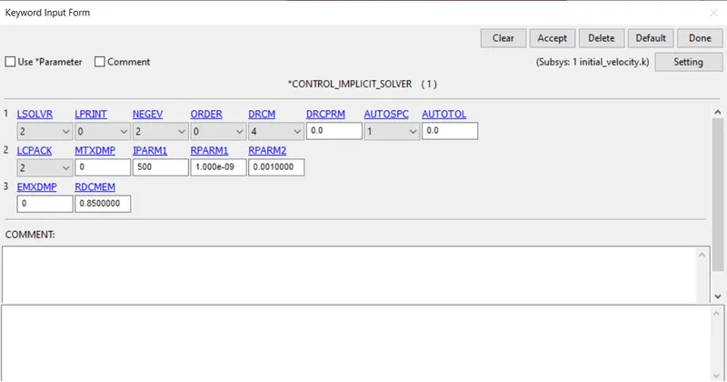
CONTROL_IMPLICIT_SOLVER is used for implicit calculation.
DATABASE:
- BINARY_D3PLOT
- EXTENT_BINARY
- ASCII(ELEOUT,NODOUT,MATSUM,GLSTAT)
RESULT:
- From the above simulation we will get true stress and true strain graph as a result.
- with the resultant data we will have calculated engineering stress and engineering strain by formula.
ELFORM1
It is a constant stress solid element(default),it has hourglass control for large deformation.it is accurate and has low computational cost than others.
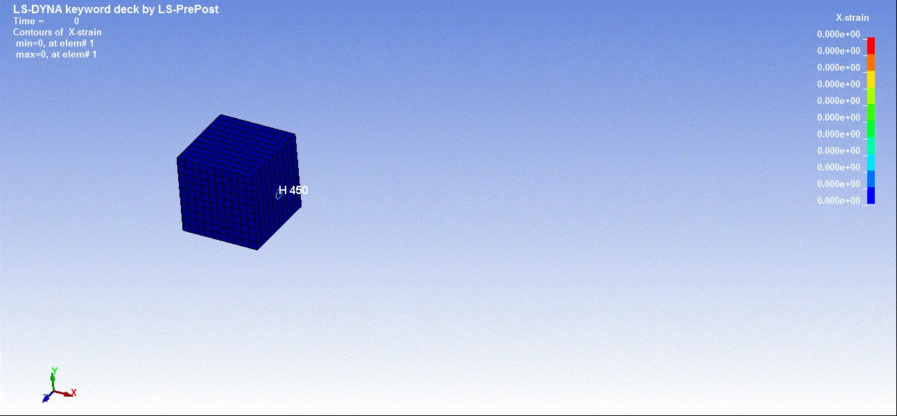
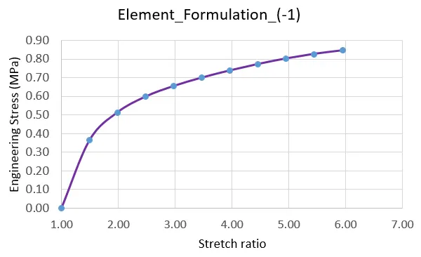
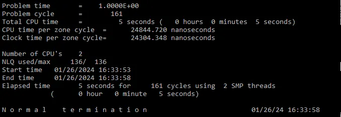
ELFORM-1
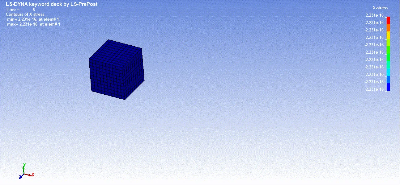
Fully integrated solid intended solid for elements with poor aspect ratio with efficient formulation.
ELFORM2
Fully integrated solid elements with reduced stiffness matrix.
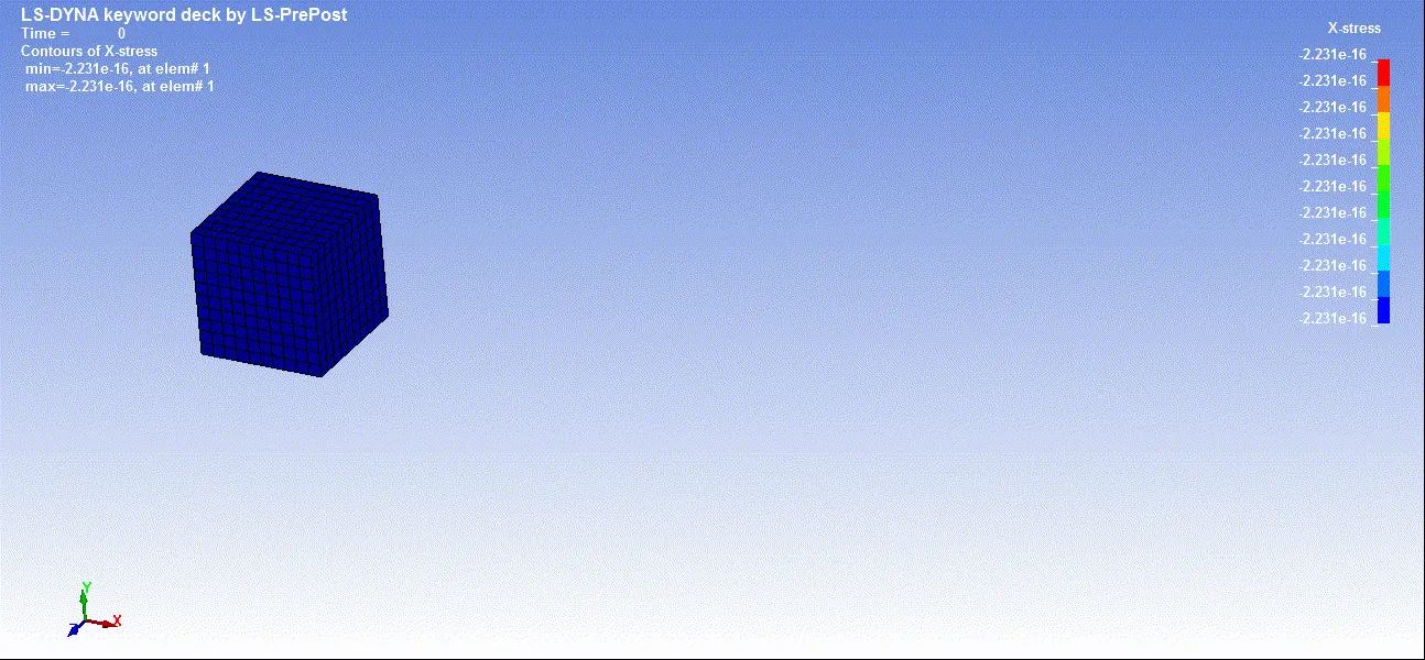
ELFORM-2
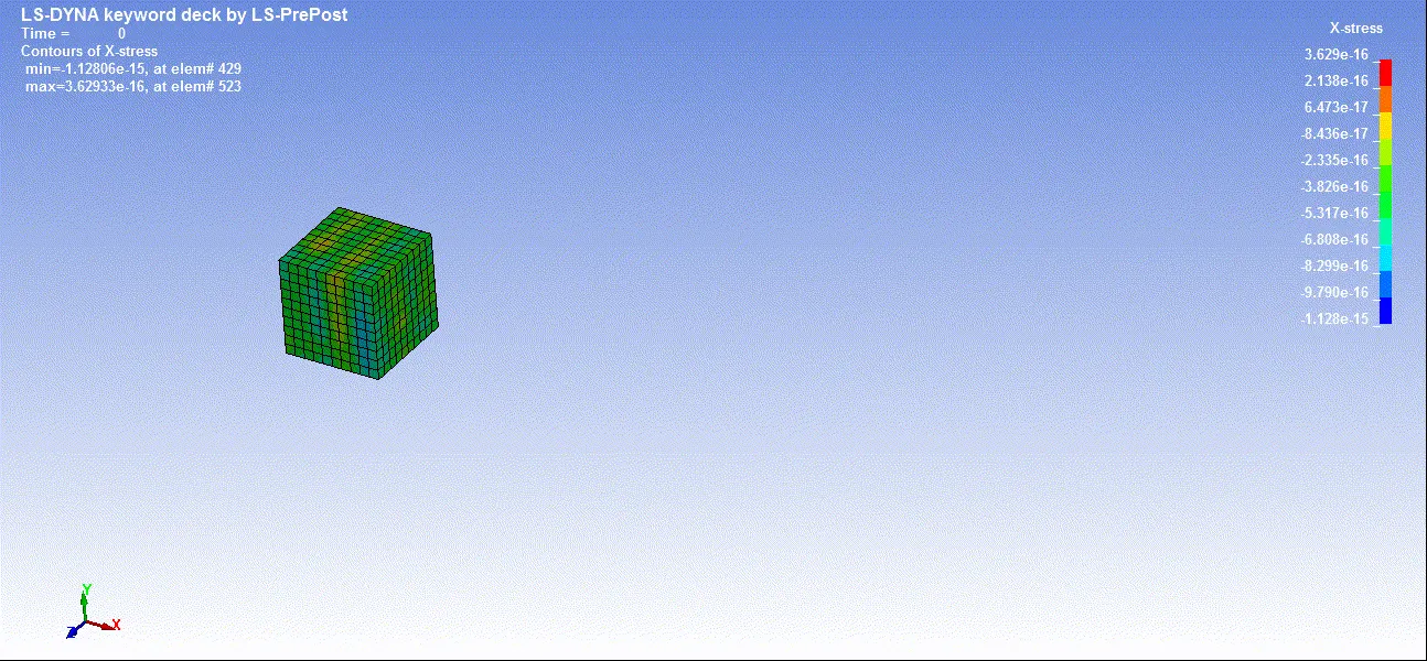
Fully integrated solid intended solid for elements with poor aspect ratio with accurate formulation.
Conclusion:
Comparing the plot of Stress vs Stretch ratio for various element formulation, there is no significant difference in either the number of load steps required for convergence or variation in the results.
Elform 1 : Constant stress solid element.
It is efficient and accurate. Works well with severe deformation but needs hourglass stabilization.
Elform 2: 8 point hexahedron
It is slower than Elform 1, becomes stiff in case of poor aspect ratio, may result in shear locking and unstable in large deformation but doesn’t need hourglass stabilization.
Elform -1: 8 point hexahedron intended for elements with poor aspect ratios
It is identical with type 2, but accounted for poor aspect ratio in order to reduce shear locking.
Elform -2: 8 point hexahedron intended for elements with poor aspect ratios
It is identical with type 2, but accounted for poor aspect ratio in order to reduce shear locking but with higher computational cost than elform -1.
Though there is change in the way of calculation for different element formulation, the stress and strain values in the above plots are identical because of the simple model with elements having good aspect ratio that is there is no much variation in the values and taken for convergence are comparable
Google Drive Link for Excel file, K file & d3plot file:
https://drive.google.com/file/d/1DpRAj1WKO28vBsi5oO_kaxEZWdNLqJMm/view?usp=drive_link