Week-6 Calculate the Stretch Ratio by comparing the ELFORM (-2,-1,1,2) with Ogden_Material Model.
STRETCH RATIO COMPARISON FOR SOLID ELFORM(-2,-1,2,1) WITH OGDEN MATERIAL
OBJECTIVES :
To compare the different solid element formulations for a cube of 10mmx10mmx10mm dimension for Stretch ratio and Engineering stress.
EQ.-2: Fully integrated S/R solid intended for elements with poor aspect ratio, accurate formulation.
EQ.-1: Fully integrated S/R solid intended for elements with poor aspect ratio, efficient formulation .
EQ. 1:Constant stress solid element: default element type. By specifying hourglass type 10 with this element, a Cosserat Point Element is invoked and needs hourglass control.
EQ. 2: Fully integrated S/R solid but susceptible to shear locking.
PROCEDURE :
1. Open the 'ogden_material.k' file in LS prepost.
2. Create a cube of 10x10x10mm with element size 1mm using Mesh module > Shaper Mesher.
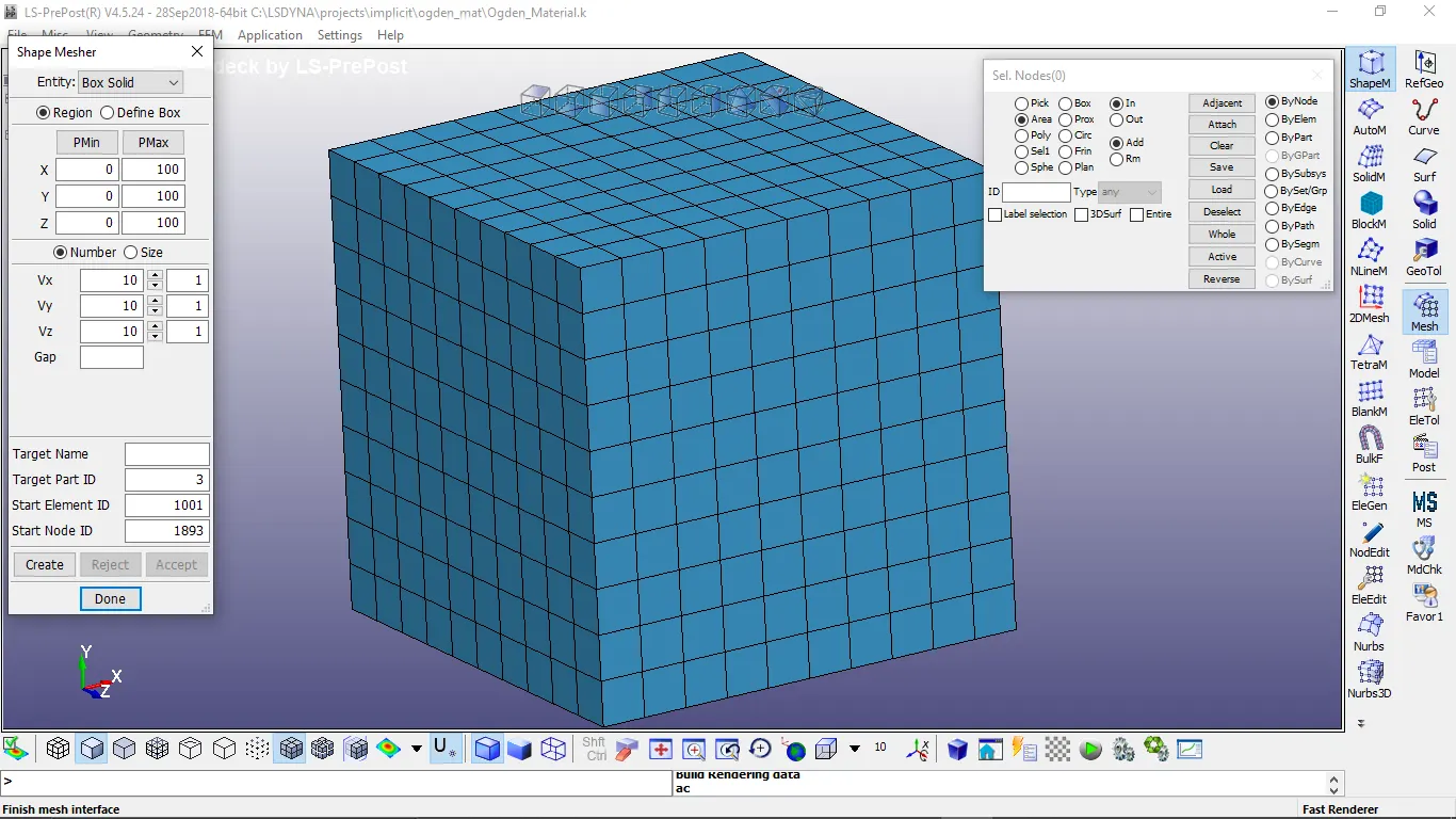
3. Create a section keyword for solid with ELFORM=1 under Model module > Keyword.
4. Create a node set to constraint the cube with three boundary conditions.
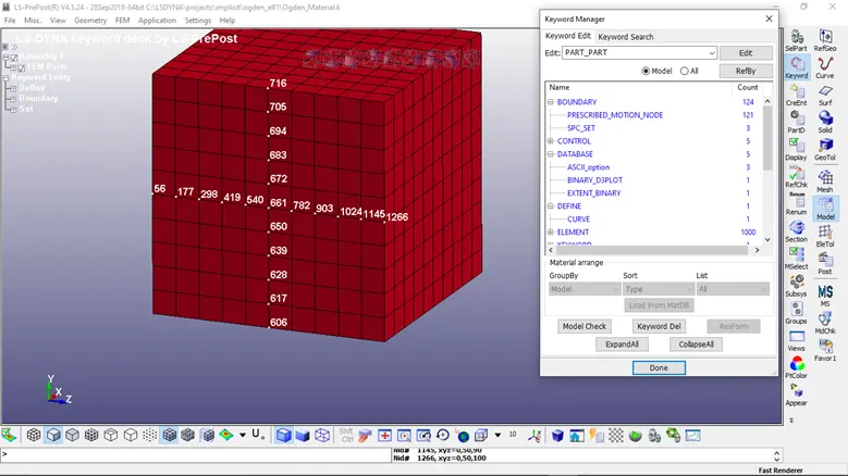
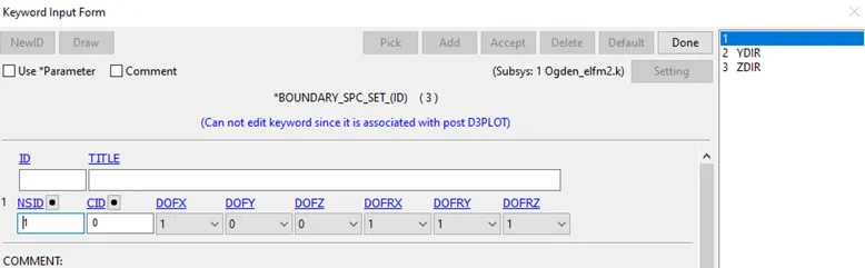
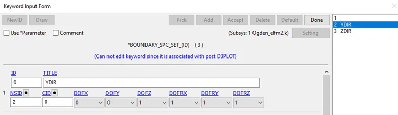
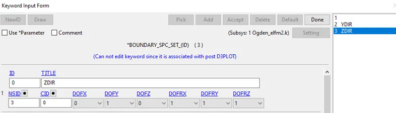
In the boundary condition ID 1, the elements on the left side are constrained in X,RX,RY,RZ DOFs since for the tensile test for the component is pulled in the positive X direction on right side while the left side remains fixed. In the boundary condition 1D 2, the middle nodes along direction Y is constrained in Z,RX,RY,RZ DOFs. In the boundary condition 1D 3, the middle nodes along direction z is constrained in Z,RX,RY,RZ DOFs. Due to necking of the component, the boundary conditions act in aid of the specimen.
5. Create a Boundary > prescribed_motion_set and select all the nodes and assign the displacement curve for 60mm along x axis.
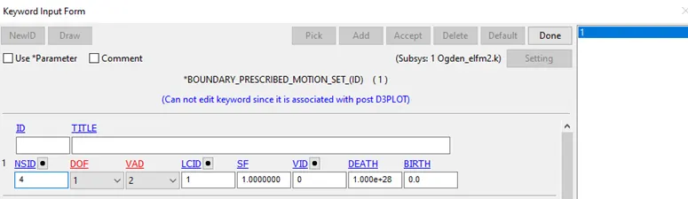
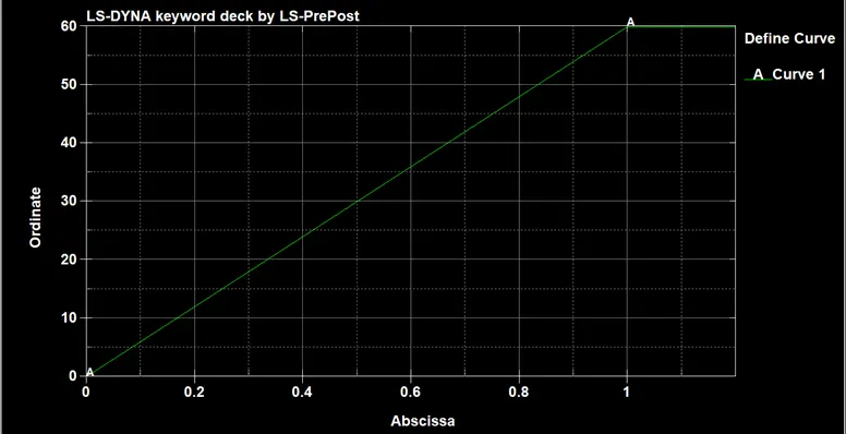
The Tensile load is applied by displacement vs time plot. At the enf of 1ms, the displacement on one side of the cube would be 60mm.
The required stretch ratio λ is 5.
Using relation between true strain and true stress, ɛt = ln(1+ɛe) = lnλ, where ɛe is true strain, ɛt is true stress and λ is stretch ratio.
wkt, 1+ ɛe = λ => ɛe = 4
also, ɛe = Δl/l => Δl = 4 x 10 = 40mm , which is minimum displacement needed to achieve a stretch ratio of 5.
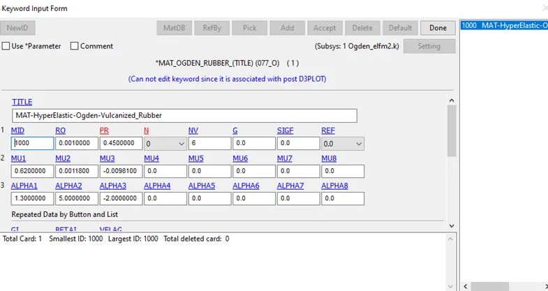
6. The Ogden material card, which is hyperelastic material and solid section is assigned to the part keyword.
7. Now assign control cards for Implicit simulation, so we can get accurate results for simple non-linear analysis. This method inverses stiffness matrix at static equilibrium problems like simple tensile tests. For linear problems timesteps can be higher and it is called unconditionally stable analysis. While Explicit analysis is carried out for non-linear dynamic problems where inertial forces are important like in a car crash.
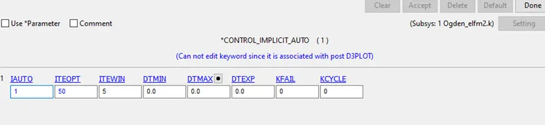
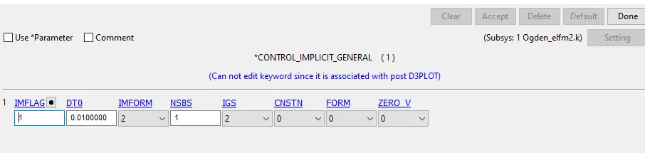
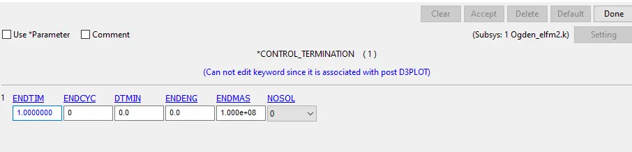
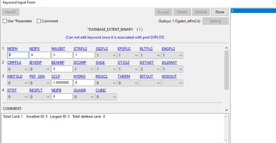
8. Assign Database > ASCII, Binary_d3plot and in Extend binary set STRFLG=1. This gives strain rate data.
9. Check the model and run simulation in LS-Dyna Manager.
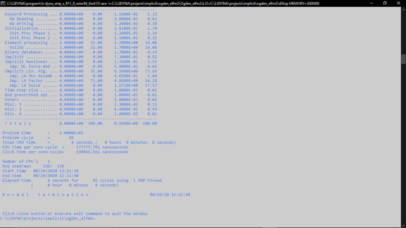
10. Open Binary d3plot file in LSprepost and run the simulation.

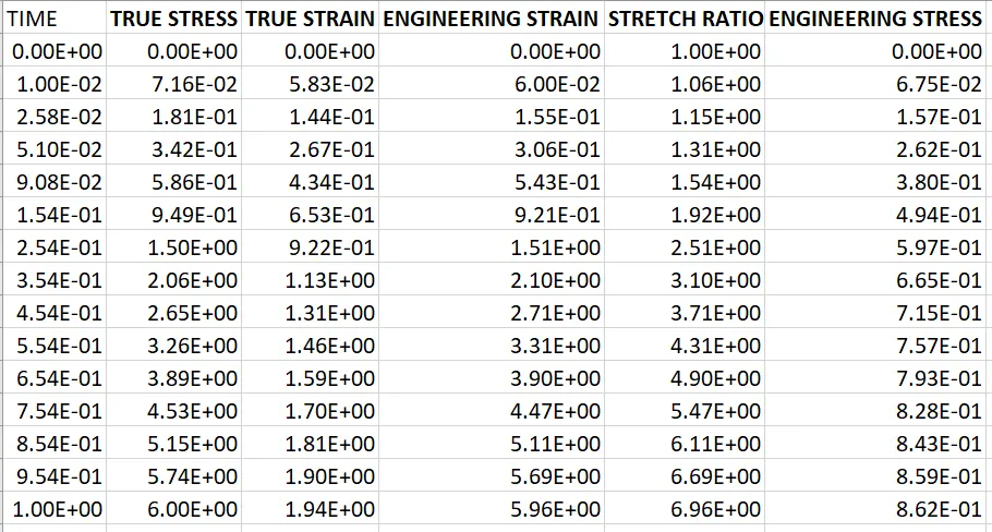
11. The true stress(MPa) and true strain(no unit) values are saved from xstress and lower ipt xstrain History plot for element 955 middle of the component.
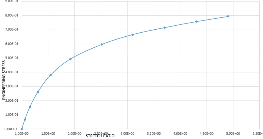
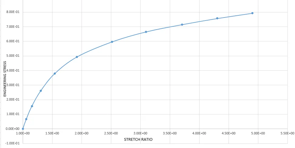
ELFORM =1 , In the graph the stretch ratio upto 5 is plotted for all solid element formulations.
Using relation, ɛt = ln(1+ɛe) = lnλ
we get, e(ɛt) - 1 = ɛe , where ɛe is Engineering strain, ɛt is true strain and e is exponetial.
also, λ = 1+ ɛe , where λ is stretch ratio.
we know that, σt = σe * (1+ɛe) => σt = σe * λ => σe = σt/λ ,where σe is Engineering stress, σt = Engineering strain.
Example :
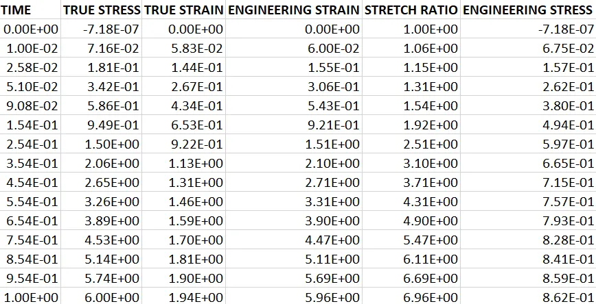
Take, true stress(σt) = 1.81E-01 , true strain(ɛt) = 1.44E-01
e(ɛt) - 1 = ɛe => e(1.44E-01) - 1 => ɛe = 1.55E-01
λ = 1+ ɛe => 1 + 1.55E-01 => λ = 1.15
σe = σt/λ => 1.81E-01 / 1.15 => σe =1.57E-01
Similary, all the Engineering stress(MPa), Stretch ratio and Engineering strain values are calculated and presented in Excel Workbook.
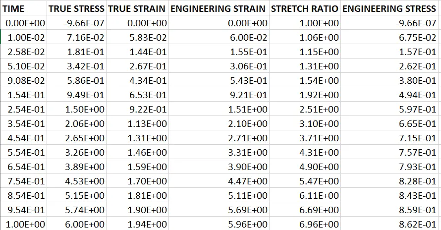
12. The ogden_elf1.k is saved to another folder and renamed for respective element forms and the Solid section ELFORM is changed to -1,2,-2 simultaneously using notepad++.
ELFORM = -1
ELFORM 2
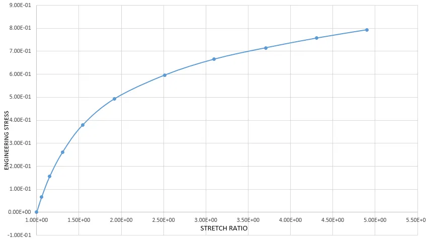
ELFORM -2
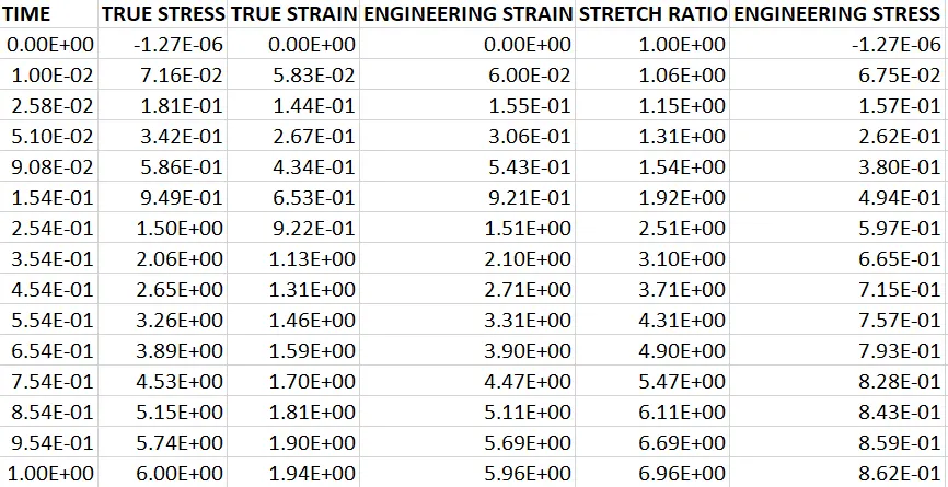
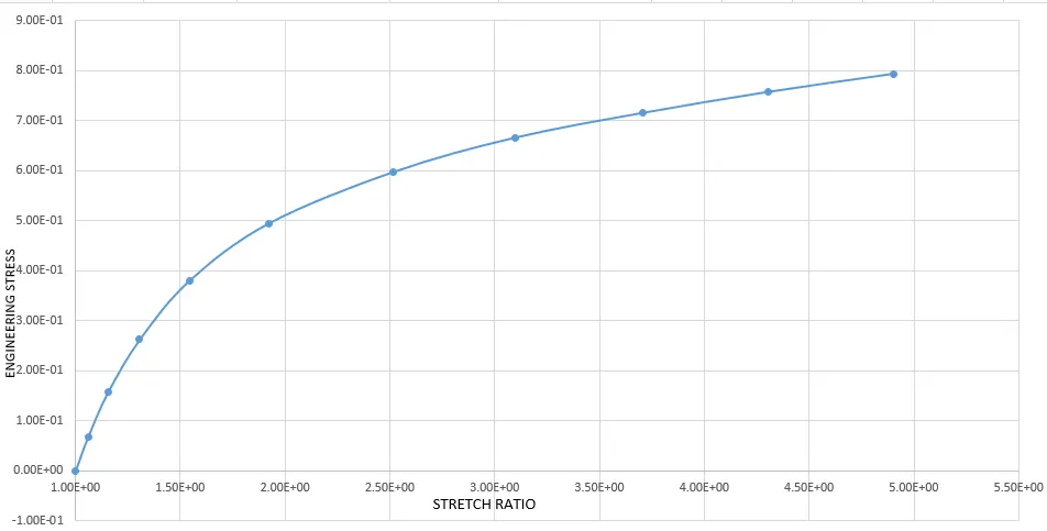
The Solid element formulation 1,-1,2,-2 gives similar results. The computational time for -2 is little higher and ELFORM 1 takes lowest computational time.
LINK FOR PROJECT FILES :elf 1 https://drive.google.com/drive/folders/19Xpy1QoRt9mnzdq3Vvcs_z-N3PSYAbRJ?usp=sharing
elf -1 https://drive.google.com/drive/folders/1Bd7HPNfrl9C4icOQvPyB5vo7prQiiaH6?usp=sharing
elf 2 https://drive.google.com/drive/folders/1UHx40cbUkZTy_fMMGvGcIWiJlspUbUfU?usp=sharing
elf -2 https://drive.google.com/drive/folders/13I3OcxMoI7-DreW0ykPcQS1w-SGWGx_Z?usp=sharing
CONCLUSION :
1. The Cube of 10x10x10mm is created and material is assigned.
2. Boundary conditions are created for a simple tensile test.
3. The Implicit control cards are used because it gives accurate solutions for simple components in non-linear analysis when compared to Explicit.
4. The true stress strain values are obtained from simulation of different solid element formulations and corresponding Engineering Stress , Engineering strain and stretch ratio values are tabulated.
5. The Engineering Stress vs Stretch ratio values are plotted in a graph upto stretch ratio 5 for all element formulations.