Week-6 Calculate the Stretch Ratio by comparing the ELFORM (-2,-1,1,2) with Ogden_Material Model.
Week-6 Calculate the Stretch Ratio by comparing the ELFORM (-2,-1,1,2) with Ogden_Material Model
AIM
Given is a Ogden material card which is hyperelastic (rubber).
Create a 10x10x10mm solid mesh and run a pure tensile run on it with stretch ratio of 5.
Compare different element formulations of solids 1,-1,2,-2 and plot engineering stress vs stretch values.
EXPLANATION
Since this simulation is happening at a really slow pace (quasi static) the inertial effects can be neglected we can consider implicit for the analysis.
Since this a hyperelastic material even though we are running it in implicit , we need steps and iterations to achieve the equilibruim.
Element formulations used are 1,-1,2,-2 for solids.
ELFORM 1 - underintegrated constant stress ; needs hourglass stabilisation; efficient and accurate
ELFORM 2 - Reduced integrated ; no hour glass stabilisation needed; slower than ELFORM 1; shear locking can occur
ELFORM(-1 )- Similiar to ELFORM 2 , but shearlocking is accounted for; efficient formulation (CPU time)
ELFORM (-2) - Similiar to -1 , more accurate, more computational cost.
Procedure
- Open the given ogden file > create a 10x10x10mm solid mesh using the shape mesher option.
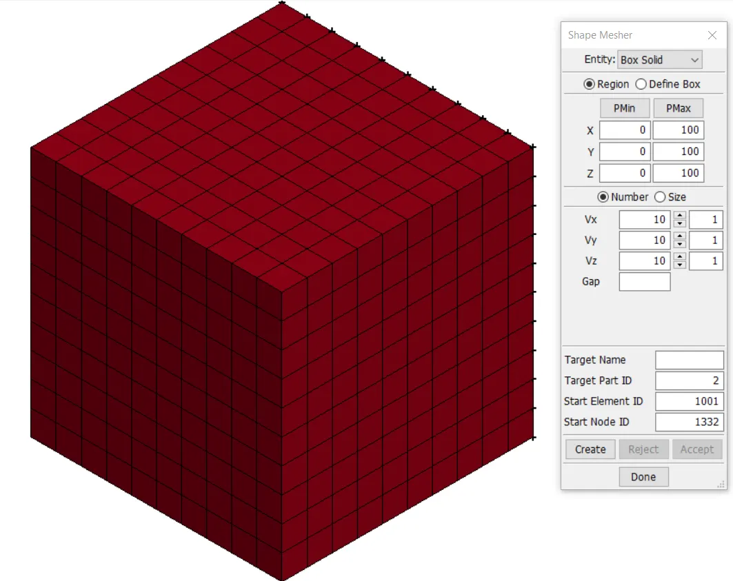
- Section is created using the solid with ELM formulation, the section and the given material card is assigned to the part created.
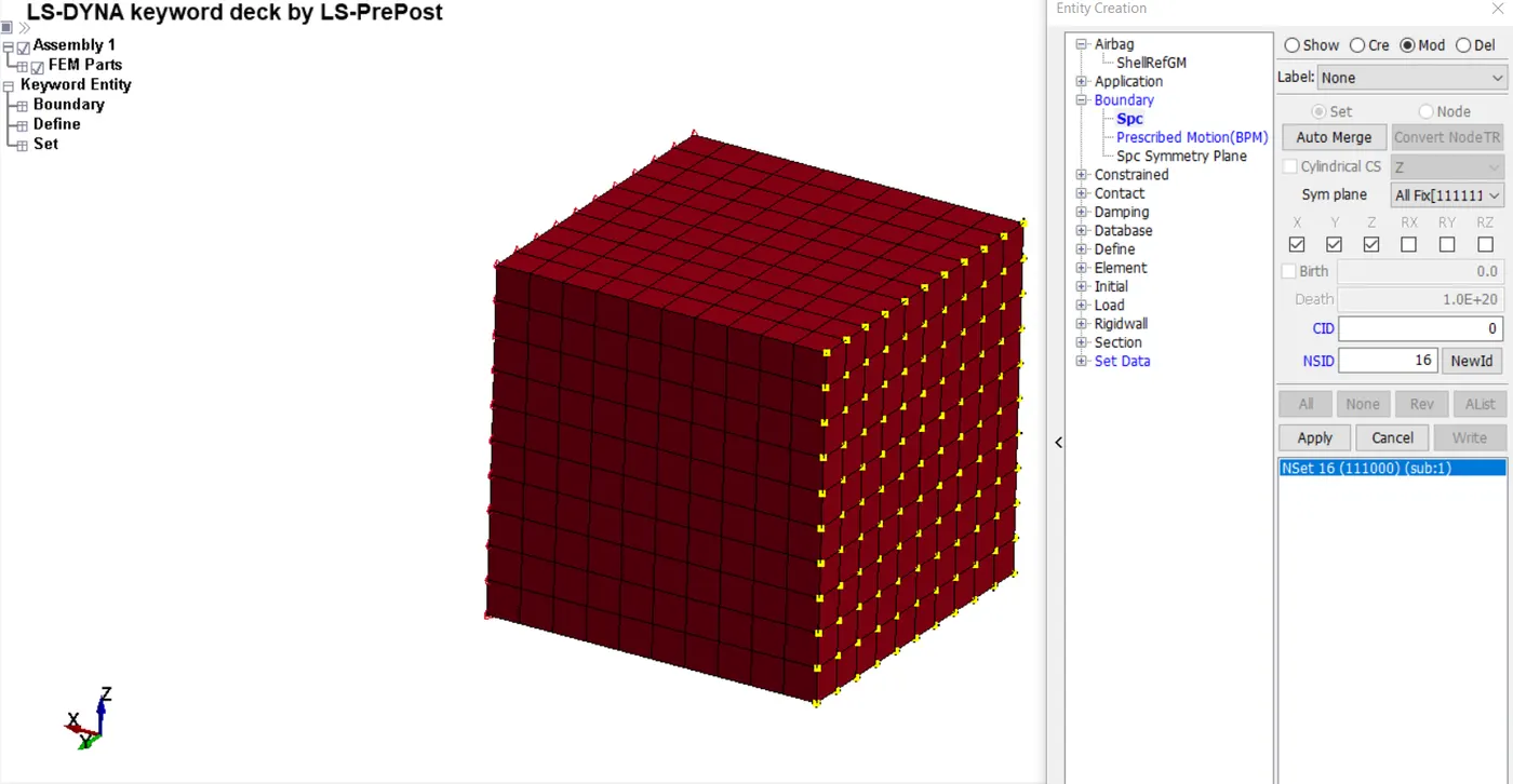
- Since this a tensile test has to done , part needs to be constrained on one face and pulled from the other face.
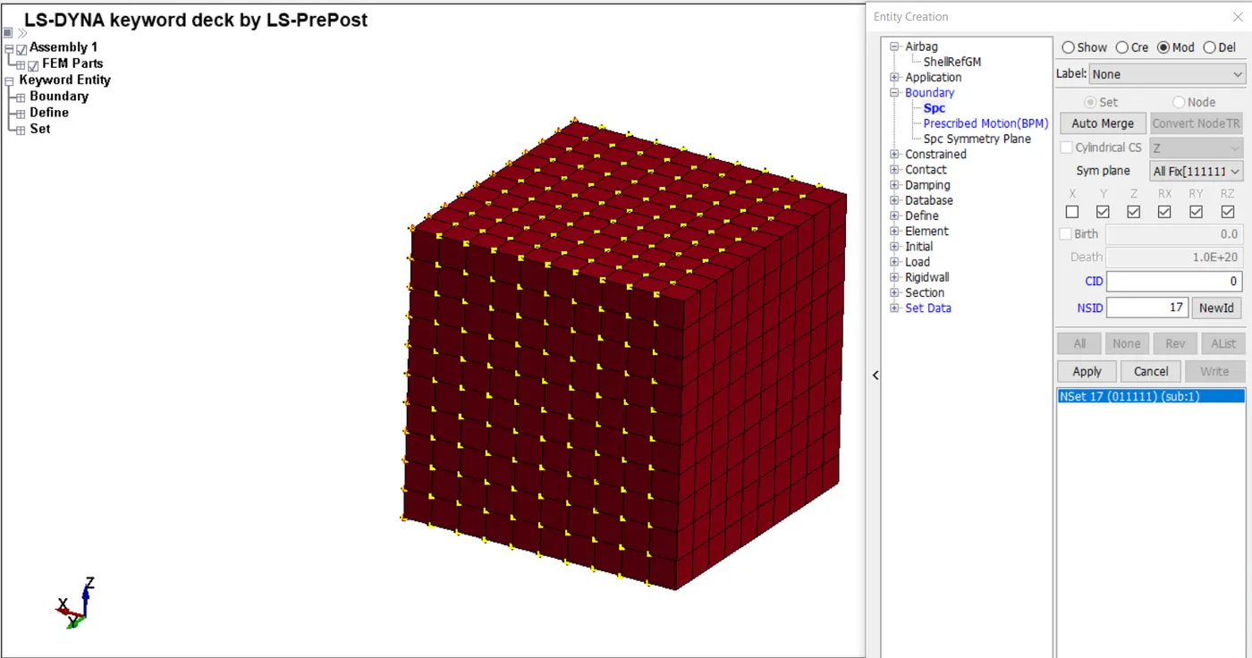
- For this case 2 SPC are created - one for holding one face with DOF as 111000 and rest of the part are give a dof 011111 (so it can be pulled in only X direction).
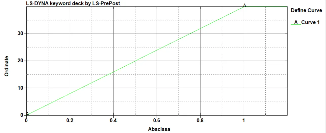
- Prescribed motion is applied in positive x axis and for achieving stretch of 5 , a displacement of 40mm is give to the other face of the solid mesh.
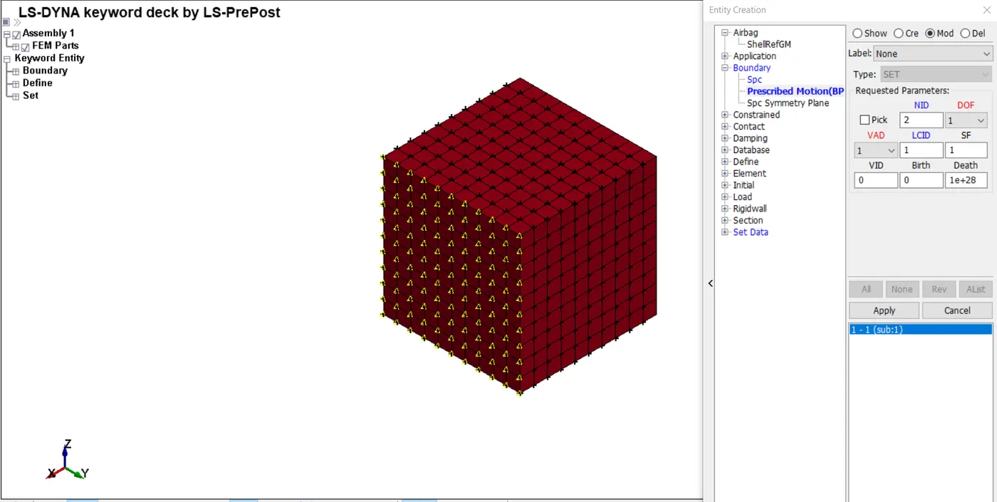
- Defined curve for displacement is given below, displacement is linearly applied at constat rate.
- We know that Stretch = 1 + Engg strain
=> 5 = 1 + (Displacement or change in length / 10)
=> Displacement = 40mm
- To make sure that LS Dyna runs the model in implicit analysis control implicit cards needs to be defined.
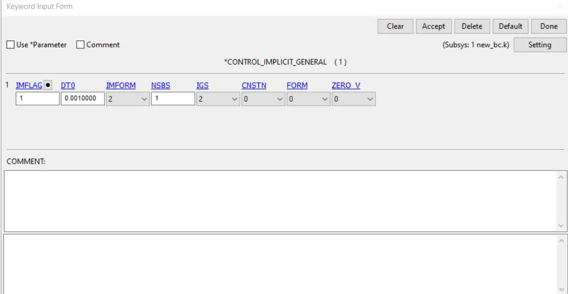
- Implicit general > parameter IMFLAG = 1 , so that implicit code is called, to be precautious DTMIN (intial time step size ) = 0.001ms is given.
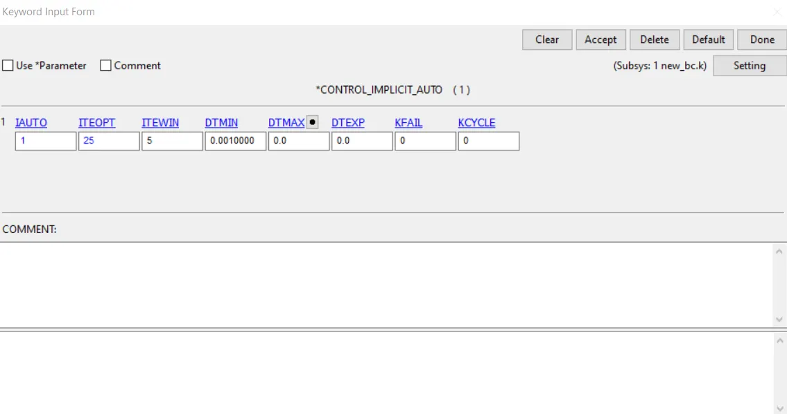
- Implicit Auto is card used so that the code can automatically converge the solution at faster rate by reducing the time step (Manual control of iteration per each step ITEOPT)
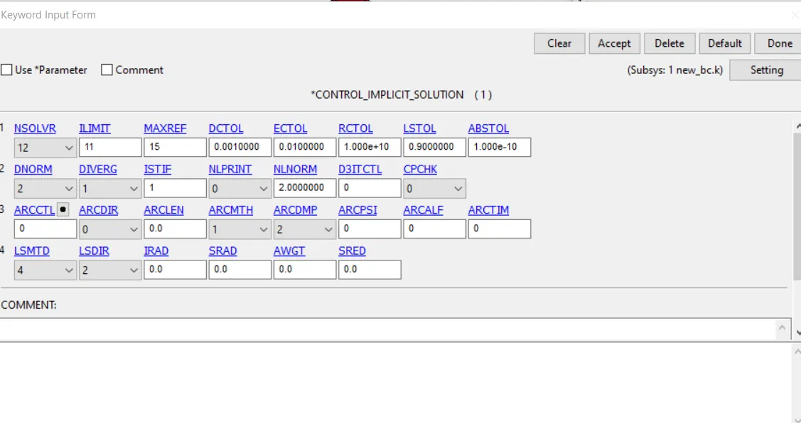
- Implicit Solution > Nsolvr is set to 12 as the material is very non linear in nature ; DCTOL (displacement tolerance) = 0.001 ; Implicit solver default parameters are used.
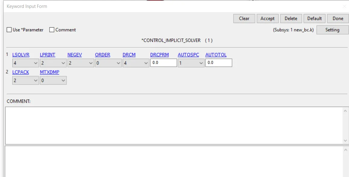
- Control termination is given as 1 ms.
- Output/Database cards > GLSTAT and D3Plot is requested ; Extent Binary card is also requested with STRFLG = 1 for strain data .
- Run the model with memory as 1 MWords.
Results
We know relationship (before necking) => True stress = Engg stress ( 1 + engg strain)
=> True Strain = ln ( 1 + engg strain) = ln (stretch)
=> Stretch = 1 + engg strain
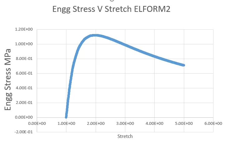
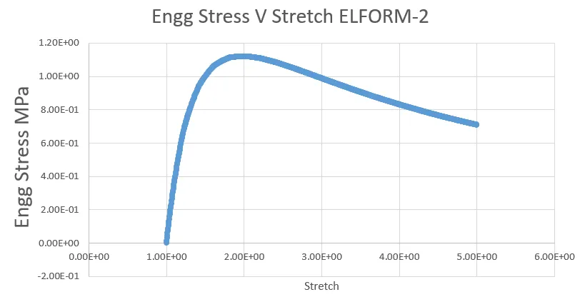
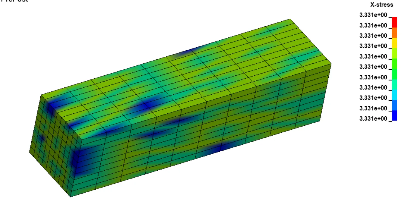
Post processing plotting x stress and mean x strain for all the Element formulation , true stress and strain can be found out .
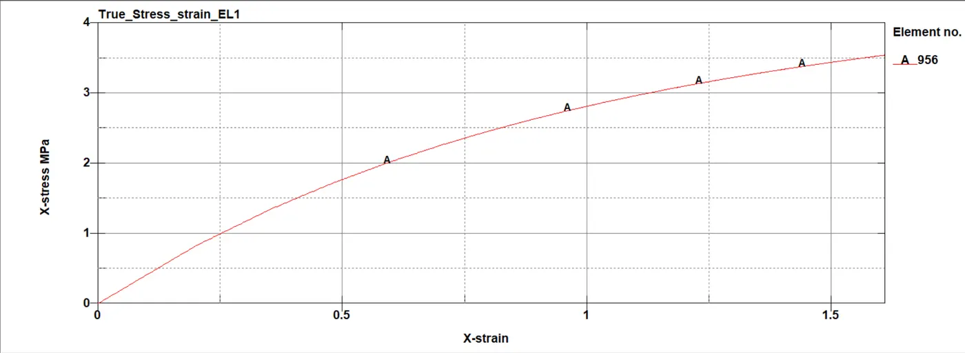
- The above graph is true uniaxial (x) stress - strain curve of the odgden material with ELFORM 1 from ls dyna.
- From this Engg stress and strain > then stretch ratio can be found out.
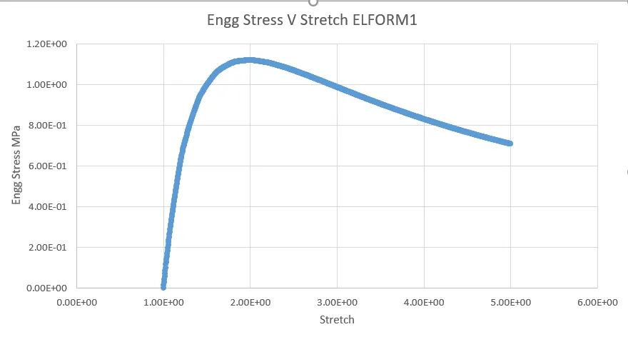
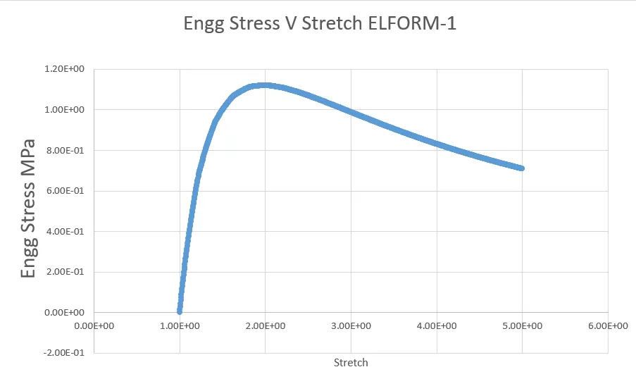
- Using excel the Engg stress and stretch ratio can be compared.
Conclusion
- There is no much difference in values of stresses between the formulation for stretch of 5.
- Usage of different element formulation depends on accuracy or effiency (cpu time) requirements. In this case a large variation could not be found, when model is large enough we can notice a significant difference in the computation time. ( Integration points and hourglass controls)
- Files Drive Link - https://drive.google.com/file/d/1N4GyppE5lH6Irk7ZcA7JcsKlCeuAgu38/view?usp=sharing