Deploying connections for rear door of a car in NASTRAN deck
Objective:
The objective here is to deploy connections for the FE model of the rear door of a car for NVH. These connections will be done in NASTRAN deck in ANSA.
Procedure:
Car door is a very important assembly as it has many connections in one single subsystem. In this project we will see the important connections and deploy them for the rear door of a car for NVH. And NASTRAN is the industry leading software for NVH analysis. Connections are done in FE model to connect and constraint different components with each other. Following are some important connections to be made for a door assembly.
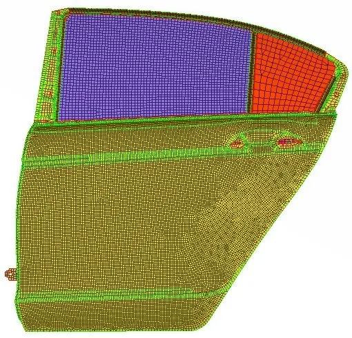
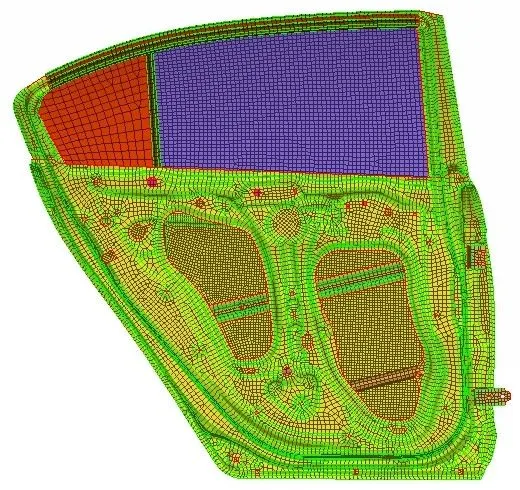
First the given rear door FE model is imported into ANSA. The image below shows the given FE model of the rear door of car.
Now let's see the connections that need to be deployed.
Bolt
The bolt connection is used to connect two or more parts together and is modelled with cluster of rbe2 elements. The rbe2 element is a rigid element with infinite stiffness. Image below shows a region where a bolt connection needs to be done.
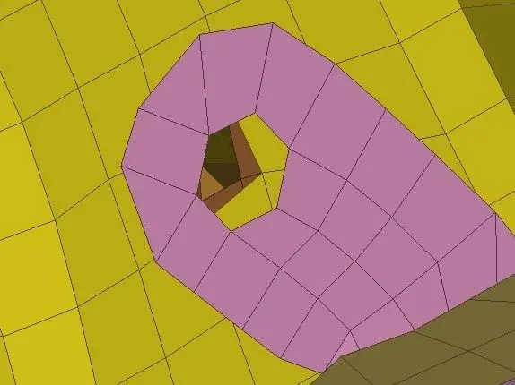
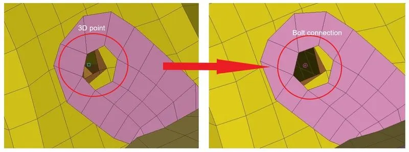
There are three components that need to be connected. To model a bolt connection here, first a 3D point is created by going to Topo module>Points>On COG and any one hole is selected. Next, the created 3D point is converted into a bolt connection by going to Assembly>Convert>3D points and the point is selected and in the next panel, Bolt is selected as the connection type and a bolt connection is created as shown in image below.
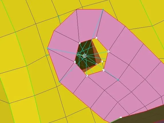
Next step is to realize this connection. To do so, go to Assembly>Connections Manager and the select the bolt connection. In the connections manager, select the PIDs to be connected. Maximum four PIDs can be connected namely P1,P2,P3, and P4. Here, we only need to connect three parts so, these three PIDs are selected and Bolt is configured as the FE Rep Type. And search distance is given as 10. The image below shows the realized bolt connection.
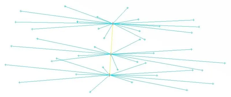
The realized connection is isolated and shown in image below. This type of bolt representation is called as bolt and stem representation as it includes a separate element to represent the stem of the bolt. All are rbe2 elements, with the yellow coloured element in the middle representing the stem of bolt. The red coloured nodes are master nodes and all other nodes are slave nodes.
Hinges
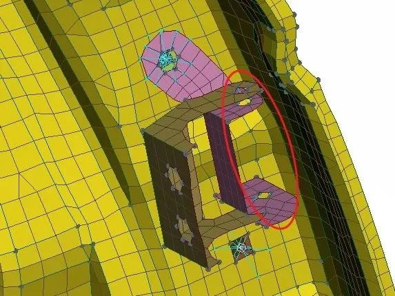
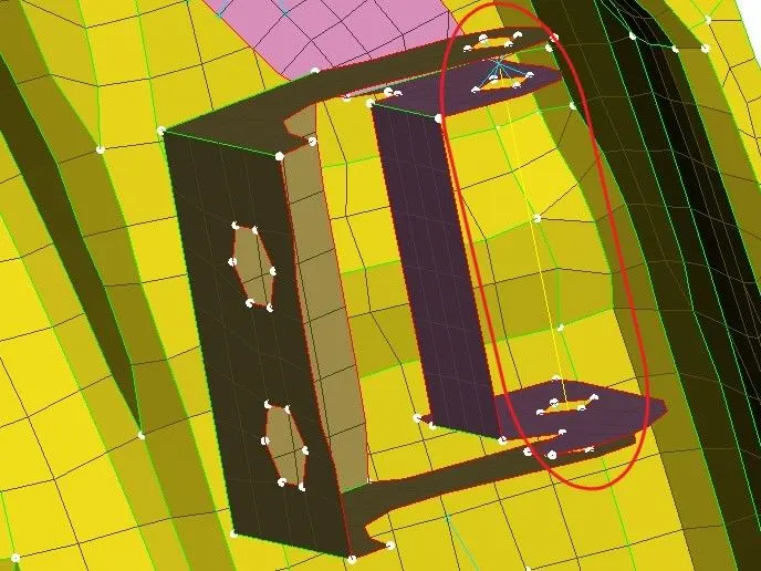
Next, connections are deployed for the door hinges which are also bolt connections. The region where connection need to be deployed is shown below. Brown and purple coloured parts are the hinges. Brown coloured part will be attached to the vehicle body and purple coloured one is attached to the door.
This time these bolt connections will be modelled in a different way. First, a bolt connection is made between the two parts of the hinges. To do so, switch to NASTRAN deck module and go to Elements>RBE2>multi nodes and select all the nodes to be constrained. And create the connection. Similarly, same type of connection is made for the lower side of the hinge. The final connection created is shown in image below.
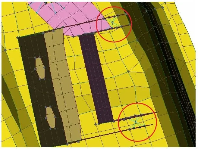
This type of connection is called as bolt cluster representation. It consists of only one master node and stem is not represented here. Next, a two node rbe2 element is created using the two master nodes of the created clusters. The final hinge connection is shown below,
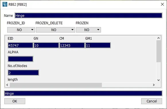
Right now, the created rbe2 element are constrained for all dof along the x,y, and z axis. But we know the door needs to be able to freely rotate and open. To check the dof of the rbe2 element, got to Elements>Info and click on the two node rbe2 created. A dialog box open, where the CM parameters shows the dof constrained. Parameter 123456 means that all 6 dof along the x,y, and z axis are constrained. To enable roatation around the z-axis, number 6 is deleted from CM.
Next, other regions are identified with bolt connection and multi node rbe2 cluster is deployed to realize the bolt connection.
Spot Weld
Spot weld is another type of connection found in the car door assembly. A spot weld is modelled with a rbe3-Hexa-rbe3 element. Image below shows one such region where spot weld connection needs to be deployed.
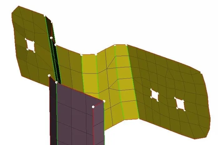
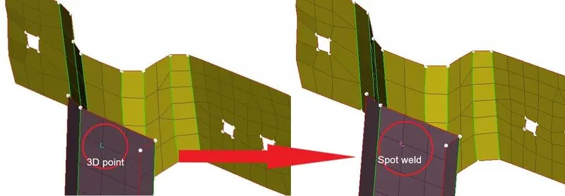
To deploy a spot weld connection, we first need to create a 3D point. And then that 3D point is converted to a spot weld by going to Assembly>Convert>3D points and the point is selected and in the next panel, spot weld is selected as the connection type and a spot weld connection is created as shown in image below.
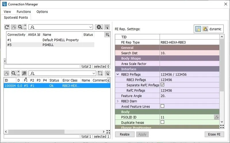
Next step is to realize this connection. To do so, go to Assembly>Connections Manager and the select the spot weld connection. In the connections manager, select the PIDs to be connected. The image below shows the parameters used to create a spot weld connection.
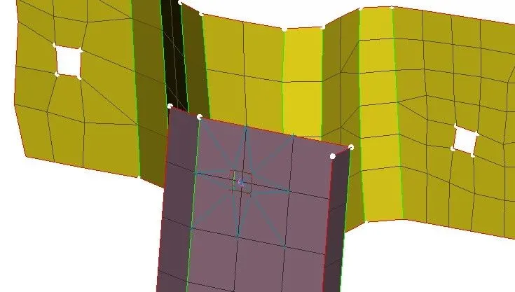
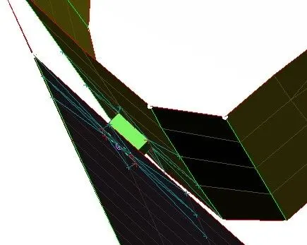
The image below shows the realized spot weld connection,
Door Handle
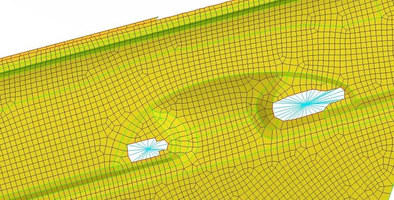
The standard procedure to model the door handle is to capture the door handle as a point mass only. The door handle region is shown in the image below.
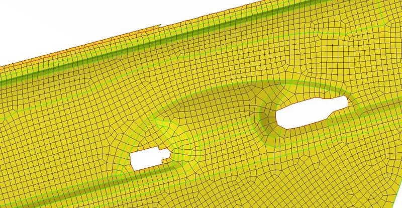
First, a rbe2 cluster is created for the holes where door handle would be connected by going to Elements>RBE2>multi nodes in NASTRAN module, as shown in image below.
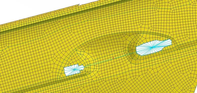
Next, again rbe2 elements are created by selecting the two master nodes of the created rbe2 cluster, as shown below.
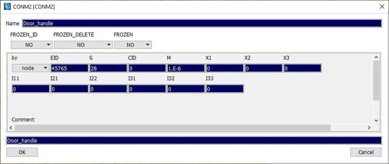
Next, a mass element is created at the center node of the newly created rbe2. Mass element is represented by CONMi in Nastran. To create a CONMI at this node, go to Elements>CONMi>CONM2>nodes and the center master node is selected. In the next dialog, 100g (1e-6 tonnes) mass is given as the value to parameter M (mass).
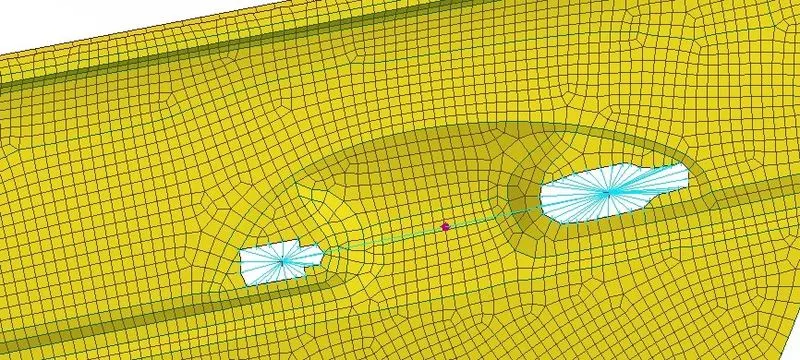
The final connection for door handle is shown below, where the bright purple node represents the mass element.
Glass connection
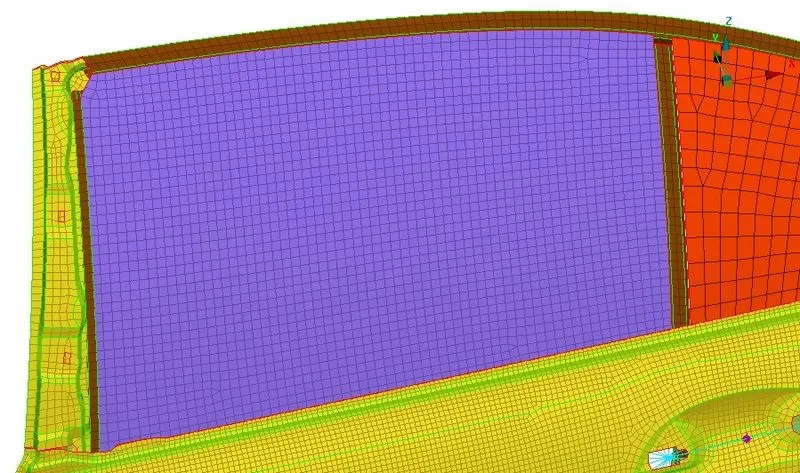
This is a very critical connection in door assembly as the glass is a brittle material. It is a standard practise to model the glass as fully closed window. In a real case, a weather strip is applied across the window parameter and holds the glass between itself. To connect the glass FE to the door FE model, this weather strip is modeled using the rbe3-CBUSH-rbe3 elements. This element has damping and elastic properties along all three axis. To deploy this connection, we first need a connection line. But there is no CAD data avialbe in the current file. So, line data is extracted from the FE model itself. The image below shows the Glass FE model in blue and orange colour.
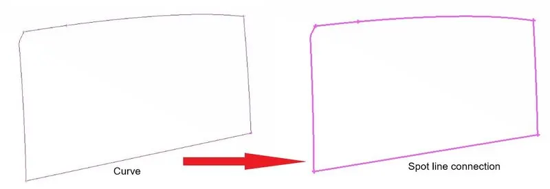
This is done by creating a curve around the Glass FE using the Feat2Curve tool available at Perimeters>Feat2Curve under the Mesh module. Then the created curve is converted to connection line by going to Assembly>Convert>Curves and the created curves are selected and spot line is selected as the connection type.
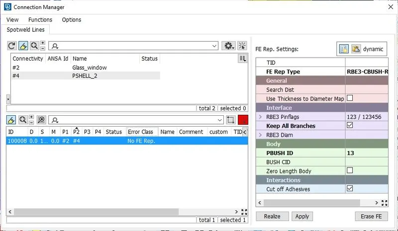
Next, the connections are realized by going to Assembly>Connection manager and the spot line is selected. And, in the connection manager, the components to be connected are selected and the parameters configured as shown in image below, Search distance is also configured with a value 50.
The image below shows the part of realized connections,
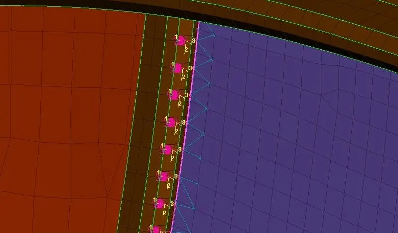
Similalry, connections are deployed for other three sides and the second glass also. Currently, the CBUSH connections are automatically oriented. Next all the CBUSH elements are aligned along the global coordinates which is a standard practise.
The image below shows the zoomed out view for all the CBUSH connections deployed.
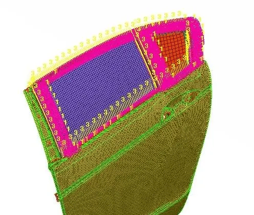
All the bright pink elements represents the CBUSH elements.
Conclusion:
All the necessary connections were succefully deployed for the rear door assembly.