DEPLOYED NECESSARY CONNECTIONS FOR A FE MODEL - REAR DOOR OF A PASSENGER VEHICLE using ANSA
AIM
To deploy necessary connections for the given rear door FE model.
GIVEN DATA
FE model of rear door
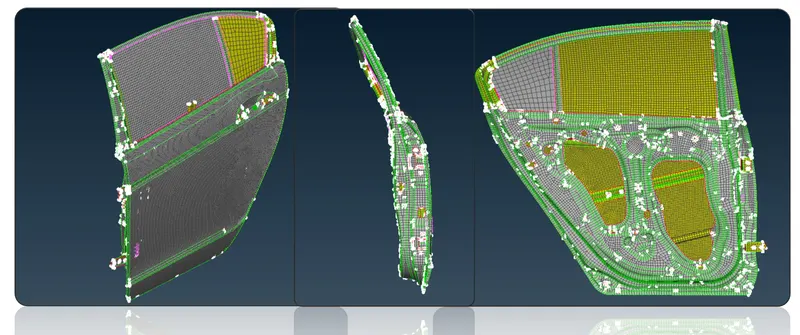
Figure 1 - Given FE Model
CONNECTION
- Connections are nothing but representation of bolts, welds, rigid body, etc. in a FE model.
- Here I have deployed various necessary connections.
- In this FE model, I have used BOLT connection, WELD connections, etc. as per the given cad data also assumed the welded area & deployed weld connections as the seam weld raw data has not given in this model.
- Types of connections used here are,
- Bolt connection.
- Weld connection.
- Seam weld
- Spot weld
- C- Bush connection element
- Concentrated Mass element connection (CONMi)
BOLT CONNECTIONS: (No property element)
RBE2 element (Manual representation for bolt or rigid body elements):
- I have gone with manual representation for bolt connection since it looks easy for me to deploy those connection.
- In RBE2 element master nodes are independent nodes & slave nodes are dependent nodes.
- Slave node will behave as per the behaviour of the master node.
- The different kinds of RBE2 elements are,
- Two nodded RBE2
- To represent the stem of the bolt.
- Many nodded RBE2
- Set
- Two nodded RBE2
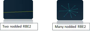
Figure 2 - RBE2 Elements
Concentrated Mass element connection (CONmi):
- Apply concentrated point mass load
- The entered mass should be in terms of tonns.
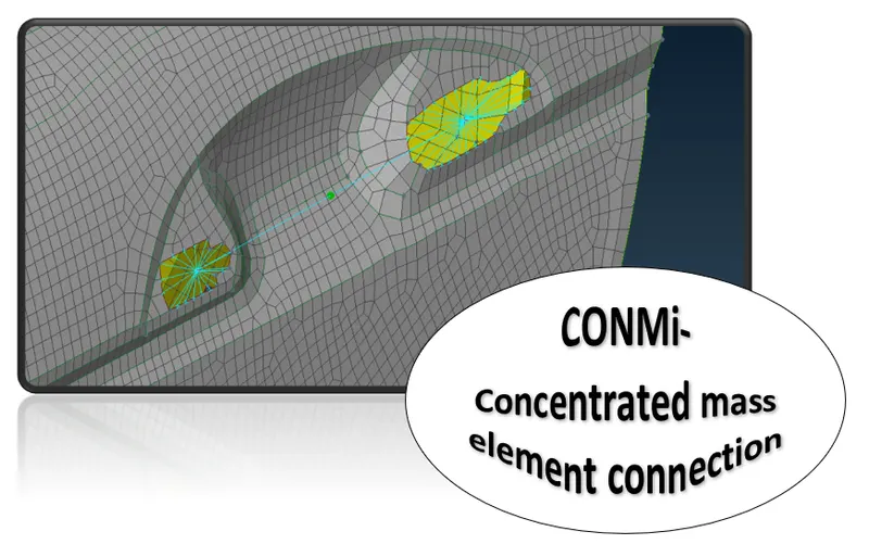
Figure 3 - CONMi
WELD CONNECTIONS:
- Seam weld connection.
- Spot weld connection.
Seam weld:
Overlap shell element - To weld parallel sheet metal component.
Y – joint shell element – To weld perpendicular sheet metal component.
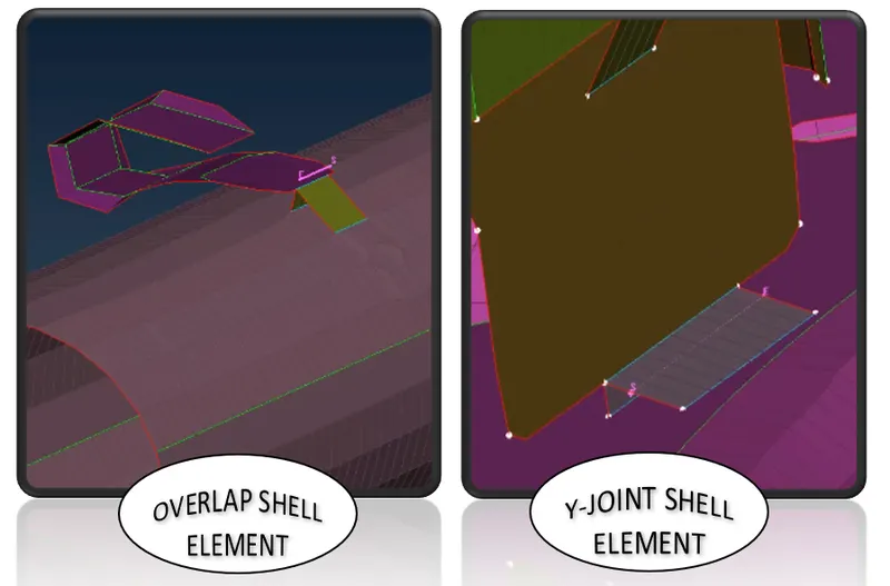
Figure 4 - Seam weld (Shell elements)
Spot weld :
RBE3 Hexa RBE3 element (Solid element)
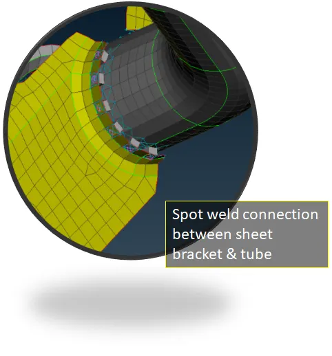
Figure 5 - Spot weld
C BUSH ELEMENT
C Bush element is generally a spring element which will be having damping co-efficient or stifness value in three different direction.
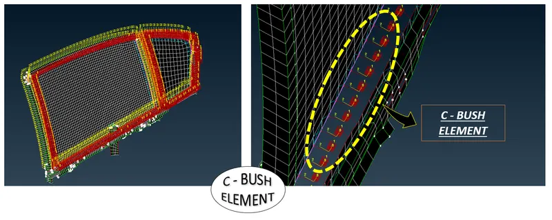
Figure 6 - C BUSH Element
PROCEDURE
Steps to deploy bolt connections (RBE2 elements): In this model i have gone with manual bolt connection RBE2 element
- Step 1 - GO to NASTRAN deck ---> Elements ---> RBE2 --> Many nodes
- Step 2 - Select slave nodes (By selecting the nodes of the holes - using loop will select the entire nodes on hole in a single shot) --> Next (Master node will be seen at centre of the hole) ---> Finish ( change to Ask always --> It will take to model browser so to save the connections into the new group and rename it as connections so it will be easy to visible or editing) ---> Now the RBE2 element will be deployed.
- Step 3 - Repeat the step 2 for other parallel holes.
- Step 4 - Now to connect these paralell holes. Go to NASTRAN deck ---> Elements ---> RBE2 --> Two nodes --> select the master nodes of the holes --> Finish --> Now the yellow line will be connected between the two master nodes of the parallel holes. These yellow line will represent the stem of the bolt.
- So To represent the stem of the bolt RBE2 Two node is used.
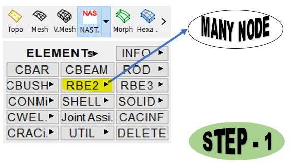
Figure 7 - Steps to deploy bolt connections (STEP - 1)
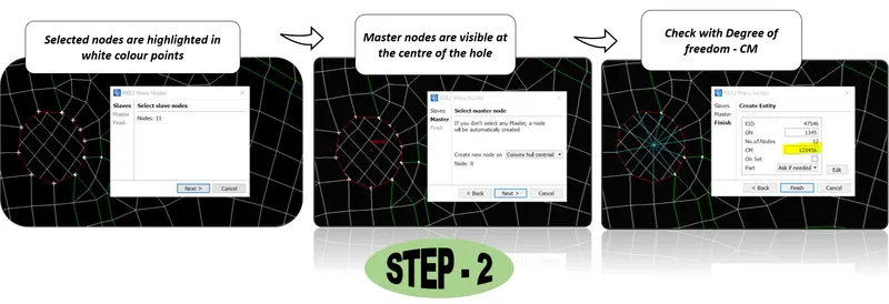
Figure 8 - Steps to deploy bolt connections (STEP - 2)
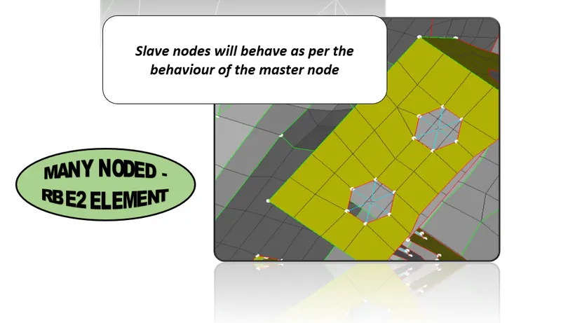
Figure 9 - Many Noded RBE2 Element
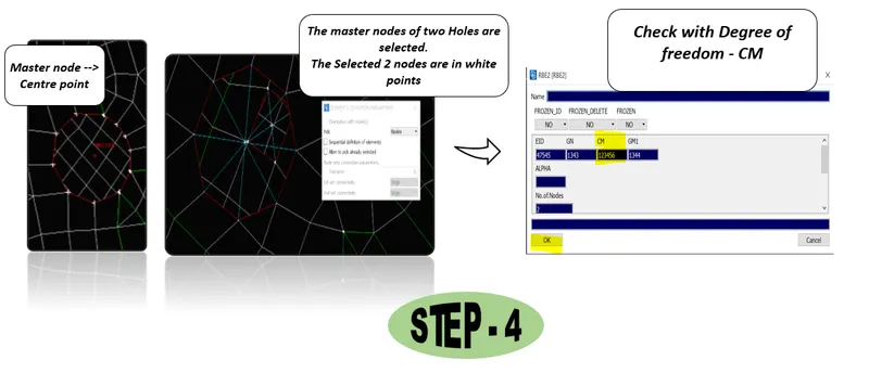
Figure 10 - Steps to deploy bolt connections (STEP - 4)
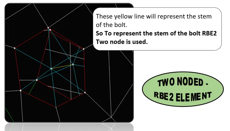
Figure 11 - Two Noded RBE2 Element
Steps to deploy bolt connections on DOOR OPENING & CLOSING JOINTS:
- While deploying Two noded RBE2 element to represent the stem of the bolts at those opening & closing pin joints of doors as shown in below figure has to be free from rotational Z axis.
- The Degrees of freedom for the rotational axis (Z) of a door for opening and closing should not be constrained. So to do that In CM -123456 we have to remove the 6 and the CM - should be 12345 as shown below figure. (CM- DEGREES OF FREEDOM)
- 123 (XYZ) - Linear translation
- 456 (XYZ) - Linear Rotational
- Since, here the Z rotational axis should be freed so we have entered CM - as 12345 which means (XYZ LINEAR TRANSLATION & XY ROTATIONAL ARE ARRESETED OR CONSTRAINED)
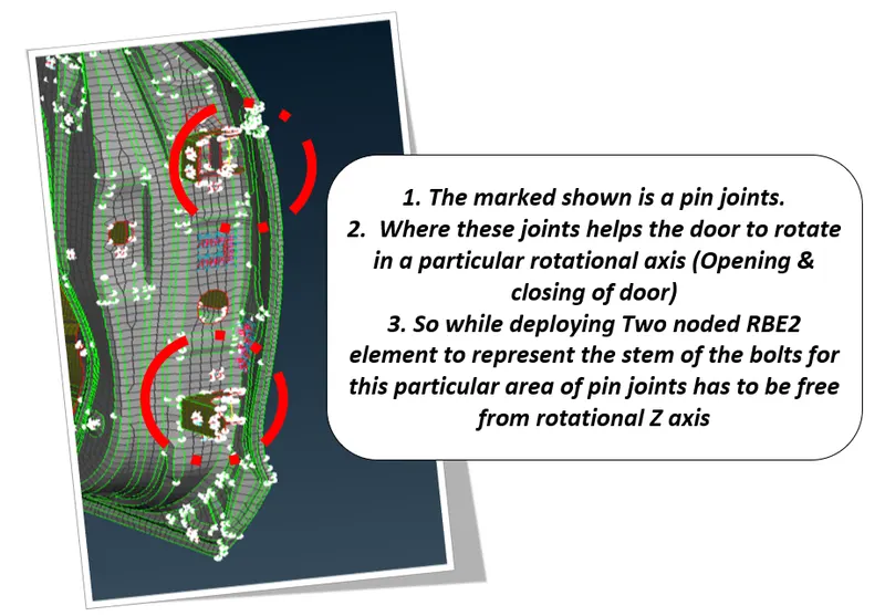
Figure 12 - Steps to deploy bolt connections on DOOR OPENING & CLOSING JOINTS
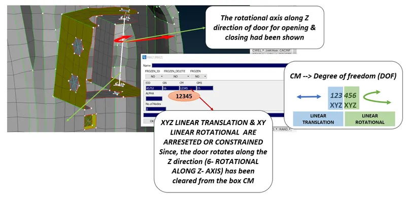
Figure 13 - Steps to deploy bolt connections on DOOR OPENING & CLOSING JOINTS
Steps to deploy connections on DOOR HANDLE:
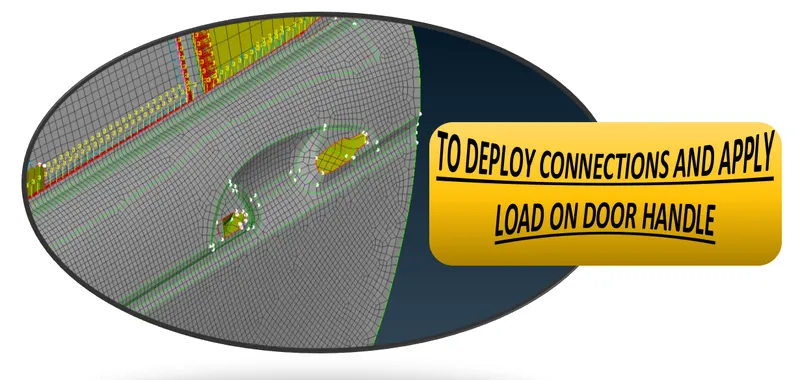
Figure 14 - To deploy connections on DOOR HANDLE
- Step 1 - Deploy Many noded RBE2 element for both the holes separately.
- Step 2 - Again use many noded RBE2 element by selecting the master nodes of two holes.
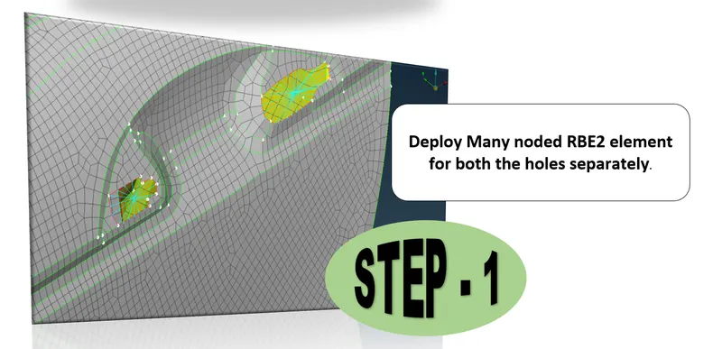
Figure 15 - Steps to deploy connections on DOOR OPENING & CLOSING JOINTS (STEP -1)
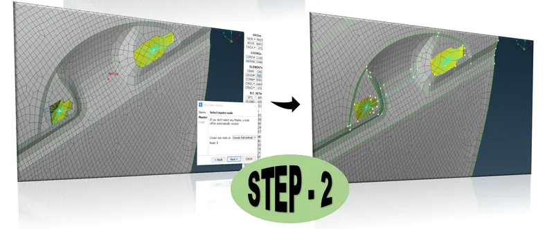
Figure 16 - Steps to deploy connections on DOOR OPENING & CLOSING JOINTS (STEP -2)
To apply Concentrated mass element connection(CONMi) on DOOR HANDLE:
- Step 1 - Go to NASTRAN deck ---> Elements ---> CONMi (Definition of concentrated mass element coonection) ----> Select on centre point & do middle click.
- Step 2 - Now, CONMi card will be open. Enter the Mass value. The entered mass value should be in terms of tons.
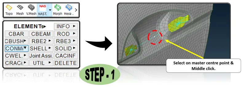
Figure 17 - To apply Concentrated mass element connection(CONMi) on DOOR HANDLE (STEP -1)
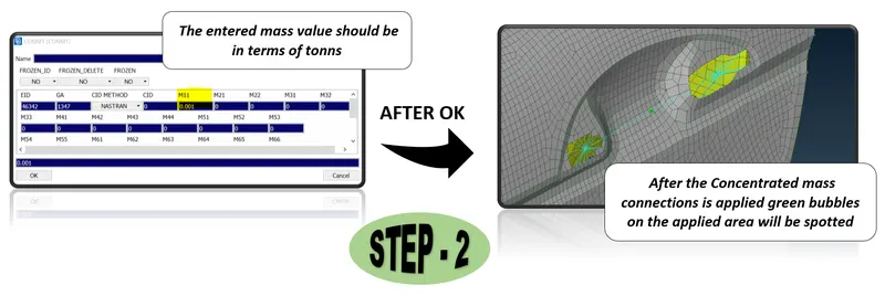
Figure 17 - To apply Concentrated mass element connection(CONMi) on DOOR HANDLE (STEP -2)
CONNECTIONS BETWEEN GLASS & GLASS SLIDING RAIL OF A DOOR:
- While deck preparation, FE model of glass is to be captured by closed position and RBE2 connections has to be deployed between Glass & slide rail for NVH study.
- Move the FE model of sliding rail upto the glass in closed position.
- The procedure for modeling & deploying connections between such glass & slide rail part are as follows,
- Step 1 - Go to mesh --> Grids ---> Mv free ---> select the axis to be moved freely ---> Drag the mouse. Move the FE model of sliding rail upto the glass in closed position.
- Step 2 - Now deploy RBE2 connections between those slider & glass as shown in below figure.
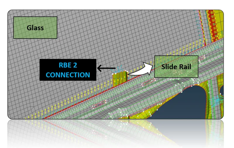
Figure 18 - CONNECTIONS BETWEEN GLASS & GLASS SLIDING RAIL OF A DOOR
To apply C - BUSH connections on GLASS PART OF THE DOOR PANEL:
(CONNECTION FOR WEATHER STRIPS)
C - Bush is generally a spring element which will be having damping coefficient or stiffness value in three different direction.
- Step 1 - Get line data from FE Model:
- To do that Go to topo --> curves ---> cons2curve. By following this step the damping line will be created.
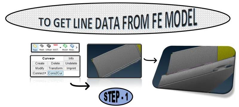
Figure 19 - C BUSH --> CONNECTIONS FOR WEATHER STRIPS (STEP 1)
- Step 2 - Connect the curves into single curve by using connect --> multi (Go to topo --> curves ---> connect ---> Multi).
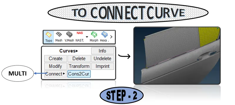
Figure 20 - C BUSH --> CONNECTIONS FOR WEATHER STRIPS (STEP - 2)
- Step 3 - For below region alone use two curves for deploying C bush connection. For that transform ---> copy the existing curve created on step 2 as shown in below figure.
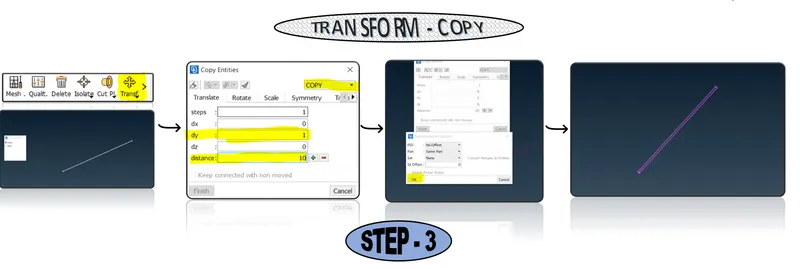
Figure 21 - C BUSH --> CONNECTIONS FOR WEATHER STRIPS (STEP - 3)
- Step 4 - Convert those curves into spot line (Define spot line separately):
- To do that GO TO --> Convert --> Curve ---> Select the curve to be converted ---> Connection type - Spot line --> OK
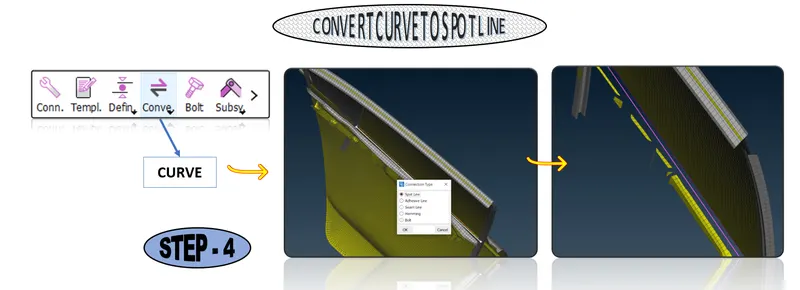
Figure 22 - C BUSH --> CONNECTIONS FOR WEATHER STRIPS (STEP - 4)
- Step 5 - To Realize spot line:
- GO TO ---> Connection manager --> select the spot line ---> middle click on mouse ---> Connection manager window will pop-up
- In connection manager,
- FE Rep Type --> RBE3 C BUSH RBE3
- Enter spacing value (S) of each bush.
- Select P1 & P2 by clicking F1 button.
- Enter search distance
- Select Keep all branches.
- Create and select P Bush ID by entering Shift+?
- Click on apply & Realize . Now the C- Bush for the selected spot line will be realized successfully as shown in below figure.
- Repeat the steps 1 to 5 for every side of the glass to represent the weather strip by C- Bush connection.
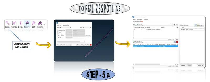
Figure 23 - C BUSH --> CONNECTIONS FOR WEATHER STRIPS (STEP - 5 a.)
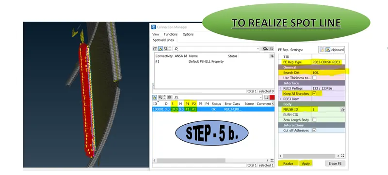
Figure 24 - C BUSH --> CONNECTIONS FOR WEATHER STRIPS (STEP - 5 b.)
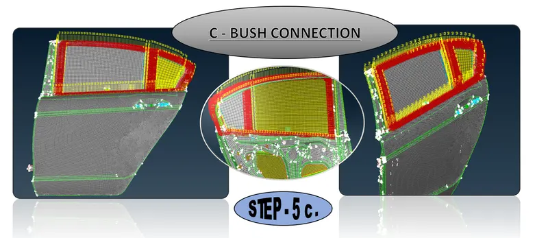
Figure 25 - C BUSH --> CONNECTIONS FOR WEATHER STRIPS (STEP - 5 c.)
Figure 26 - C BUSH
- Step 6 - Finally change the Orient & give CID value:
- Press F12 key to open Data base window.
- Go to elements ---> double click on C - Bush.
- In show/hide column select list fields & select Orient & CID to get visible on C Bush data base list.
- Now modify the Orient from vector to Corordinate. This change is done to change the co ordinate from local axis to global model axis.
- Enter the CID value to 0.
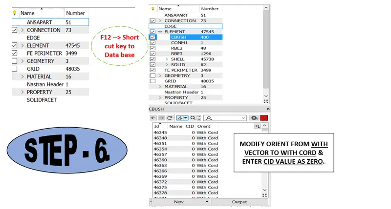
Figure 27 - C BUSH (STEP - 6)
WELD CONNECTIONS FOR JOINING OTHER SHEET METAL PARTS:
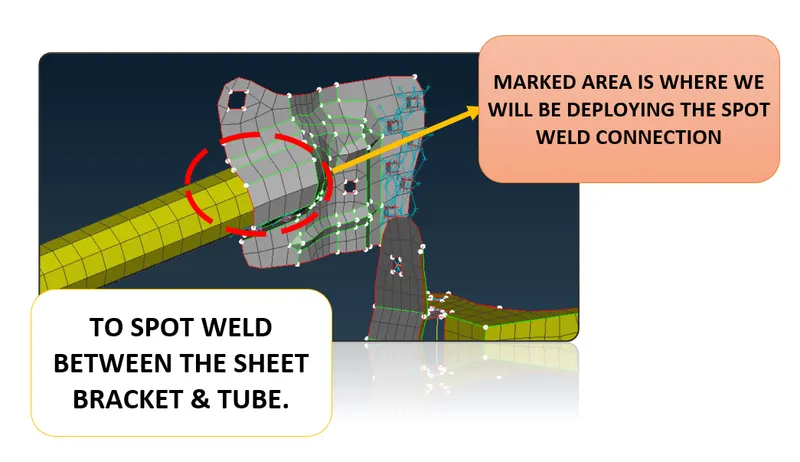
Figure 28 - SPOT WELD CONNECTION
- Step 1 - Create 3D point:
- Go to Topo --> Points ---> On COG ---> Select the EDGE of the FE model to be spotted ----> Middle click on mouse. Now the 3D point will be created on centre of the box selected as shown in below figure.
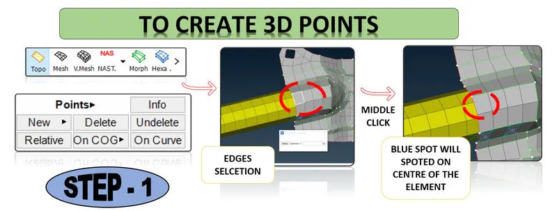
Figure 29 - SPOT WELD CONNECTION (Step 1)
- Step 2 - Covert 3D points to spot weld:
- Go to Convert ---> 3D points ---> middle click on mouse. Now the spot weld symbol will be seen visible as shown in below figure.
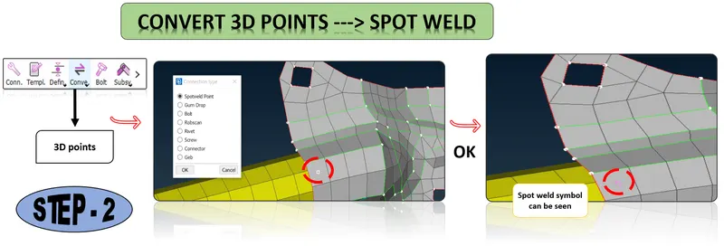
Figure 30 - SPOT WELD CONNECTION (Step 2)
- Step 3 - Realize spot weld :
- GO TO ---> Connection manager --> select the spot ---> middle click on mouse ---> Connection manager window will pop-up
- In connection manager,
- FE Rep Type --> RBE3 HEXA RBE3
- Select P1 & P2 by clicking F1 button.
- Enter search distance
- Create and select WELD ID by pressing on Shift+?
- Click on apply & Realize . Now the Spot weld for the selected spot will be realized successfully as shown in below figure.
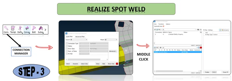
Figure 31 - SPOT WELD CONNECTION (Step 3)
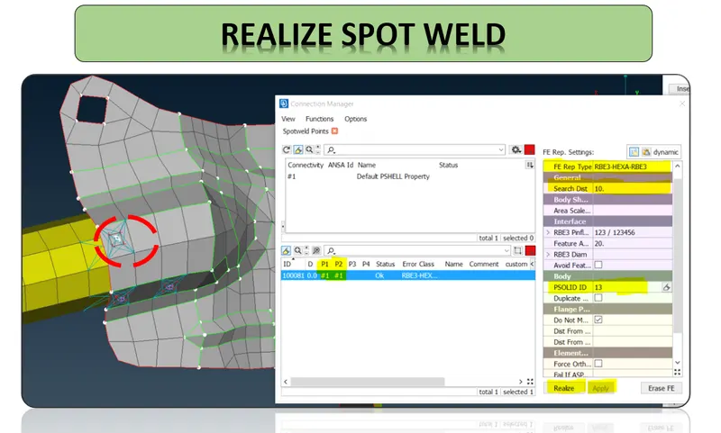
Figure 31 - REALIZED SPOT WELD CONNECTION
CONCLUSION
Necessary connections for the given rear door FE model has been deployed successfully.
LEARNING OUTCOMES
At the end of this challenge, I can able to deploy necessary connections for automotive components.