Week 6
CONNECTIONS FOR NVH ANALYSIS IN ANSA
All connection types are characterized by their type, id, location in space and some additional information concerning geometric features, such as diameter, width or height. There are three types of connections based on the order of the connection's shape: -
- connection_0d are connections that can be represented by a single location in space. Examples of these are spot welds,rivets, and bolts.
- connection_1d are connections that can be represented by a curve in space. Examples of these are seam welds, pump-able adhesive, and weatherstrips.
- connection_2d are connections that can be represented by a surface in space. Examples of these are die-cut adhesive and windshield bonding.
AIM: -
- Define the connections for different sub-systems of the rear door.
- Ensure proper connections are deployed between the parts.
PROCEDURE: -
- Open the "Rear-Door.nas" Nastran file by File>Input>Nastran option.
- The imported model is a FE model of the rear door assembly, we need to connect different sub system using suitable connectors available in ansa. The door system consist of door lock mechanism, hinge mechanism and the door glass slider mechanism.
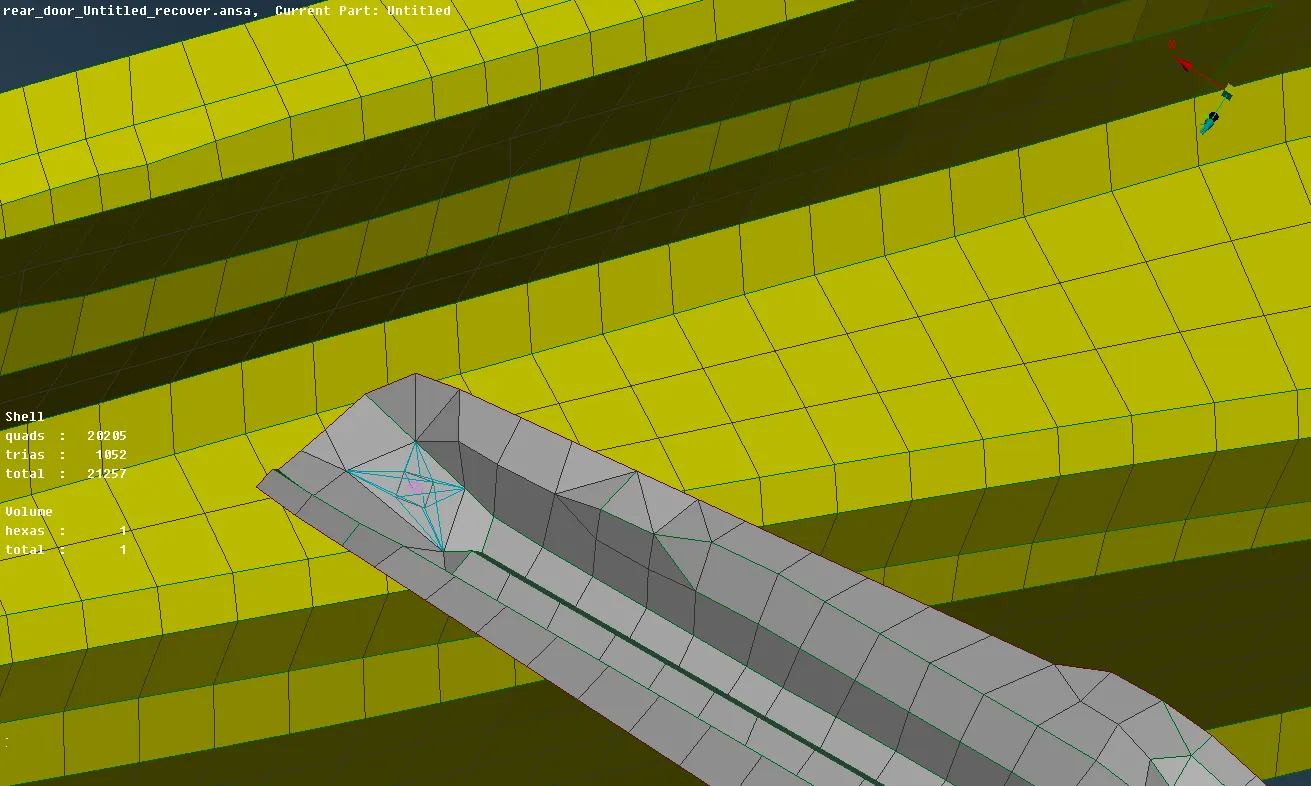
Bolt Connection: We will create a bolt connection between the door hinge and door body. A point is created using Topo>On COG>Edges option. Now convert those 3d points to bolts. To realize the connection go to connection manager, a connection manager window opens. Select the number of parts as P1, P2 and P3. Any connection in ansa will not have more than four attaching parts.
- Put Fe Representation type as Bolts, zones as In/out X and Body type as RBE2. Click Apply and Realize to create the rigids.
- Since the complete body is not available we will create a RBE2 connection with door hinge. Also the hinge should not restrict all degrees of freedom. The door will rotate along global Z direction. In order to make the rotation possible we will remove the Z axis rotational by Nastran Deck>Elements>Info tool.
- One difference between the RBE2 and RBE3 element is that in RBE2 the slave nodes are forming the spider and the center node will be a master node.RBE3 has center node as slave node and the other nodes will be dependent nodes. If there are no spaces or holes for connection, we assume that the parts are connected to each other. Go to Nastran Deck>Elements>RBE2>Many Nodes and create a cluster RBE2. It will make the area rigid and it will make itself as connection.
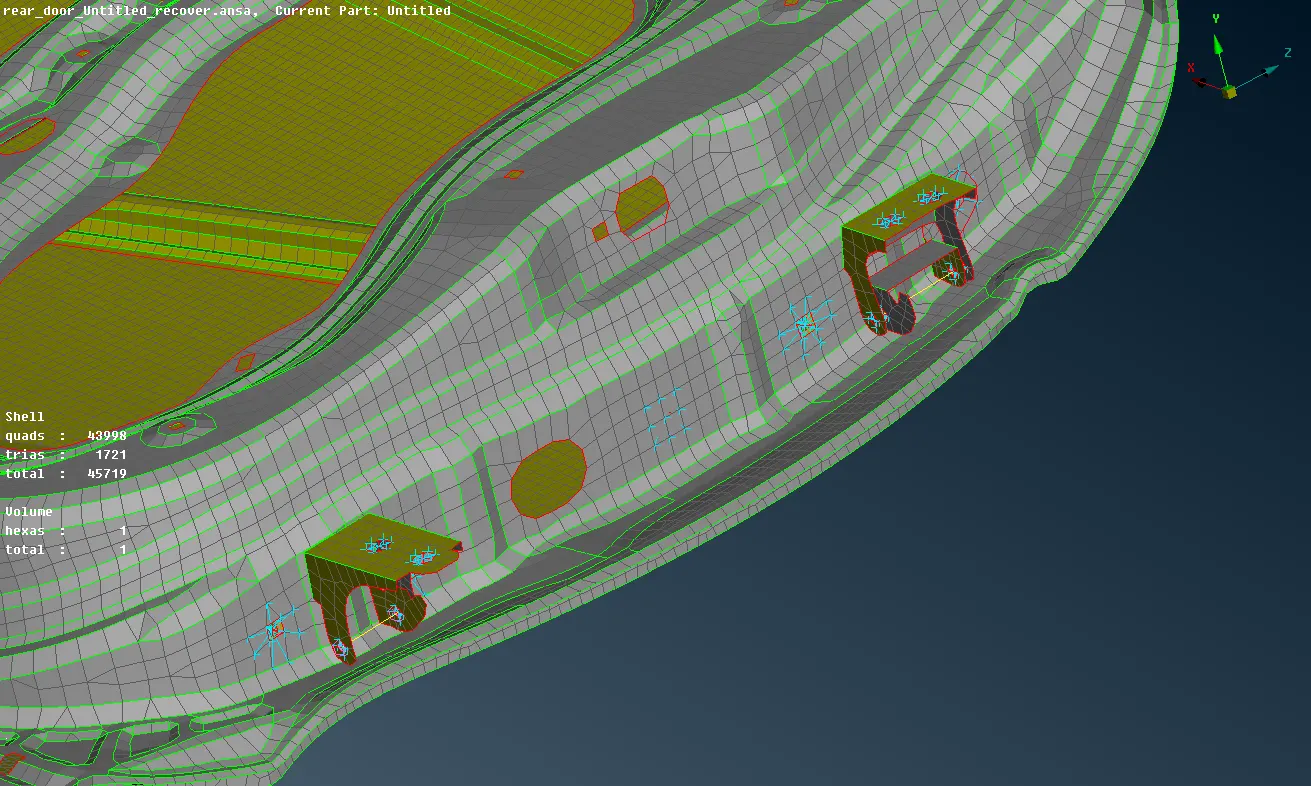
Weld Connection:
- Connecting a glass component to any system is very critical because of its brittle nature and also it can't be bolted or joined using adhesive.
- We need to extract the outer feature line of the glass from the FE model. Go to Mesh>Perimeters>Feat2Curve command and select the outer periphery of the glass model. Convert the generated curve to Spotlines.Spot lines are polylines where an array of spots can be defined. The array is constructed using two parameters, called “margin” and “spacing”.
- Select FE representation type as RBE3-CBUSH-RBE3. Define P1 and P2 for the connection and in search distance dialogue box put 10. Check the "Keep all branches" checkbox.
- Since the geometry is meshed, projections are generated as soon as the realize button is pressed.
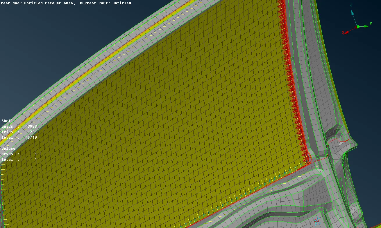
Spotweld: To create the spotweld in ansa for nastran domain, first we need to create a 3d point with the edges of the elements. Then convert those 3d points to Spotweld points by Convert>3d points>Spotweld points. Clicking the middle mouse button will take us to the connection manager. Set the two parts as P1 and P2. Select FE representation type as RBE3-HEXA-RBE3. Put 20 as search distance. In RBE3 pinflags dialogue box fill 123456 to restict all degree of freedom. Create a solid ID that will determine the material of the spotweld element. Click apply and Realize to create the spotweld.
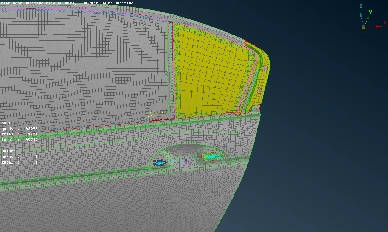
- The complete door handle will not be modeled in ansa and it will be represented as a mass element. Capture the rigids with many nodes RBE2 elements. Mass is assigned at the master node of the RBE2 element. Activate CONMi>CONM2>Nodes command and select the node where the mass has to be applied. In con mass tab we have to input the mass as tonnes. Convert the mass in tonnes as it is the standard input here.
CONCLUSION: -
- Achieved proper connections between different sub-systems of the rear door
LEARNING OUTCOME: -
- Understanding about different types of connection in ansa.