Week 6
Aim
To make the necessary connections in the rear door model using Nastran deck.
PROCEDURE
As the model was already mid-planed and meshed, only connections were performed.
On this model there are the following connections.
- Bolt RBE2 connection
- Simple RBE2
- Cbush-RBE3connection.
Bolt RBE2 connection
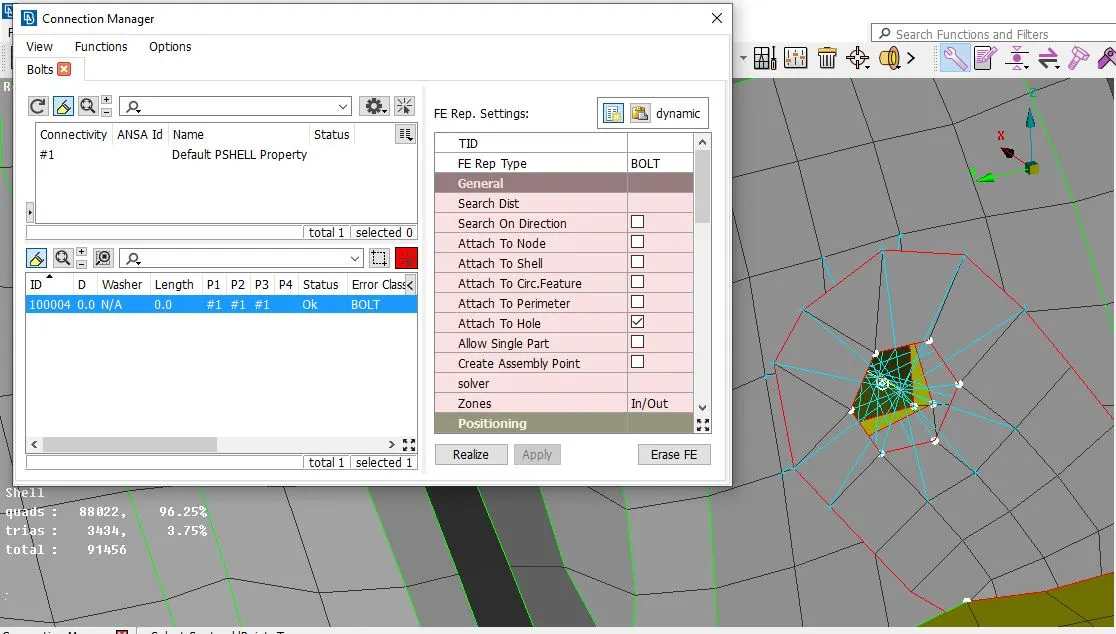
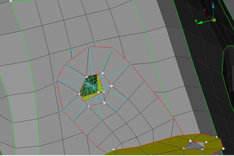
This connation was done in places where multiple parts were joined together by a single bolt. The bolt connection is realized as follows.
- A COG point were created using COG tab in topo deck. This creates a center point with respect to all the points selected.
- After creating this point, using conversion manager the point was selected and the 3d point was selected and converted to a bolt entity.
- To realize the connection, connection manager was selected and the bolt entity was selected.
- The window pops up and we give part-1 and part-2 after which the type of bolt was selected. Then the search distance was given as 50mm.
- Then we click realize and the connection is realized
Simple RBE-2 Connection.
A simple RBE2 connection was performed in places were two parts had a rigid connection in between them. It constrains all degrees of freedom if needed.
RBE2 connection are of two types. A many node RBE2 and two node RBE2. A many node RBE2 connection is simple. It makes connection between all the nodes selected and a single center master node. A two node RBE2 creates a nodal connection between two selected nodes. It usually used to create bolt connection with bodies.
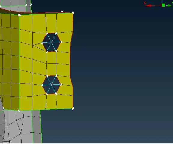
A many node RBE 2 were realized a follows:
- The RBE2 tab was selected from the Nastran deck.
- Then the nodes to be rigidized were needed to be selected. So the set of nodes were selected using nodal selection.
- Then the connection is realized as a cluster RBE2. That is all the selected nodes from the two parts were connected rigidly to center point.
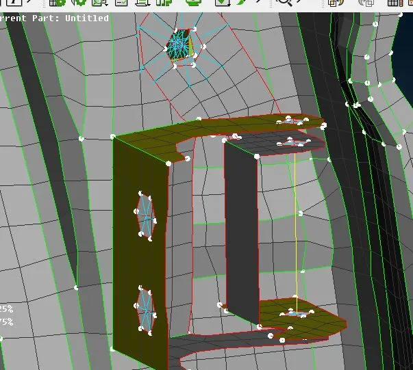
A two RBE2 connection was performed as follows.
- The RBE2 tab was selected from the Nastran deck.
- Then the nodes to be rigidized were needed to be selected. So the set of central nodes were selected using nodal selection.
- The connection was realized between two central nodes selected.
The two node RBE2 connection was made to connect a door hinge. Two simple RBE2 ‘s were made and their central nodes were connected and the direction of rotation was left free by removing that respective degree of freedom from the ones to be constrained.
Cbush-RBE3 connection
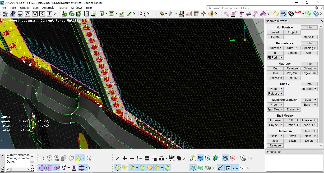
A Cbush-RBE3 is used to connect the sliding and fixed door glass to the door frame. A rigid connection can’t be used as the glass is not rigidly connected to the door panel. Also this connection can resemble the weather strips found on the glass door. It has damping constants typed in the property box in all direction.
It was performed as follows:
- A curve was created from FE model. Then the curve was converted using conversion manager into a spot line.
- The spot line was made into a connection using C-BUSH connection using connection manager.
- The part-1, part-2, spacing and type of connection were chosen. Then the search distance was given.
- The connection was realized.
- All the c-bush elements were aligned to the global co-ordinates by editing the properties.
All the sides of glass were separately connected in a similar fashion.
CONCLUSION
The model wass connected as needed using the above mentioned techniques. thus project gave how important it is to connect the diferent PID's as needed to give a correct simulation of actual case.
https://drive.google.com/file/d/1KYSr-9APt8Esq0t3VZfbrLWa_G4TtiD-/view?usp=sharing