Connection deployment over meshed Assemblies and Sub Assemblies using ANSA platform.
Aim:- Is to deploy connection over the various part of the Rear Door model and make it ready for NASTRAN deck-NVH Simulation.
Methodology:-
1) Import model and Go for Geometry check.
2)perform topo on it. As the model is too distorted after importing from different software. Topo helps to merge the adjacent surfaces and clear most of the errors in the process.
3) After visualizing the model, we get the idea about which category model will fall into. Like sheet metal/plastic/casting part. So, we can choose the meshing option accordingly.
4) For the sheet metal part which has a thickness of less than 6 mm or measurable thickness, we can go with the Shell Mesh option.
5) For casting / plastic part if the part having thickness more than 6 mm, solid meshing is preferred.
6)Check for geometrical errors and clean them.
7) After doing Geometry clean up, now we are ready to do meshing by preferring any of the above methods (Shell mesh / Solid mesh) as per the given model. (Here we are preferring solid mesh as the given model have a thickness of more than 6 mm in some areas but we are going with 3d mesh all over the model)
8) After Mesh deployment is complete the Next step is Connection Deployment over the different parts of the assembly as per the given connection data.
Procedure:-
1) The obtained File of the model was.NAS file which can't be open directly so the first thing is to call out that file by Input Nastran deck.
2) After I open the file I get to know that the file was saved in one single PID.
3)It is difficult to work on Connection if the entire model assembly is in a single PID, so I decided to save each part in different PIDs.
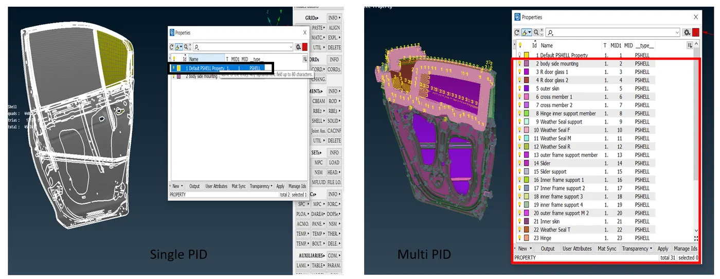
Image- 1
As you can see in the above image left side is when I open the model for the first time and the right one after assigning PIDs to each part.
4) As the model is pre meshed and FE was released it is easy and time-saving to work only on the connections.
5)The next thing I did after Saving PIDs is to identify the parts where I have to give rigid or bolt or weld connections.
Now we have come to the connections lets talk about it in brief,
Connections
Normally in-vehicle BIW there is a wide variety of connections are available to connect two-part with the same/different thickness to each other. Either by connecting them by Nut-bolt, Rivets, some time with welds (Seam weld & Spot weld) or we can go with Adhesives for some connections.
It's the Engineers' responsibility that assing appropriate connection throughout the body without compromising the strength, durability, operation of the two adjacent parts.
Apart from this, there is a wide variety of decks available for analysis like Nastran for NVH [Noise-Vibration-Harshness], ABAQUS for Durability, DYNA for safety, etc. Each of them holding their connection properties that we have to take care of.
For example
Let's take the same example of the door panel for which we did a connection in this project.
Now here we did connections that are more suitable to the NASTRAN deck for NVH analysis.
Each car door has a power window mechanism nowadays, which means your window can slide in the car frame as you push the button. SO when we passed this model for NVH testing we don't have to simulate the mechanism as we are gone testing it for NVH. Rigid/mass representation of a component like a handle and motor is sufficient. So instead of locking window glass in all degrees of freedom, we can choose the option of giving insulation/ vibration/ noise dampening connection as we are gone testing for NVH. This way we can found out better result over NVH testing.
On the other hand, if we are planning to do the Durability test which is possible with the ABAQUS deck then we have to change the plan of action here and there. As we know in this scenario we can test the durability of the actual mechanism inside the door. Here we have to focus on movement rather than just a solid representation of it. To test out the Durability of the window mechanism we have to focus on the degree of freedom over which the window is sliding, take account of motor movement, and need to deploy appropriate connection accordingly.
The conclusion is a type of connection depends on Deck and for which analysis we are deploying the connections.
6) After analyzing the model I get the idea about where and what type of connection I should be deploying over the model.
There are two ways with we can Deploy the connections, one is the Manual method and another one is the Automated one.
the benefit of Manual over Automated is The ANSA asked us where to store the connections and what name should be given to each connection which helps us to sort out connection on our will, But for more complicated model automated one comes in handy.
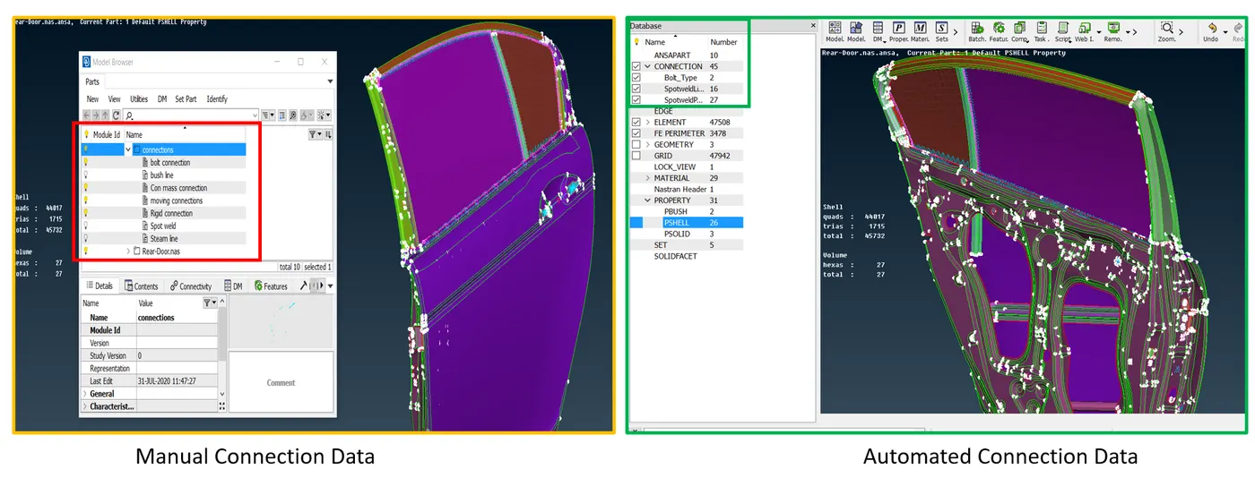
Image- 2
As you can see in the above image data of connection get stored in two different areas depending on which method you are using. As I said earlier with the manual method [Spider/cluster connection, rigid connection, ] ANSA asked us where to store the connections and what name should be given to each connection. You can save the data in "Model Browser" and get access to all stored connection data at any time. here as you can see I made a new file for every type of connection like For bolt connection where I stored all bolt connections in the model, Rigid connection which holds the data of all rigid connections inside the model likewise for every other connection.
I just made a new folder named '' Connections" to store the data.
The Data of connections that are made by the Automated method automatically get segregated to the Database to their respective folder as you can see in the right side image.
7) I had completed the model with a combination of both type of connections,
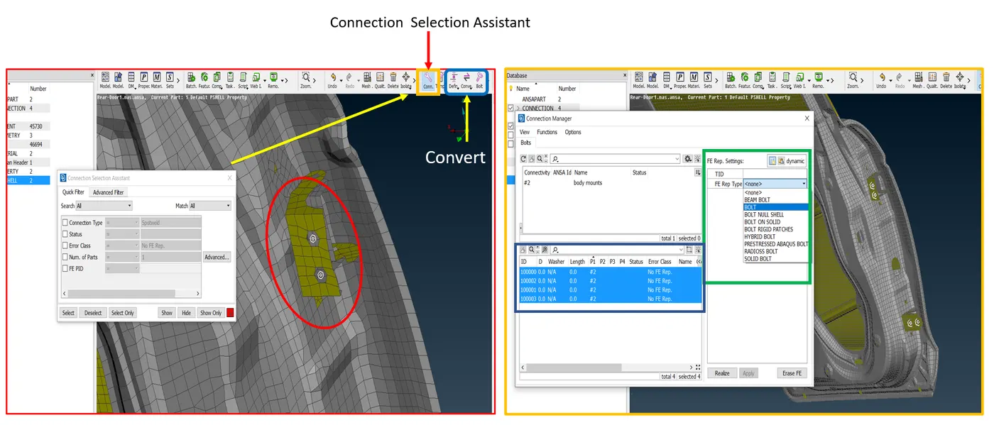
Image- 3
Here I deployed Bolt connection, The steps for it as follows.
First I had put 3d points where I see the hole which is a strong indicator of bolt/rivet / any sort of fastener connections (* Not all holes are for fasteners, some are made for weight reduction/extra mountings, etc. *), For that Topo deck --> Points-->On COG by using On COG option we can add 3D point on the surface, edge, circle, sphere, etc.
After creating 3D points I went through the Convert option (Left image corner) you get the options list as bellow,
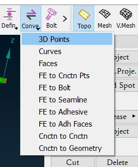
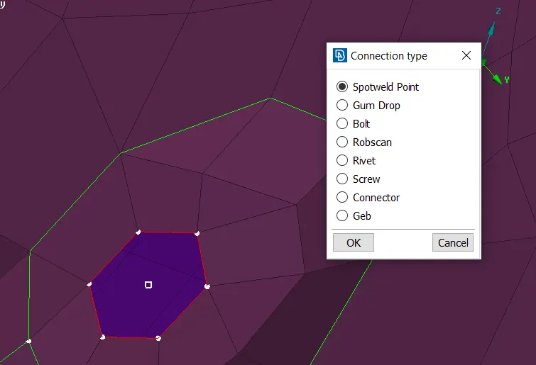
Image- 4
After clicking on convert ANSA asked us to select the 3D point with this, you get the options to convert 3D point into the bolt, spotweld, etc as you can see in the above image 4.
After converting 3D point into the bolt next step was going to "Connection selection Assistant", While the CSA window is activated, select the converted bold points (* Line in case of the curve for spot weld lin/ steam weld line*) and press mouse middle button to execute the command. Now you can see the "Connection Manager" window as shown in image 3 (R).
Here from this window, you can select what type of connection you want to deploy and for which parts. this method is handy when two parts have to be connected by bolt, rivet, seam weld, spot wed, etc. Ansa will give a wide verity of options to choose from.
Connection By Manual Method
As we discussed earlier we can deploy manual connection to represent these bolts also but the procedure is slightly different,
For this first, we have to move to the NASTRAN deck where you can see the numbers of Modules button for connection but here we have gone used "RBE2 Many nodes and 2 Node RBE2" connections to represent the fasteners.
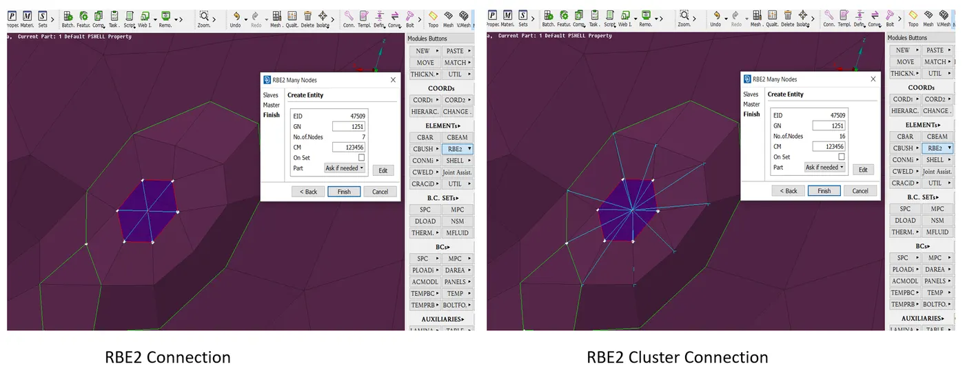
Image 5
The Left side image shows the normal connection while the right side shows the Cluster / Spider connection. Any method of representing bolt is ok but doing as cluster connection preferred as best practice. The reason is when the model goes through an analysis the elements near connection undergoes lots of pressure and stress. if we connected them like Left side image there are more chances of generation of stress concentration area near nodes but when we capture elements in zone-wise (washer) as shown in the right side image then applied load is evenly distributed through the elements and we get the better results.
8) After did the Fastener connections I had moved to Rigid mass / Concentrated mass connection where we have to represent the parts as a mass object that don't have any significance in the respective Analysis. Like here we are doing NVH so we don't need the Handle model it just consumes more time during the simulation. So I had represented the Handal as Con mass connection, we can do this to the motor also if its data is given.
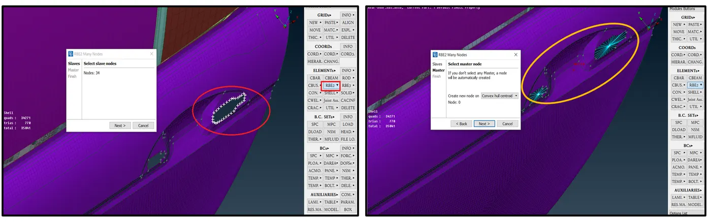
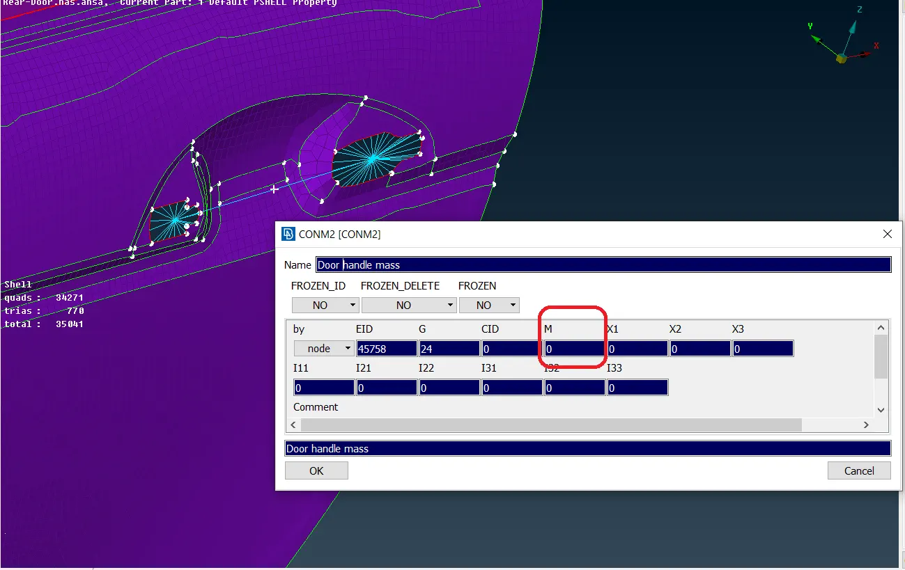
Image 6
Here I capture the feature with RBE2 many nodes Rigid Connection and then connected them. You can see the Master node is created middle of that two-door handle feature.
The Next Step was given that point a Concentrated mass to represent it as an actual handle for this their is a button in NASTRAN deck named CONMi which gives access to the window you are seeing in 3rd image The mass value should be in Tonnage. This mass data is usually given to us or mentioned in the respective datasheet.
9) The next is Spot weld Joints. I had deployed spot weld through various parts of this model. The procedure is fairly simple and the same as what did for bolt automated connection.
Here is one example for better understanding,
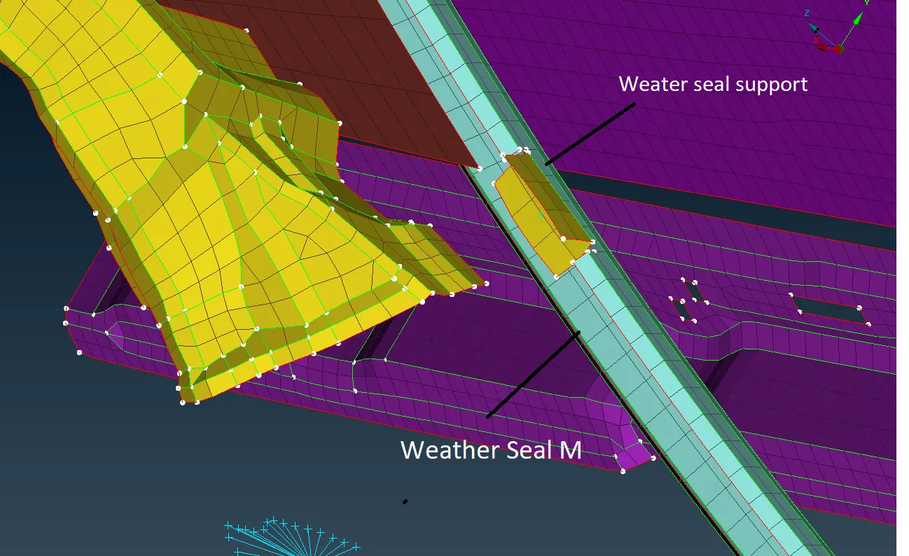
Image 7
As you can see in the above image there are two parts that I am gone connected with spot weld (* In spot weld ANSA created 3D element between two surfaces that you want to connect*)
As per the bolt connection procedure, I first made one 3d point on the surface of one part as you can see. then convert that 3D point into a spotweld point (ref. Image 4). After that went to the "Connection selection Assistant" select the converted point and press the middle mouse button to open the connection manager window. Note that the ANSA automatically detect the connection and show you option accordingly. As here we select the spot-weld point it will show you connection related to the spot weld. For the NVH NAstran deck we go for the "RBE3-HEX-RBE3" connection type which represents Spot weld.
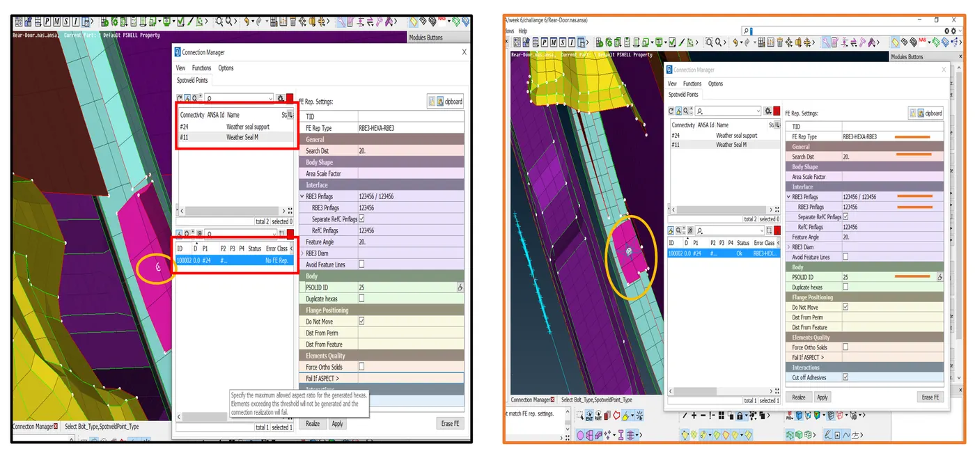
Image 8 Image 9
Let's see about Connection Manager
this window contains lots of data about which connection we want to deploy and on which parts, their properties, type, etc.
First, go through the Left part of the window which showcases PID and names of the part that we want to connect. (Same for any connection)
On the left bottom side of the connection manager window is a place where you can select the part you want to connect. You can see the title P1, P2, P3, P4, Status, Error, etc.
The P stand for a part. By right-clicking on p1 title bar and type press F1 unable us to make a selection of respective components directly from the model screen which is more handy and easy as compared to manually feed PID in that column.
The status bar shows that the connection execution is done properly or not as you can see in image 9 that I did get status OK after the execution of spot weld successfully.
Now let's talk about the right side of that same Connection manager window. As you can see in the image it will help to select the right type of connection, set different properties for those connections, and stored that Connection in a separate PID. There is an option for constraint Degree of freedom of connection, search distance option is there which helps ansa to find target part within input value.
In Image, you can see the deployed Spot weld connection.
10) Here is one error I got during deploying spot weld connection,
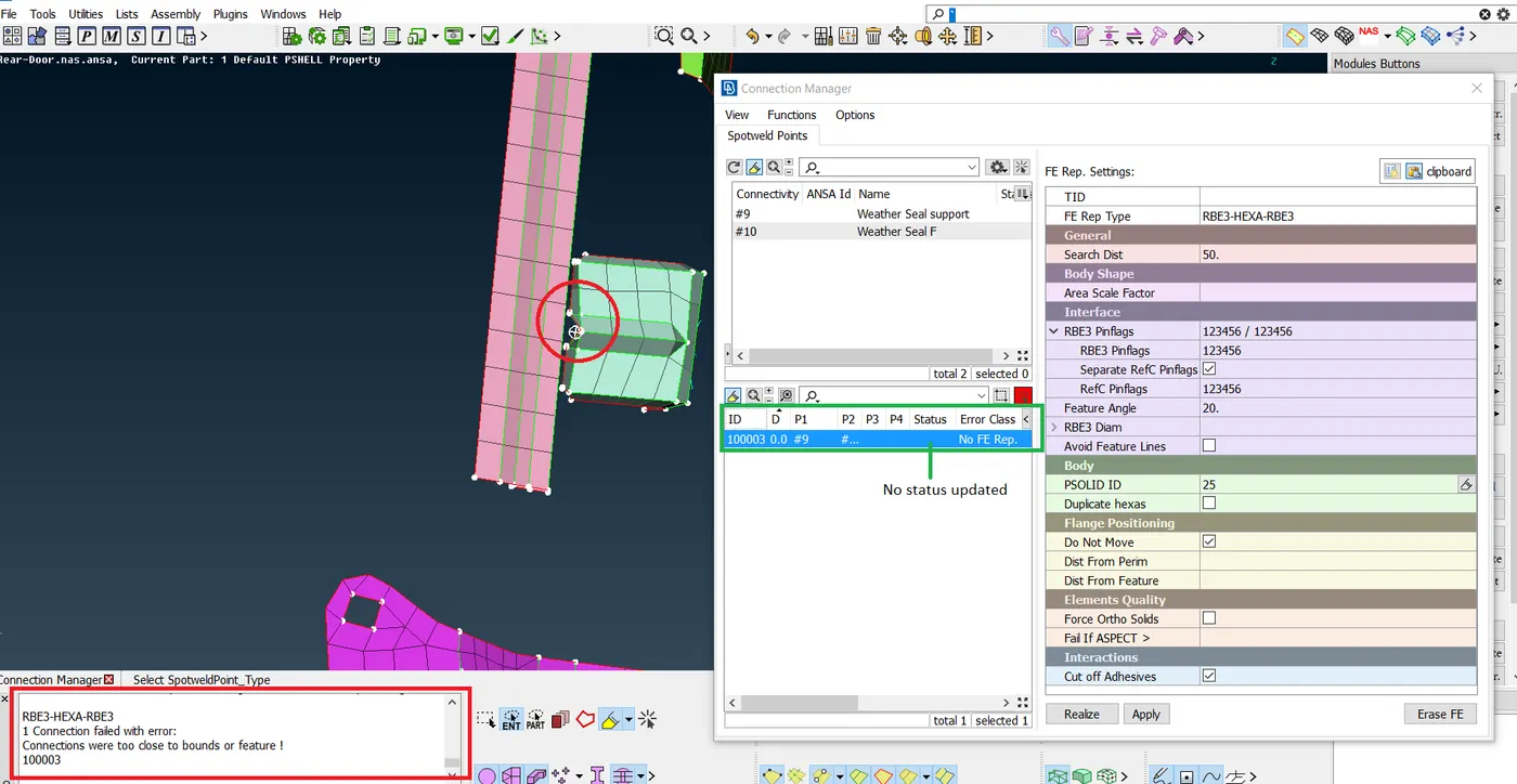
Image 10
Here at the bottom left corner of the info bar, you can see the error. This error restricts the connection over the part.you can check the status in the Connection manager.
What we can do in the situation like these?
Here is one solution, as we all know that these two parts and may other parts like these which fell for the same error have one thing in common that they are connected with Rigid connection (* Spot weld is one sort of rigid connection). And we all know that this is not the only way to deploy the rigid connection. We can Deploy RBE2 rigid connection in these sorts of cases that are valid and simulate the spot weld DOF constrain.
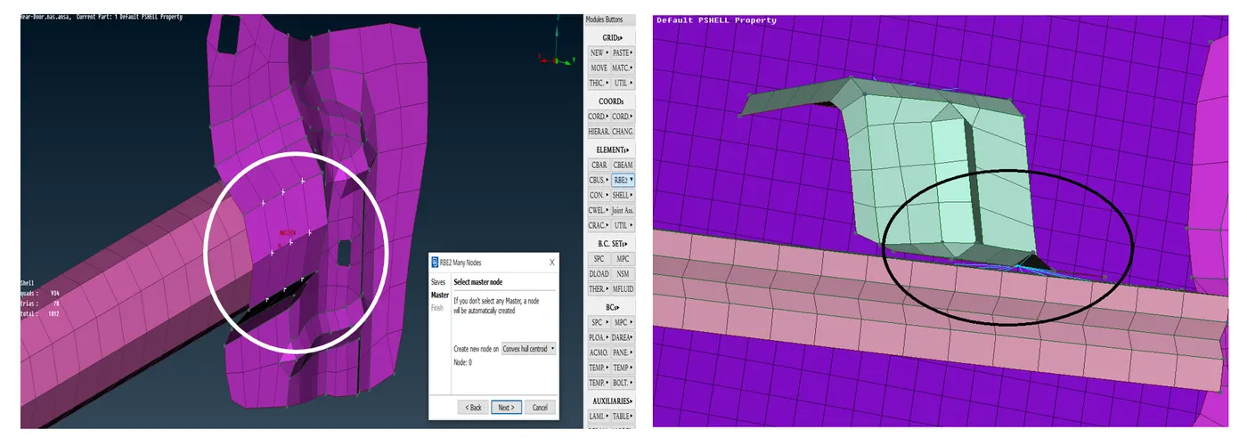
Image 11
This sort of rigid connection is acceptable where we find it difficult to deploy any other sort of connection.
11) After deploying all rigid connections its time to deploy connection at the window glass part as the window has glass material which was a slide in between sheet metal frame. Here first thing we have to understand is we are doing connections for NVH testing so the CBUSH connection is the best connection we can deploy between the window glass and weather seal. as it simulates the damping element through the periphery of the window which is the most suitable thing for NVH testing.
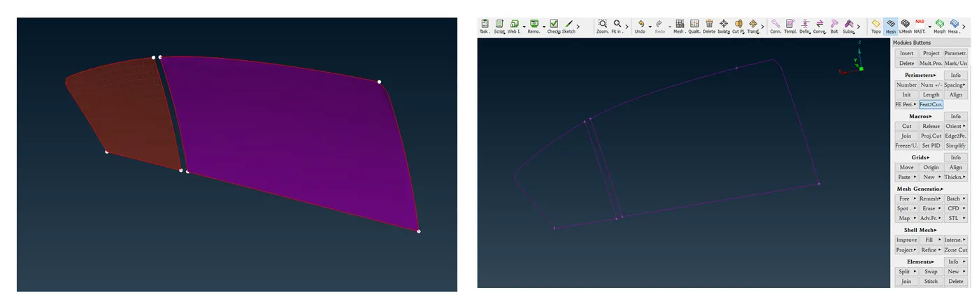
Image 12
So here is the procedure, First I capture the window glass borderline by Feat2Curve option which was in Mesh module. After extracting the outer surface curve I converted that curve lines into Spoyweld line using the Convert option. Now I get the spot weld line. After this follow the usual step of calling "Connection selection Assistant" and select the curve for which I want to make a CBUSH connection.
After that Connection manager window get pop open Their I used the connection which will represent the Dampner which is nothing but "RBE3-CBUSH-RBE3"
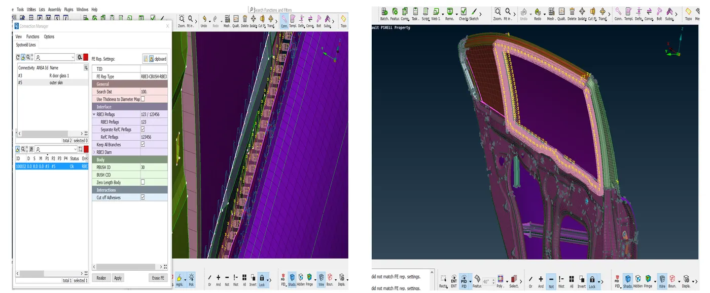
Image 13
The further procedure of deploying the CBUSH connection is the same as the Spot weld one. On the left side, you can see the closeup look of CBUSH after deploying. And on the right side was the result of complete CBUSH connection Through all corners.
12) At this step of connection, I deployed all possible connections to the model. Just one thing remains the Last CBUSH connection we made. These CBUSH connections will follow the vector orientation when deployed. Its the default setting in ANSA. These orientations also called local /Vector coordinates which are independent of the Global co-ordinate we followed up until now.
For the last step, we have to Change these vector co-ordinates into global one for this we have to go to the "database" tab where we can find the CBUSH connection IDs.
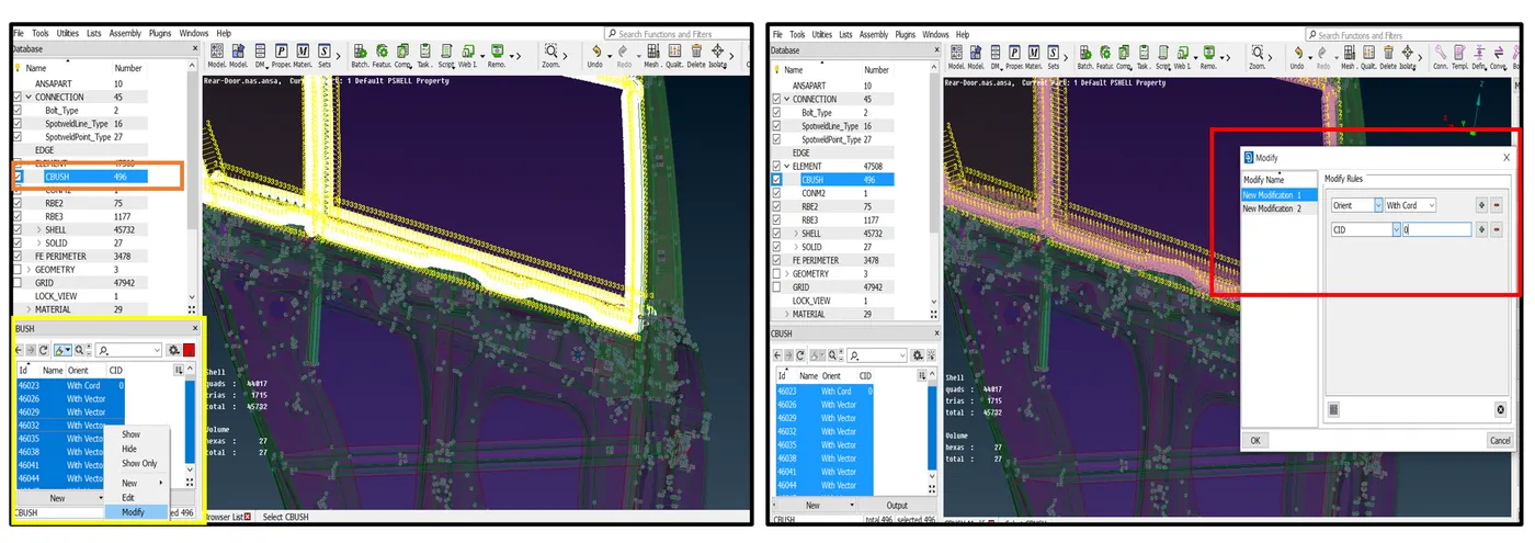
Image 14
As you can see in the left side image we have a total of 496 CBUSH connections, Now by at the bottom left you can see the IDs of each Cbush along with their orientation, and it's showing Vector Cord except for the first one that I changed manually. But we can't go and change their orientations like this there are a total of 496 of them so the best practice is to select all like I did and right-click to get access to the Modify option.
As soon as you click on that option a "Modify" window will pop-up as you can see on the right side there is an option for creating a modification file and what modifications you do in this window will apply to all selected connections in our case CBUSH connections. I select which property I want to change and to what which is orient and CID = 0 respectively in our case. After hitting enter we will get the result we want.
Other Projects On which I had did Connection Deployment
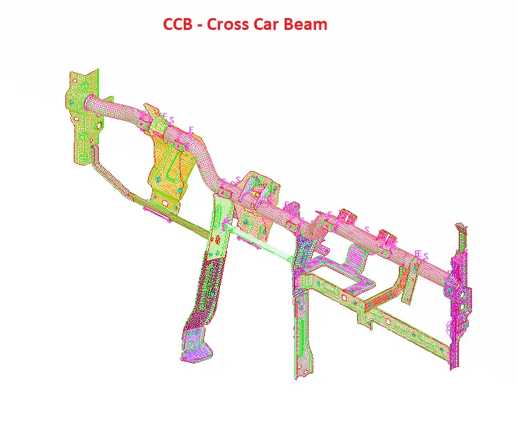
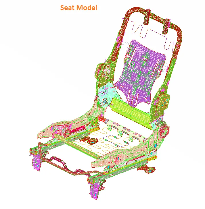
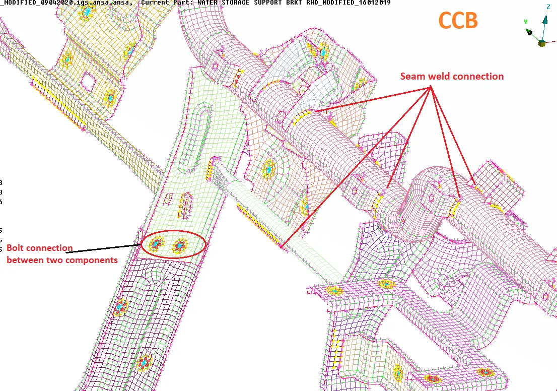
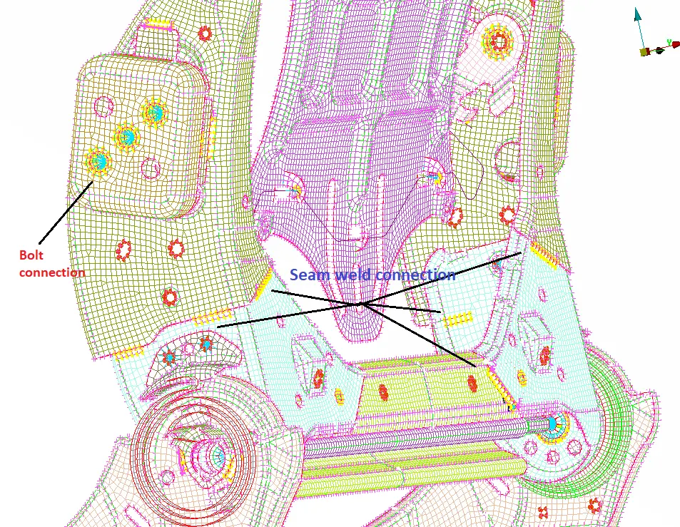
For these projects, I had extracted the MID surface from their geometry, Set them into New PIDs as per their thicknesses, and Deployed 2D element mesh on Them. After complete meshing, I had Deployed the appropriate connection on them. The Steps for the Connection Deployment are the same as we have discussed in the earlier segment of the report.
Here are some screenshots
Learning Outcomes:-
1) Learn about an important part of pre-processing which is nothing but the connections.
2) Learned different types of connection their significance for NASTRAN deck, their property, elemental representation.
3) Understand the right approach while doing connections. Learned how to deal with the situation where no sufficient connection data is provided.
Conclusion
1) If there is no sufficient data available over the particular connection, the designer should assume that and free to do connection on its own but 90% of the time a rightful data is given to the engineer for connection.
2) we can't do the cluster connection for a hole having only 4 nodes. It will apply only for the holes having more than 4 numbers of holes.
3) Not every hole is mean to be represented in rigid/bolt/rivet sort of connections some holes or cavities are given in the model for weight reduction or achieve some other important purpose.
4) Types and DOF of the connections are dependent on the Deck we are gone used and the type of simulation we are gone perform.
5)The parts which are not falling under the Deck/ simulation platform can be represented as CON mass to avoid complication and reduced the simulation time.
6) As per new model guidelines, the orientation of the connections should be the same as part/ global coordinate system.