Rear View Mirror Solid meshing in ANSA
AIM :
In the Rearview Mirror model check for the geometrical errors and mesh with volume tetra elements as per the given quality criteria and there should not kinks and dips on the surface of the component.
OBJECTIVE :
For the given component, check for the geometrical errors and mesh with the given element Quality criteria. Use tetra elements to model the component and there should not and kinks and dips on the surface of the component.
|
S.No |
Quality Criteria |
Value |
|
1 |
Target/Average length |
1 |
|
2 |
Minimum Length |
0.5 |
|
3 |
Maximum Length |
2 |
|
4 |
Tetcolapse |
0.2 |
PROCEDURE :
Model Importing & Geometry Clean up :
1. Import the given model by using File-->Open option and import Rearview mirror.IGS file.
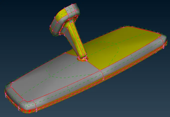
Fig: Rearview Mirror
2. Go to Topo-->Faces-->Topo option and select all CONS and Click ok to stitch all CONS with each other.
3. Go to Tool-->Checks-->Geometry for Geometry Clean up.
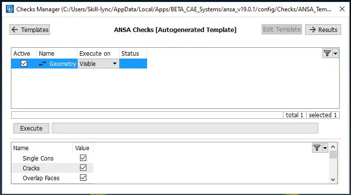
Fig: Checks Manager Window
4. In the above Checks Manager window click Execute to check any error occurred in the Model and fix the Error and Cleanup the Geometry.
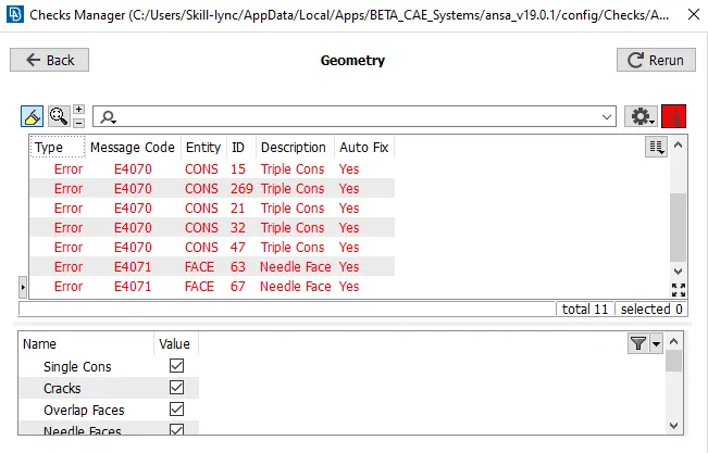
Fig: Error in Rearview Mirror Model
5. In The above window, an error has occurred in the given Geometry model. Check the error showing in the Model and fix the issue and clean up the Geometry.
6. While resolving the error, Right Click on the error which is going to resolve and click Show only option.
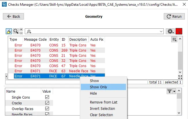
Fig: Eliminating the geometrical error
7. It will show only that Needle Face. Using Face-->Delete Option to delete the Unwanted Needle Face.
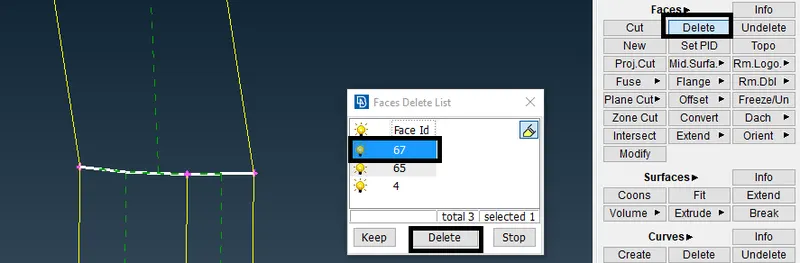
Fig: Deleting Needle Face
8. After deleting the Needle Face, that error has been resolved. Similarly, all errors have to be fixed, and again Click Execute in the Checks Manager, and 100% Geometry Cleanup is to be verified.
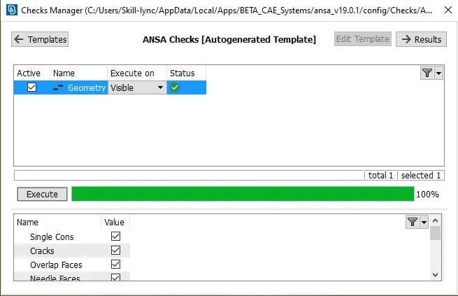
Fig: Eliminated Geometrical errors
Meshing :
9. Set the given Quality Criteria for the Component.
10. Go Utilities-->Quality Criteria-->Shells Option and assign the given Quality Criteria Values.
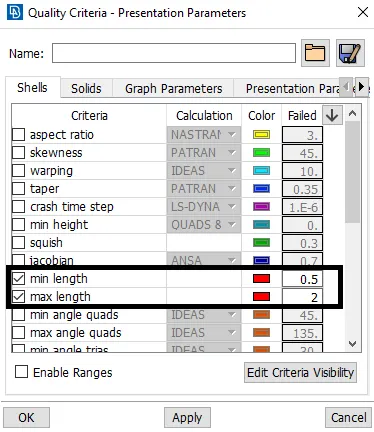
Fig: Quality Criteria
11. After assigning the Quality Criteria for the Component, Go to Utilities-->Mesh Parameters and Set Orthotria and assign the Target Length Value for TetraMeshing.
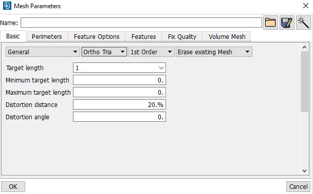
Fig: Mesh Parameters
12. Go to Mesh-->Perimeters--> Length Option and Select the Component to Mesh and enter the Value of Perimeter Length and Macro Length for Meshing.
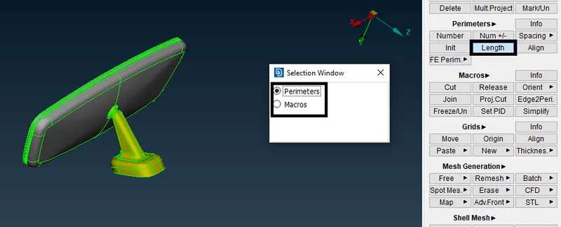
Fig: Parametric Length
13. Go to Mesh-->Mesh Generation Option and Select the Mesh type to mesh the component.
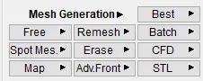
Fig: Mesh Generation Types
14. Select Spot Mesh with element type as ortho tria and select the fillet area and do tetra mesh.
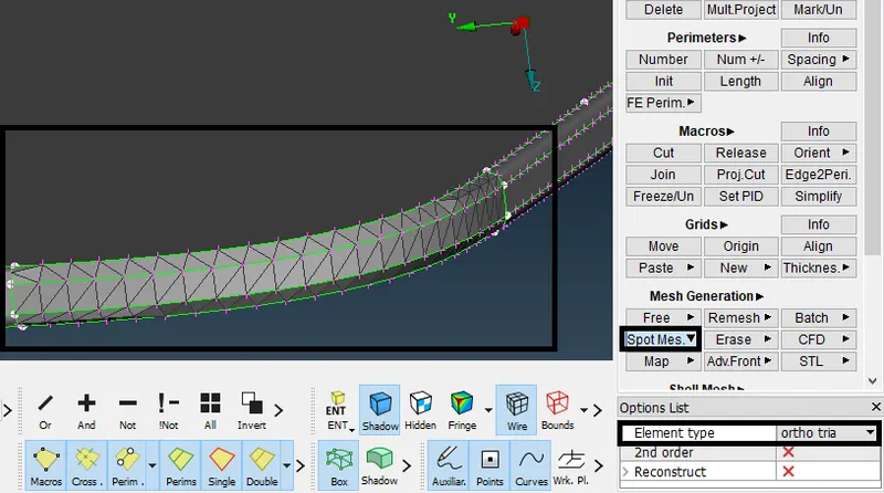
Fig: Tetramesh using ortho tria in fillet region
15. Select Spot Mesh with element type as tria and select the normal Surface and do tetra mesh.
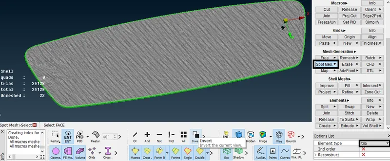
Fig: Tetramesh using ortho tria in normal surface
16. After Meshing for all surfaces, Check if there are any off elements is present and eliminate the off elements.
17. Go to Mesh-->Grids-->MV Free option and select the nodes and move in x,y,z, direction to clear the quality issue.
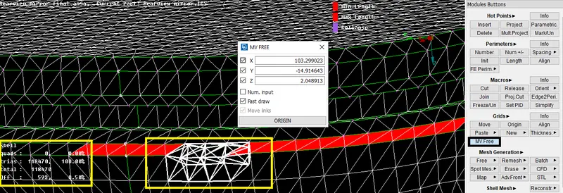
Fig: Eliminating off elements (Min & Max length)
18. Similarly eliminated all other off elements (Min & Max length) by using MV Free option.
Volume Tetra meshing :
19. Set the given Quality Criteria for the Component.
20. Go Utilities-->Quality Criteria-->Solids Option and assign the given Quality Criteria Values.
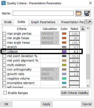
Fig: Quality Criteria
21. After assigning the Quality criteria, Go to Volume Mesh-->Volumes--Define-->Manual option and Define the Volume.
22. Go to Volumes-->list option and check the defined volume.
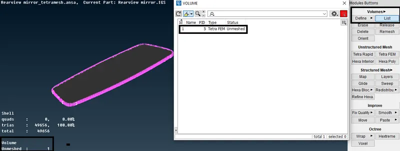
Fig: Defining a Volume
23. Go to Unstructured Mesh-->Tetra Rapid (or) Tetra FEM option and select the Volume and start meshing.
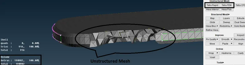
Fig: Unstructured Mesh using Tetra FEM
24. After Meshing, switch off the geometry & FE-mode option and display only the Volume option to verify the volume mesh.
25. Switch on the Bounds option to control the visibility of solid bounds.
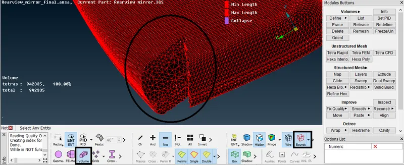
Fig: Volume Tetra elements
26. Similarly done for all surfaces and Check if there are any off elements(collapse) is present and eliminate the off elements.
27. Go to Mesh-->Grids-->MV Free option and select the nodes and move in x,y,z, direction to clear the quality issue.
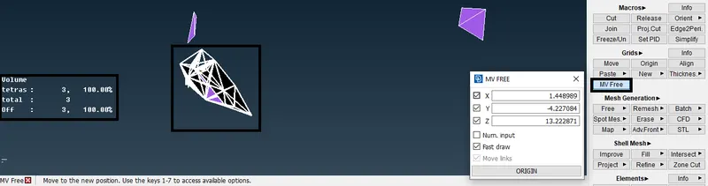
Fig: Eliminating off elements(collapse)
28. Similarly eliminated all other off elements (Min & Max length) by using MV Free option.
Learning Outcomes :
- Learned to Mesh the fillet area using element type as ortho tria and for normal surface mesh using element type as tria.
- Learned to mesh the Volume using Unstructured mesh (Tetra Rapid & Tetra FEM).
- Learned to eliminate the off elements (Min length, Max length & collapse) by using MV Free option.
RESULT :
For the given Rearview Mirror model, checked for the geometrical errors and meshed with element type as ortho tria & tria as per given quality criteria. After meshing defined the volume and meshed the volume by using unstructured mesh (Tetra Rapid & Tetra FEM type). After mesh eliminated the off elements (Min length, Max length & collapse).
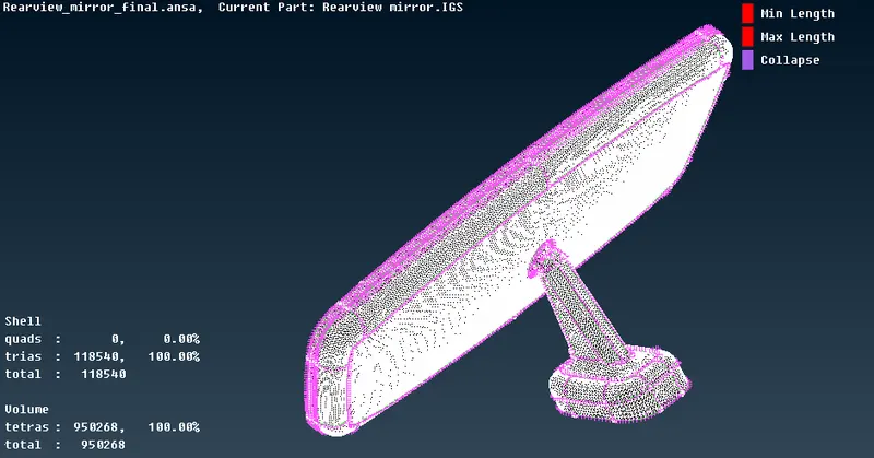
Fig: Rearview Mirror using Tetra Mesh