SOLID MESHING ON CAR REARVIEV MIRROR
Solid Meshing on Car Rearview Mirror
Aim-
- To perform 3D meshing on the Car Rearview mirror using ANSA as preprocessor software.
Objective-
- To check geometrical error in CAD model of Car Rearview mirror.
- To provide mesh parameters for 2D mesh on the surface.
- Deploy 2d mesh on the surface of the CAD according to quality criteria.
- Now we will create 3D mesh [Tetra mesh] on the CAD component.
- Now we will check quality for 3D elements mainly tet collapse.
Theory-
1. Car Rearview Mirror
- A rearview mirror is a flat mirror in automobiles and other vehicles, designed to allow the driver to see rearward through the vehicle's rear window (rear windshield).
- In cars, the rear-view mirror is usually affixed to the top of the windshield on a double-swivel mount allowing it to be adjusted to suit the height and viewing angle of any driver and to swing harmlessly out of the way if impacted by a vehicle occupant in a collision.
- The rear-view mirror is augmented by one or more side-view mirrors, which serve as the only rear-vision mirrors on trucks, motorcycles, and bicycles
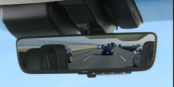
- Recently, rearview video cameras have been built into many new model cars, this was partially in response to the rear-view mirrors' inability
- To show the road directly behind the car, due to the rear deck or trunk obscuring as much as 3–5 meters (10–15 feet) of the road behind the car.
2. 3D-Meshing
It is also known by the term solid meshing or volume meshing. In solid meshing all three dimensions are comparable. (x~y~z). The element types are solid. The solid elements have 3 translational DOF The elements shape in 3D meshing are 1) Tetra 2) Penta 3) Hexa 4) pyramid.
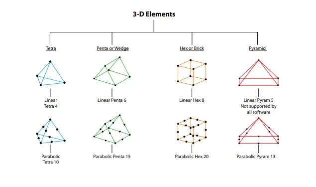
Volume Meshing
This is a method of representing a solid with the help of a 3D element inside the geometry. In this technique, we mainly use the tetra and Hexa element to define the geometry volume. The propagation of the element can be either structured or unstructured depending upon the requirement of analysis. They are mainly used for the auto-generation of the element in an unstructured method of meshing.
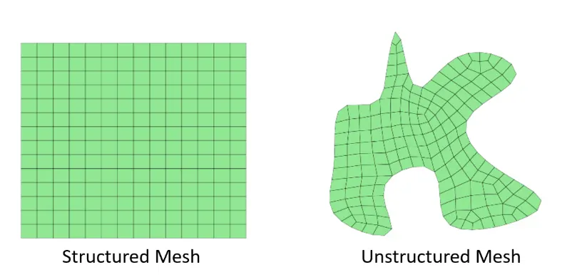
Structured Meshing
These types of mesh have implicit connectivity whose structure allows for easy identification of elements and nodes. Often these structured meshes have orthogonal quadrilateral(2D) or hexahedral elements(3D). it also possible to access coordinate easily because the size of the element does not vary from element to element.
pros
- Memory efficient
- Fast to solve
cons
- Hard to mesh for angle and curved surfaces.
Unstructured Meshing
These meshes have very general connectivity, whose structure is arbitrary and therefore the connectivity of the element must be defined and stored. The element types are non-orthogonal, such as trial element(2D) and tetra element(3D).
pros
- Complex-geometry easy to mesh
cons
- Slower to solve
- Greater memory requirement
Procedure-
Step 1-
Importing the model:
- Here we will be importing the CAD file into ANSA.
we will go on pull-down tab >> File >> open >> select the all format >> select the model from folder
Imported Model:
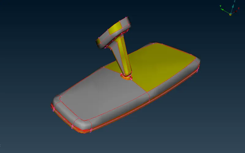
- This is the imported Rearview mirror CAD model.
- Since we use to import the CAD models in different formats so due to the software algorithm some geometrical changes are found after importing.
Step 2 -
Manual Geometric Check and cleanup:
- Go to topo module > Faces > Topo > Box selection for the model.
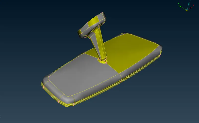
So after performing topo we should also check that is there any other errors present in the model or not such as,
- Unconnected surfaces.
- Unnecessary cons and surfaces.
- Damaged surfaces.
- Triple cons.
- Free edges.
so for that geometry check will Go to Toolbar > Check > Geometry
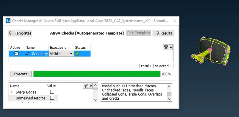
Step 3 -
Meshing:
Meshing for Rearview Mirror component-
Before meshing we will set all the quality criteria and mesh parameters. For this particular component, we will set only the maximum and minimum length for the 2D mesh.
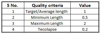
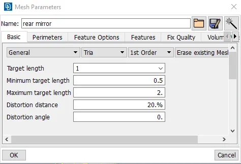
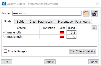
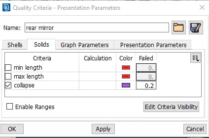
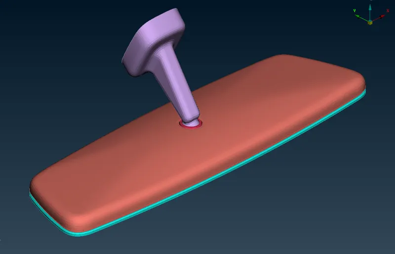
There are four components in this model:
- Spherical Bearing
- Mirror Frame
- Mirror
- Handle
We will start meshing one by one component,
Spherical bearing:
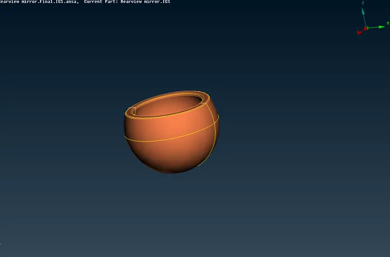
For meshing this component we will go to,
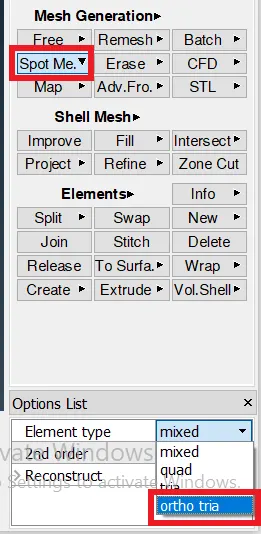
Mesh module > Mesh generation > Spot mesh (ortho mesh) > select component
As we can see here maximum surface portion of this spherical bearing is curved so for the curved surface we will provide ortho trias.
And on the flat region, we will use normal trias, which we can switch from here,
Start 2D meshing-
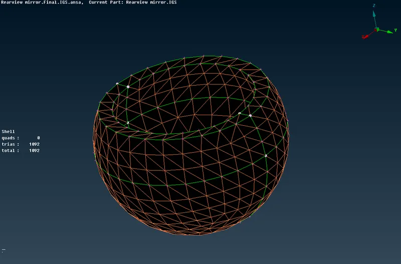
- Now after 2D mesh on the surface we will convert it into volume mesh.
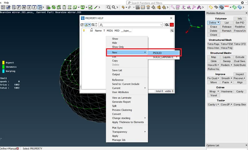
- Go to volume mesh module > Define > Manual > Window selection > Creat new PSolid
Creating new PID for PSolid:
Now when we will go to check the Volume list-
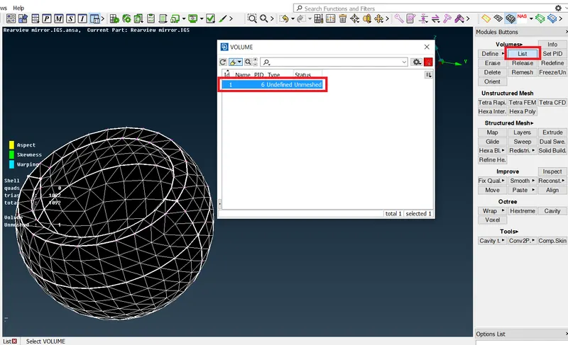
We can see one volume is created, and it has shown also that this is unmeshed,
Right Click > Remesh > Tetra FEM
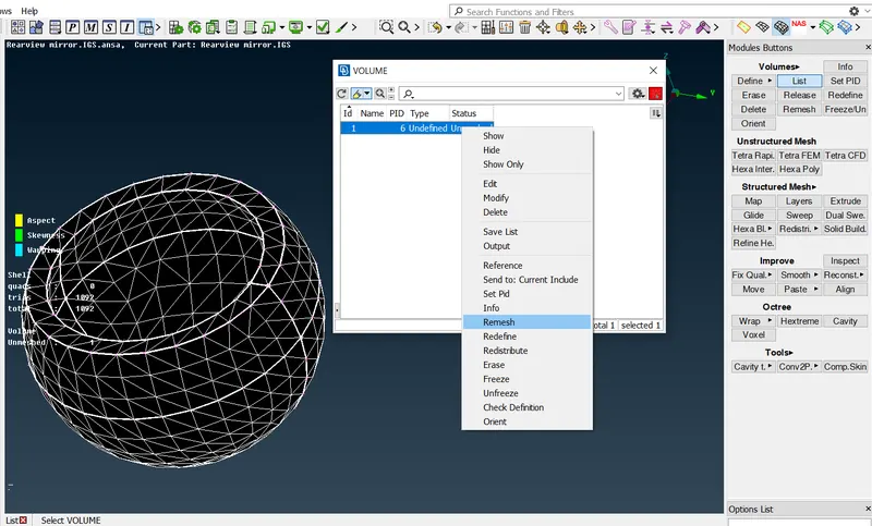
Now it is showing that this volume has meshed now.
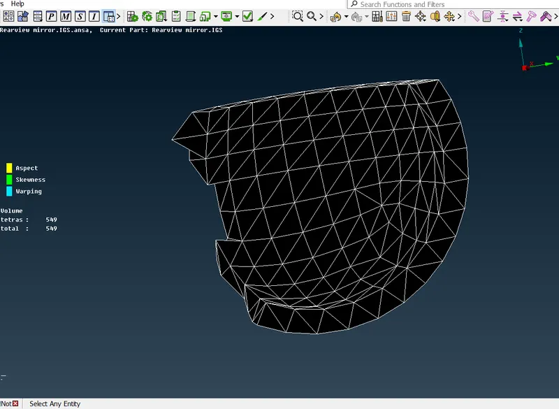
Similarly, we will do for other components also.
Mirror Frame-
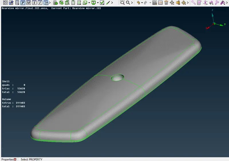
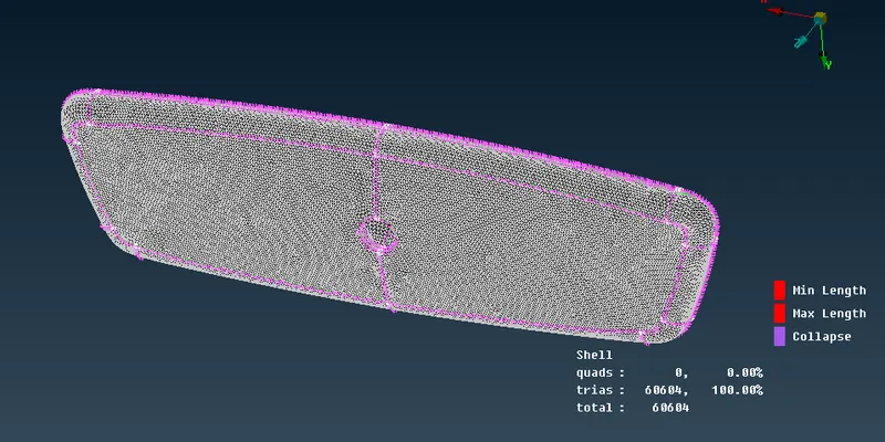
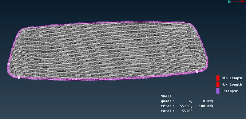
Mirror-
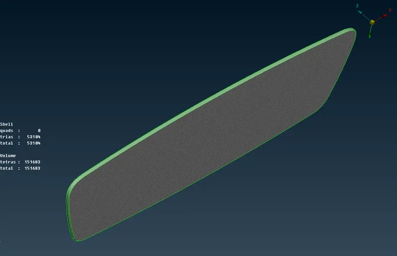
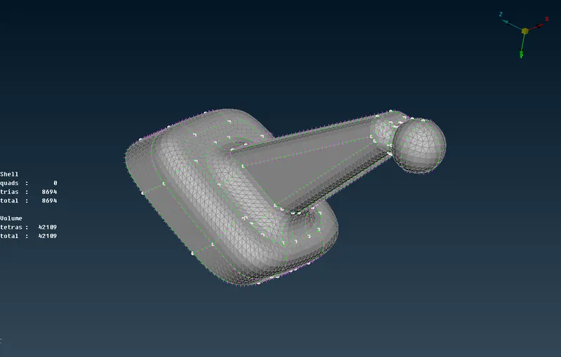
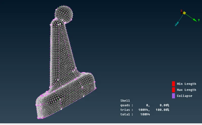
Mirror Handle-
Final Model-
Result-
- Here we have completed 2D shell mesh conversion to 3D volume mesh.
- With all the quality criteria fulfilled for 2D and 3D elements.
- All the geometrical glitches are eliminated successfully.
- All the feature has been captured successfully and provided better mesh flow.
- Very good connectivity was achieved between the surfaces.
- Archived zero element failure for this component.
Conclusion-
The volume meshed achieved is better satisfying all quality aspects and the surface achieved is also smooth without much kinks and dips. the usage of tho tria elements on curved elements has really made a difference in mesh smoothness, especially over fillet areas.
Learning outcome-
- 3D meshing on a solid object
- Fixing quality in 3D meshing
- Different algorithms awareness in volume generation
- usage of ortho tria elements on curved surfaces